1994 JEEP CHEROKEE heater
[x] Cancel search: heaterPage 989 of 1784
²Intake manifold air temperature sensor input is
monitored
²Throttle position sensor (TPS) is monitored
²The auto shut down (ASD) relay is energized by
the PCM for approximately three seconds.
²The fuel pump is energized through the fuel pump
relay by the PCM. The fuel pump will operate for ap-
proximately one second unless the engine is operat-
ing or the starter motor is engaged
²The O2S sensor heater element is energized
through the fuel pump relay. The O2S sensor input
is not used by the PCM to calibrate air-fuel ratio
during this mode of operation.
²The up-shift indicator light is illuminated (manual
transmission only).
ENGINE START-UP MODE
This is an Open Loop mode. The following actions
occur when the starter motor is engaged.
The powertrain control module (PCM) receives in-
puts from:
²Battery voltage
²Engine coolant temperature sensor
²Crankshaft position sensor
²Intake manifold air temperature sensor
²Manifold absolute pressure (MAP) sensor
²Throttle position sensor (TPS)
²Starter motor relay
²Camshaft position sensor signal
The PCM monitors the crankshaft position sensor.
If the PCM does not receive a crankshaft position
sensor signal within 3 seconds of cranking the en-
gine, it will shut down the fuel injection system.
The fuel pump is activated by the PCM through
the fuel pump relay.
Voltage is applied to the fuel injectors with the
PCM. The PCM will then control the injection se-
quence and injector pulse width by turning the
ground circuit to each individual injector on and off.
The PCM determines the proper ignition timing ac-
cording to input received from the crankshaft posi-
tion sensor.
ENGINE WARM-UP MODE
This is an Open Loop mode. During engine warm-
up, the powertrain control module (PCM) receives in-
puts from:
²Battery voltage
²Crankshaft position sensor
²Engine coolant temperature sensor
²Intake manifold air temperature sensor
²Manifold absolute pressure (MAP) sensor
²Throttle position sensor (TPS)
²Camshaft position sensor signal (in the distributor)
²Park/Neutral Switch (Gear indicator signalÐauto.
trans. only)
²Air conditioning select signal (if equipped)
²Air conditioning request signal (if equipped)Based on these inputs the following occurs:
²Voltage is applied to the fuel injectors with the
powertrain control module (PCM). The PCM will
then control the injection sequence and injector pulse
width by turning the ground circuit to each individ-
ual injector on and off.
²The PCM adjusts engine idle speed through the
idle air control (IAC) motor and adjusts ignition tim-
ing.
²The PCM operates the A/C compressor clutch
through the clutch relay. This is done if A/C has
been selected by the vehicle operator and requested
by the A/C thermostat.
²If the vehicle has a manual transmission, the up-
shift light is operated by the PCM.
²When engine has reached operating temperature,
the PCM will begin monitoring O2S sensor input.
The system will then leave the warm-up mode and
go into closed loop operation.
IDLE MODE
When the engine is at operating temperature, this
is a Closed Loop mode. At idle speed, the powertrain
control module (PCM) receives inputs from:
²Air conditioning select signal (if equipped)
²Air conditioning request signal (if equipped)
²Battery voltage
²Crankshaft position sensor
²Engine coolant temperature sensor
²Intake manifold air temperature sensor
²Manifold absolute pressure (MAP) sensor
²Throttle position sensor (TPS)
²Camshaft position sensor signal (in the distributor)
²Battery voltage
²Park/Neutral Switch (gear indicator signalÐauto.
trans. only)
²Oxygen sensor
Based on these inputs, the following occurs:
²Voltage is applied to the fuel injectors with the
powertrain control module (PCM). The PCM will
then control injection sequence and injector pulse
width by turning the ground circuit to each individ-
ual injector on and off.
²The PCM monitors the O2S sensor input and ad-
justs air-fuel ratio by varying injector pulse width. It
also adjusts engine idle speed through the idle air
control (IAC) motor.
²The PCM adjusts ignition timing by increasing
and decreasing spark advance.
²The PCM operates the A/C compressor clutch
through the clutch relay. This happens if A/C has
been selected by the vehicle operator and requested
by the A/C thermostat.
The optional Extended Idle Switch is used to raise
the engine idle speed to approximately 1000 rpm.
This is when the shifter is in either the Park or Neu-
tral position. A rocker-type 2-wire switch (extended
idle switch) is mounted to the instrument panel. This
14 - 28 FUEL SYSTEMJ
Page 1548 of 1784
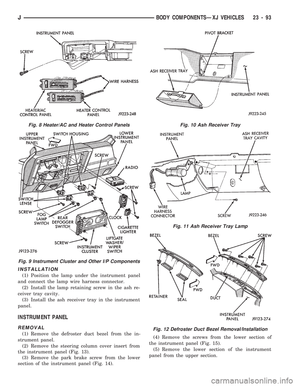
INSTALLATION
(1) Position the lamp under the instrument panel
and connect the lamp wire harness connector.
(2) Install the lamp retaining screw in the ash re-
ceiver tray cavity.
(3) Install the ash receiver tray in the instrument
panel.
INSTRUMENT PANEL
REMOVAL
(1) Remove the defroster duct bezel from the in-
strument panel.
(2) Remove the steering column cover insert from
the instrument panel (Fig. 13).
(3) Remove the park brake screw from the lower
section of the instrument panel (Fig. 14).(4) Remove the screws from the lower section of
the instrument panel (Fig. 15).
(5) Remove the lower section of the instrument
panel from the upper section.
Fig. 8 Heater/AC and Heater Control Panels
Fig. 9 Instrument Cluster and Other I/P Components
Fig. 10 Ash Receiver Tray
Fig. 11 Ash Receiver Tray Lamp
Fig. 12 Defroster Duct Bezel Removal/Installation
JBODY COMPONENTSÐXJ VEHICLES 23 - 93
Page 1551 of 1784
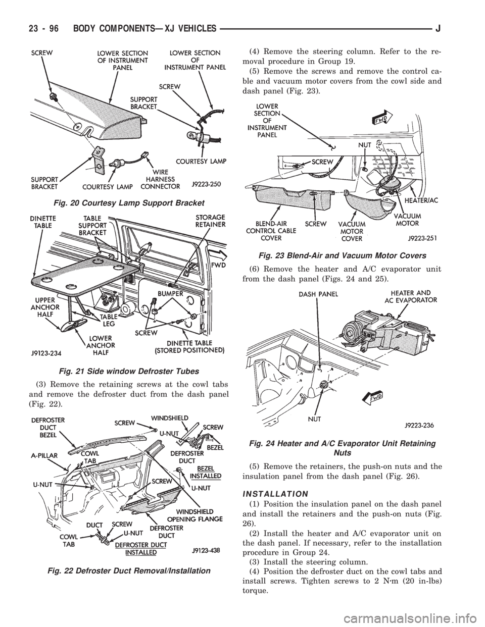
(3) Remove the retaining screws at the cowl tabs
and remove the defroster duct from the dash panel
(Fig. 22).(4) Remove the steering column. Refer to the re-
moval procedure in Group 19.
(5) Remove the screws and remove the control ca-
ble and vacuum motor covers from the cowl side and
dash panel (Fig. 23).
(6) Remove the heater and A/C evaporator unit
from the dash panel (Figs. 24 and 25).
(5) Remove the retainers, the push-on nuts and the
insulation panel from the dash panel (Fig. 26).
INSTALLATION
(1) Position the insulation panel on the dash panel
and install the retainers and the push-on nuts (Fig.
26).
(2) Install the heater and A/C evaporator unit on
the dash panel. If necessary, refer to the installation
procedure in Group 24.
(3) Install the steering column.
(4) Position the defroster duct on the cowl tabs and
install screws. Tighten screws to 2 Nzm (20 in-lbs)
torque.
Fig. 20 Courtesy Lamp Support Bracket
Fig. 21 Side window Defroster Tubes
Fig. 22 Defroster Duct Removal/Installation
Fig. 23 Blend-Air and Vacuum Motor Covers
Fig. 24 Heater and A/C Evaporator Unit Retaining
Nuts
23 - 96 BODY COMPONENTSÐXJ VEHICLESJ
Page 1552 of 1784
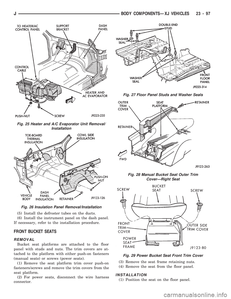
(5) Install the defroster tubes on the ducts.
(6) Install the instrument panel on the dash panel.
If necessary, refer to the installation procedure.
FRONT BUCKET SEATS
REMOVAL
Bucket seat platforms are attached to the floor
panel with studs and nuts. The trim covers are at-
tached to the platform with either push-on fasteners
(manual seats) or screws (power seats).
(1) Remove the seat platform trim cover push-on
fasteners/screws and remove the trim covers from the
seat platform.
(2) For power seats, disconnect the wire harness
connector.(3) Remove the seat frame retaining nuts.
(4) Remove the seat from the floor panel.
INSTALLATION
(1) Position the seat on the floor panel.
Fig. 25 Heater and A/C Evaporator Unit Removal/
Installation
Fig. 26 Insulation Panel Removal/Installation
Fig. 27 Floor Panel Studs and Washer Seals
Fig. 28 Manual Bucket Seat Outer Trim
CoverÐRight Seat
Fig. 29 Power Bucket Seat Front Trim Cover
JBODY COMPONENTSÐXJ VEHICLES 23 - 97
Page 1580 of 1784
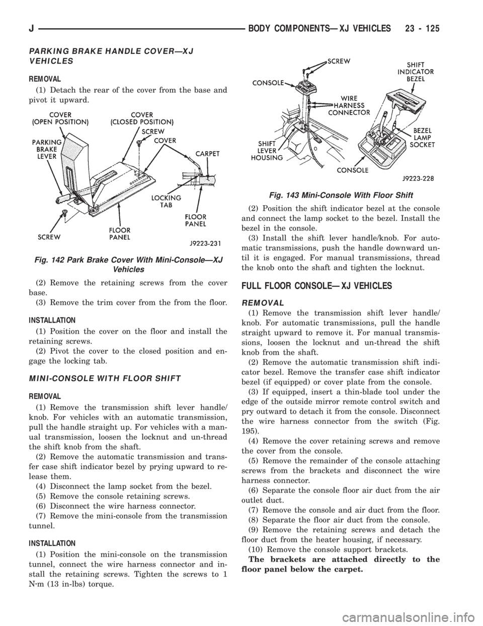
PARKING BRAKE HANDLE COVERÐXJ
VEHICLES
REMOVAL
(1) Detach the rear of the cover from the base and
pivot it upward.
(2) Remove the retaining screws from the cover
base.
(3) Remove the trim cover from the from the floor.
INSTALLATION
(1) Position the cover on the floor and install the
retaining screws.
(2) Pivot the cover to the closed position and en-
gage the locking tab.
MINI-CONSOLE WITH FLOOR SHIFT
REMOVAL
(1) Remove the transmission shift lever handle/
knob. For vehicles with an automatic transmission,
pull the handle straight up. For vehicles with a man-
ual transmission, loosen the locknut and un-thread
the shift knob from the shaft.
(2) Remove the automatic transmission and trans-
fer case shift indicator bezel by prying upward to re-
lease them.
(4) Disconnect the lamp socket from the bezel.
(5) Remove the console retaining screws.
(6) Disconnect the wire harness connector.
(7) Remove the mini-console from the transmission
tunnel.
INSTALLATION
(1) Position the mini-console on the transmission
tunnel, connect the wire harness connector and in-
stall the retaining screws. Tighten the screws to 1
Nzm (13 in-lbs) torque.(2) Position the shift indicator bezel at the console
and connect the lamp socket to the bezel. Install the
bezel in the console.
(3) Install the shift lever handle/knob. For auto-
matic transmissions, push the handle downward un-
til it is engaged. For manual transmissions, thread
the knob onto the shaft and tighten the locknut.
FULL FLOOR CONSOLEÐXJ VEHICLES
REMOVAL
(1) Remove the transmission shift lever handle/
knob. For automatic transmissions, pull the handle
straight upward to remove it. For manual transmis-
sions, loosen the locknut and un-thread the shift
knob from the shaft.
(2) Remove the automatic transmission shift indi-
cator bezel. Remove the transfer case shift indicator
bezel (if equipped) or cover plate from the console.
(3) If equipped, insert a thin-blade tool under the
edge of the outside mirror remote control switch and
pry outward to detach it from the console. Disconnect
the wire harness connector from the switch (Fig.
195).
(4) Remove the cover retaining screws and remove
the cover from the console.
(5) Remove the remainder of the console attaching
screws from the brackets and disconnect the wire
harness connector.
(6) Separate the console floor air duct from the air
outlet duct.
(7) Remove the console and air duct from the floor.
(8) Separate the floor air duct from the console.
(9) Remove the retaining screws and detach the
floor duct from the heater housing, if necessary.
(10) Remove the console support brackets.
The brackets are attached directly to the
floor panel below the carpet.
Fig. 142 Park Brake Cover With Mini-ConsoleÐXJ
Vehicles
Fig. 143 Mini-Console With Floor Shift
JBODY COMPONENTSÐXJ VEHICLES 23 - 125
Page 1581 of 1784
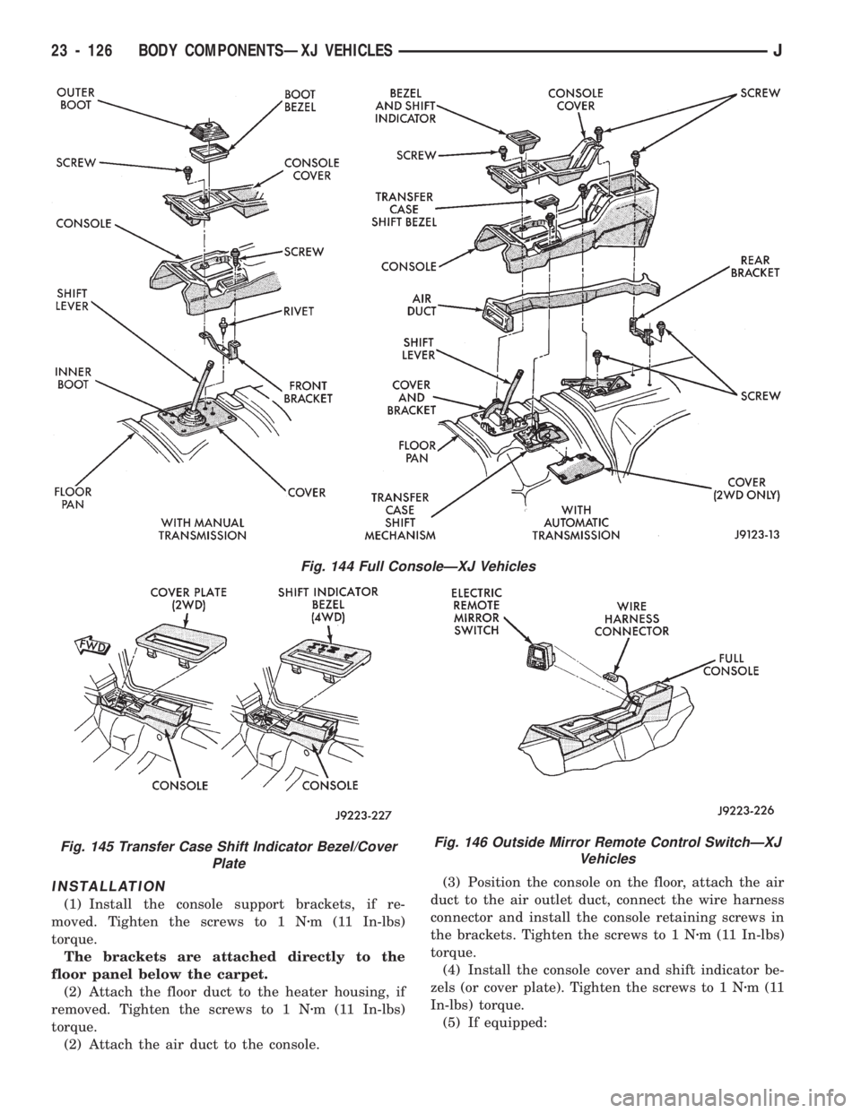
INSTALLATION
(1) Install the console support brackets, if re-
moved. Tighten the screws to 1 Nzm (11 In-lbs)
torque.
The brackets are attached directly to the
floor panel below the carpet.
(2) Attach the floor duct to the heater housing, if
removed. Tighten the screws to 1 Nzm (11 In-lbs)
torque.
(2) Attach the air duct to the console.(3) Position the console on the floor, attach the air
duct to the air outlet duct, connect the wire harness
connector and install the console retaining screws in
the brackets. Tighten the screws to 1 Nzm (11 In-lbs)
torque.
(4) Install the console cover and shift indicator be-
zels (or cover plate). Tighten the screws to 1 Nzm(11
In-lbs) torque.
(5) If equipped:
Fig. 146 Outside Mirror Remote Control SwitchÐXJ
Vehicles
Fig. 144 Full ConsoleÐXJ Vehicles
Fig. 145 Transfer Case Shift Indicator Bezel/Cover
Plate
23 - 126 BODY COMPONENTSÐXJ VEHICLESJ
Page 1668 of 1784
(2) Close all the hand valves.
(3) Connect the red charging hose to the discharge
service valve.
(4) Connect the blue charging hose to the inlet
(suction) service valve.
(5) Discharge the system. Leave the suction and
discharge service valves in the mid-position.
CAUTION: The system must be completely dis-
charged into a recovery device before evacuating. If
the system is still charged, refrigerant can enter
and damage the vacuum pump.
(6) Connect the vacuum pump hose to the vacuum
pump inlet.
(7) Open the low and high pressure control valves
on the charging station.
(8) Start the vacuum pump. Open the vacuum con-
trol valve and note the vacuum reading.
(9) Test the system for leaks as follows:
²Close the manifold hand valves.
²Stop the vacuum pump and observe the vacuum
reading.
²If the system is leak-free, vacuum will hold steady
at the level indicated when the pump was stopped. If
vacuum remains steady for 3-5 minutes, resume and
continue evacuation for a minimum of 30 minutes.
²If the system has a leak, vacuum will fall off or
rapidly drop to a 0 reading. If a leak exists, partially
charge the system. Find and repair the leak and re-
sume evacuation.
(10) Continue evacuating the system for a mini-
mum of 30 minutes after attaining the lowest vac-
uum level.
(11) Fill the station charging cylinder while the
system is evacuating.
(12) Close the vacuum control valve and stop the
vacuum pump.
(13) Observe low pressure gauge to determine if a
system leak exists. If the system is leak-free, the sys-
tem is now ready for charging.
SYSTEM CHARGE
CHARGE CAPACITY
The recommended system charge is 1.1 kg (38 oz.)
of R-12 refrigerant for XJ vehicles and 0.9 kg (32 oz.)
for YJ vehicles.
Add an additional 28 grams (1 fluid oz.) of
compressor oil to the system when a hose, re-
ceiver-drier, condenser, expansion valve or
evaporator core is replaced.
PORTABLE SERVICE STATION
(1) Fill the station charging cylinder. Refrigerant
should be observed rising in the cylinder sight glass.
(2) Slightly open the valve at the top of the cylin-
der when pressure in the charging cylinder and re-frigerant supply tank are equal. This relieves head
pressure allowing refrigerant to continue filling the
cylinder.
(3) Observe the pressure gauge at the top of the
cylinder. Rotate the plastic cover on the cylinder un-
til the pressure heading column corresponds with the
gauge pressure in-line with the sight glass.
FOR EXAMPLE:ÐThe pressure gauge at the top
of the cylinder indicates 483 kPa (70 psi). Locate the
column with the pressure heading of 483 (70) and ro-
tate the cover so the 483 (70) column aligns with the
sight glass.
(4) When refrigerant reaches the correct level in
the sight glass, close the right hand valve at cylinder
base and on the refrigerant drum.
(5) Close the valve at the top of the charging cyl-
inder.
(6) Check for bubbles in the refrigerant using the
cylinder sight glass. If bubbles appear in the refrig-
erant, tilt the charging station rearward momen-
tarily.
(7) Connect the heating element cord to the power
pack receptacle and turn the heater switch ON.
(8) Allow the refrigerant to warm for about 10
minutes while the vacuum pump is operating.
WARNING: WEAR GOGGLES TO PROTECT THE
EYES.
(9) Discharge and evacuate the system.
(10) Close the low pressure valve on the charging
station.
(11) Fully open the left hand refrigerant control
valve at the base of the cylinder and the high pres-
sure valve on the charging station.
(12) Charge the system.
(13) Close the refrigerant control valve and the
high pressure valve on the charging station.
CAUTION: DO NOT permit the liquid level to drop
below 0 on the cylinder sight glass.
(14) Close the manifold gauges after completion of
the charging operation and check the high and low
side pressures.
(15) Check system operation.
CAUTION: DO NOT check system pressures until
the high and low pressure valves on the charging
station are closed. The low pressure gauge could
be damaged if the valves are open.
(16) Close all the valves on the charging station
and close the refrigerant drum valve when all the op-
erations are completed.
(17) Back-seat the service valves by turning them
fully counterclockwise. Install the quick seal caps on
the valves afterward.
JHEATING AND AIR CONDITIONING 24 - 5
Page 1677 of 1784
SERVICE DIAGNOSISÐELECTRICAL
BLOWER CONTROLSÐXJ VEHICLES
DESCRIPTION
The blower motor delivers air to the inside of the
vehicle. Its speed is controlled by the blower switch
and the blower resistors. With the switch in LO, part
of the battery voltage is supplied to the motor
through all of the resistors. The motor runs slowly.
As the blower switch is moved to a higher speed, the
switch allows more voltage to be applied to the
blower motor, which will increase its speed. When
the switch is in HI, the blower resistors are bypassed
and battery voltage is applied directly to the blower
motor. The motor runs at the fastest speed in this
mode.
DIAGNOSIS
Refer to the Group 8W, Wiring Diagrams for com-
plete system schematic.
1. BLOWER MOTOR INOPERATIVE
²Remove and inspect fuse. If the fuse is blown, re-
place fuse.
2. BLOWER MOTOR INOPERATIVE (HI Posi-
tion)
Put the ignition switch in RUN, the select switch
in HEAT and the blower switch on HI.
²Blower motor connector (Terminal A) should be
battery voltage. If not go to next step.
²Blower motor connector (Terminal B) should be 0
ohms. If not, repair wire to ground.
²Blower switch connector (Terminal C) should be
battery voltage. If battery voltage replace blower
switch. If not, replace select switch.
3. BLOWER MOTOR INOPERATIVE (LO, M1
& M2 Positions)
Ignition switch in RUN, select switch in HEAT.
²Blower resistors connector (Terminal D) should be
battery voltage. If not, replace select switch.
²Blower resistors connector (Terminal C) should be
battery voltage. If not, replace blower switch.
²Blower resistors connector (Terminal A) should be
battery voltage. If not, replace blower switch.
²Blower resistors connector (Terminal B) should be
battery voltage. If not, replace blower resistor.
AIR CONDITIONING SYSTEMÐXJ VEHICLES
DESCRIPTION
The A/C Compressor Clutch is belt-driven by the
engine. A clutch, operated by a solenoid, automati-
cally turns the compressor on and off to control evap-
orator icing.
The A/C Compressor Clutch operation is controlled
by several components: the A/C Low-Pressure
Switch, Thermostat Switch, Fuel Pump Relay, A/C
Clutch Relay and the Engine Controller.The A/C low pressure switch opens when there is
not enough refrigerant in the system. When this hap-
pens, voltage is no longer present at the Engine Con-
troller. The Engine Controller will turn off the A/C
clutch relay. With the proper refrigerant level in the
system, the low pressure switch remains closed.
When the evaporator temperature is low enough to
ice the cooling coils, the thermostat switch opens.
The Engine Controller will turn off the A/C clutch.
The thermostat switch closes when the temperature
rises. The Engine Controller will then turn the A/C
clutch relay on again.
DIAGNOSIS
Refer to the Group 8W, Wiring Diagrams for com-
plete system schematic.
With engine running, Engine Controller may delay
A/C clutch up to 30 seconds.
1. A/C COMPRESSOR CLUTCH INOPERA-
TIVE
Clutch connector disconnected.
²Jumper fused test lead, battery to clutch connec-
tor, clutch should operate. If not, replace compressor
clutch assembly.
2. A/C LOW PRESSURE SWITCH
Ignition in RUN, A/C controls in MAX or NORM.
²Low pressure switch connector (Terminal A)
should be battery voltage. If not, repair open to select
switch.
²Low pressure switch connector (Terminal C)
should be battery voltage. If not, check switch resis-
tance and check freon pressure.
3. A/C CLUTCH RELAY
Engine RUNNING, A/C controls in MAX or
NORM.
²Relay connector Pin 4 to ground should be battery
voltage. If not, check fuse F6 in Power Distribution
Center.
²Ground A/C clutch relay (Terminal 5) should have
A/C compressor clutch engagement. If not, check En-
gine Controller Terminals 27, 28 and 34.
HEATING SYSTEMÐYJ VEHICLES
DESCRIPTION
The blower motor circuit begins at a 25 amp fuse
that receives its battery feed from the ignition
switch. From the fuse the circuit extends to a micro-
switch mounted on the heater control.
The micro-switch is normally closed is operated by
a cam on the heater control lever. In all heater con-
trol lever positions, except OFF and VENT, the
blower motor electrical circuit is complete. In the
OFF and VENT positions the cam depresses the mi-
cro-switch lever opening the electrical circuit to the
blower motor.
24 - 14 HEATING AND AIR CONDITIONINGJ