1994 JEEP CHEROKEE heater
[x] Cancel search: heaterPage 259 of 1784
INSTALLATION
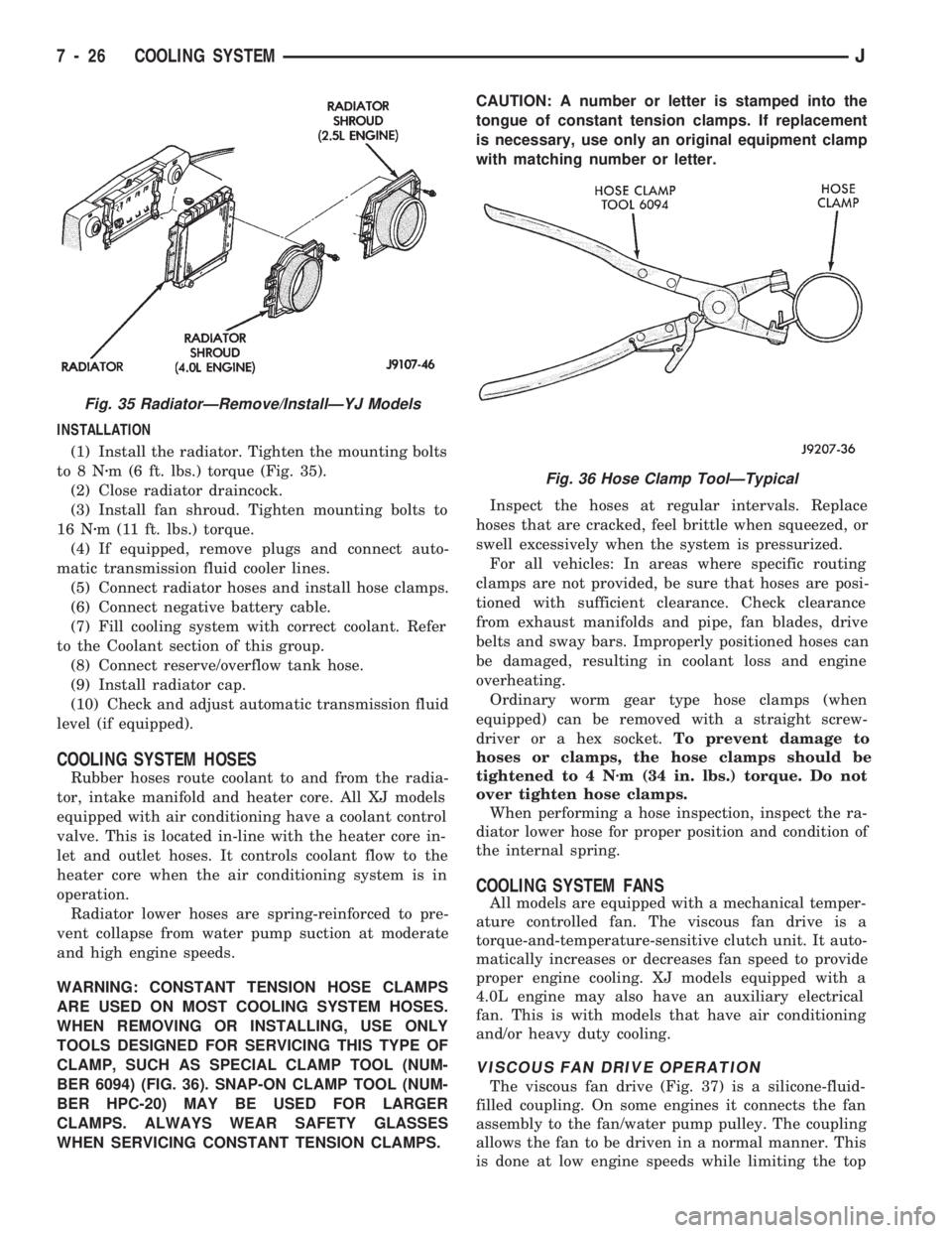
(1) Install the radiator. Tighten the mounting bolts
to8Nzm (6 ft. lbs.) torque (Fig. 35).
(2) Close radiator draincock.
(3) Install fan shroud. Tighten mounting bolts to
16 Nzm (11 ft. lbs.) torque.
(4) If equipped, remove plugs and connect auto-
matic transmission fluid cooler lines.
(5) Connect radiator hoses and install hose clamps.
(6) Connect negative battery cable.
(7) Fill cooling system with correct coolant. Refer
to the Coolant section of this group.
(8) Connect reserve/overflow tank hose.
(9) Install radiator cap.
(10) Check and adjust automatic transmission fluid
level (if equipped).
COOLING SYSTEM HOSES
Rubber hoses route coolant to and from the radia-
tor, intake manifold and heater core. All XJ models
equipped with air conditioning have a coolant control
valve. This is located in-line with the heater core in-
let and outlet hoses. It controls coolant flow to the
heater core when the air conditioning system is in
operation.
Radiator lower hoses are spring-reinforced to pre-
vent collapse from water pump suction at moderate
and high engine speeds.
WARNING: CONSTANT TENSION HOSE CLAMPS
ARE USED ON MOST COOLING SYSTEM HOSES.
WHEN REMOVING OR INSTALLING, USE ONLY
TOOLS DESIGNED FOR SERVICING THIS TYPE OF
CLAMP, SUCH AS SPECIAL CLAMP TOOL (NUM-
BER 6094) (FIG. 36). SNAP-ON CLAMP TOOL (NUM-
BER HPC-20) MAY BE USED FOR LARGER
CLAMPS. ALWAYS WEAR SAFETY GLASSES
WHEN SERVICING CONSTANT TENSION CLAMPS.CAUTION: A number or letter is stamped into the
tongue of constant tension clamps. If replacement
is necessary, use only an original equipment clamp
with matching number or letter.
Inspect the hoses at regular intervals. Replace
hoses that are cracked, feel brittle when squeezed, or
swell excessively when the system is pressurized.
For all vehicles: In areas where specific routing
clamps are not provided, be sure that hoses are posi-
tioned with sufficient clearance. Check clearance
from exhaust manifolds and pipe, fan blades, drive
belts and sway bars. Improperly positioned hoses can
be damaged, resulting in coolant loss and engine
overheating.
Ordinary worm gear type hose clamps (when
equipped) can be removed with a straight screw-
driver or a hex socket.To prevent damage to
hoses or clamps, the hose clamps should be
tightened to 4 Nzm (34 in. lbs.) torque. Do not
over tighten hose clamps.
When performing a hose inspection, inspect the ra-
diator lower hose for proper position and condition of
the internal spring.
COOLING SYSTEM FANS
All models are equipped with a mechanical temper-
ature controlled fan. The viscous fan drive is a
torque-and-temperature-sensitive clutch unit. It auto-
matically increases or decreases fan speed to provide
proper engine cooling. XJ models equipped with a
4.0L engine may also have an auxiliary electrical
fan. This is with models that have air conditioning
and/or heavy duty cooling.
VISCOUS FAN DRIVE OPERATION
The viscous fan drive (Fig. 37) is a silicone-fluid-
filled coupling. On some engines it connects the fan
assembly to the fan/water pump pulley. The coupling
allows the fan to be driven in a normal manner. This
is done at low engine speeds while limiting the top
Fig. 35 RadiatorÐRemove/InstallÐYJ Models
Fig. 36 Hose Clamp ToolÐTypical
7 - 26 COOLING SYSTEMJ
Page 270 of 1784
ENGINE BLOCK HEATER
GENERAL INFORMATION
DESCRIPTION AND OPERATION
An optional engine block heater is available for all
models. The heater is equipped with a power cord.
The cord is attached to an engine compartment com-
ponent with tie-straps. The heater warms the engine
providing easier engine starting and faster warm-up
in low temperatures. The heater is mounted in a core
hole of the engine cylinder block (in place of a freeze
plug) with the heating element immersed in engine
coolant. Connect the power cord to a grounded 110-
120 volt AC electrical outlet with a grounded, three-
wire extension cord.
WARNING: DO NOT OPERATE ENGINE UNLESS
BLOCK HEATER CORD HAS BEEN DISCONNECTED
FROM POWER SOURCE AND SECURED IN PLACE.
BLOCK HEATER SPECIFICATIONS
²2.5L Engine: 115 Volts 400 Watts
²4.0L Engine: 120 Volts 600 Watts
REMOVAL
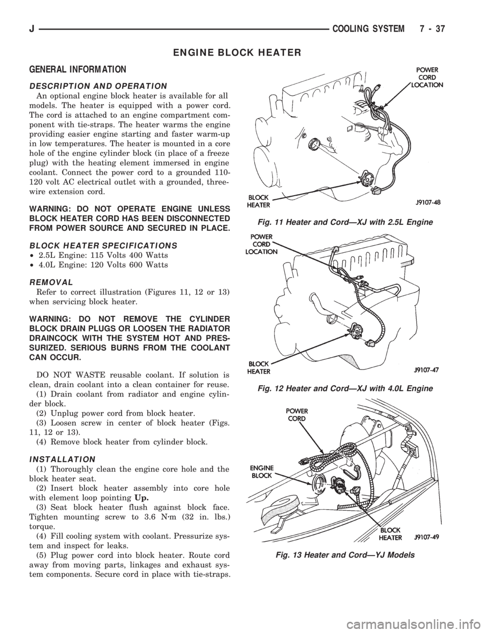
Refer to correct illustration (Figures 11, 12 or 13)
when servicing block heater.
WARNING: DO NOT REMOVE THE CYLINDER
BLOCK DRAIN PLUGS OR LOOSEN THE RADIATOR
DRAINCOCK WITH THE SYSTEM HOT AND PRES-
SURIZED. SERIOUS BURNS FROM THE COOLANT
CAN OCCUR.
DO NOT WASTE reusable coolant. If solution is
clean, drain coolant into a clean container for reuse.
(1) Drain coolant from radiator and engine cylin-
der block.
(2) Unplug power cord from block heater.
(3) Loosen screw in center of block heater (Figs.
11, 12 or 13).
(4) Remove block heater from cylinder block.
INSTALLATION
(1) Thoroughly clean the engine core hole and the
block heater seat.
(2) Insert block heater assembly into core hole
with element loop pointingUp.
(3) Seat block heater flush against block face.
Tighten mounting screw to 3.6 Nzm (32 in. lbs.)
torque.
(4) Fill cooling system with coolant. Pressurize sys-
tem and inspect for leaks.
(5) Plug power cord into block heater. Route cord
away from moving parts, linkages and exhaust sys-
tem components. Secure cord in place with tie-straps.
Fig. 11 Heater and CordÐXJ with 2.5L Engine
Fig. 12 Heater and CordÐXJ with 4.0L Engine
Fig. 13 Heater and CordÐYJ Models
JCOOLING SYSTEM 7 - 37
Page 355 of 1784

INSTRUMENT PANEL REPLACEMENT (Fig. 9)
(1) Disconnect negative cable from battery.
(2) Remove:
²Parking brake release handle
²lower heat/AC duct below steering column
²ash receiver²lower instrument panel (Fig. 10)
²cluster bezel
²cluster assembly
²clock (if equipped)
²radio and heater control panel
²instrument panel switches
²headlamp switch
Fig. 8 Gear Selector Indicator
Fig. 9 Instrument Panel Exploded View
Fig. 10 Lower Instrument Panel Removal/Installation
8E - 8 XJ INSTRUMENT PANEL AND GAUGESJ
Page 567 of 1784
Wiring Diagram Name Sheet Number
Left Fog Lamp.............................27
Left Headlamp.............................27
Left Park and Turn Signal Lamp.................27
Left Side Marker Lamp.......................27
Right Fog Lamp............................28
Right Headlamp............................28
Right Park and Turn Signal Lamp................28
Right Side Marker Lamp......................28
Fuel Gauge................................44
Fuel Injection Ignition System
2.5L Engine.................11, 12, 13, 14, 15, 16
Automatic Shut Down Relay....................11
Camshaft Position Sensor.....................12
Crankshaft Position Sensor.....................12
Data Link Connector.........................13
Engine Coolant Temperature Sensor...............15
Fuel Injectors.............................14
Fuel Pump Relay...........................11
Heated Oxygen Sensor.......................11
Idle Air Control Motor........................14
Ignition Coil..............................13
Intake Air Temperature Sensor..................15
MAP Sensor..............................15
Power Steering Switch.......................14
Powertrain Control Module (PCM) . . .11, 12, 13, 14, 15, 16
Throttle Position (Sensor).....................15
Vehicle Speed Sensor........................12
Fuel Injection Ignition System
4.0L Engine.................17, 18, 19, 20, 21, 22
Automatic Shut Down Relay....................17
Camshaft Position Sensor.....................18
Crankshaft Position Sensor.....................18
Data Link Connector.........................19
Engine Coolant Temperature Sensor...............21
Fuel Injectors.............................20
Fuel Pump Relay...........................17
Heated Oxygen Sensor.......................17
Idle Air Control Motor........................20
Ignition Coil..............................19
Intake Air Temperature Sensor..................21
MAP Sensor..............................21
Powertrain Control Module (PCM) . . .17, 18, 19, 20, 21, 22
Throttle Position (Sensor).....................21
Vehicle Speed Sensor........................18
Fuel Injectors............................14, 20
Fuel Pump Relay..........................11, 17
Fuel Tank System............................55
Fuel Tank Sending Unit.........................55
Fuse Application Chart........................1,2
Fuses
1 .................................2,10,37
3 ..............................1,30,34,36
4 .................................2,10,34
5 ..............................2,10,13,19
6 .................................1,30,53
7 ..............................2,10,24,46
8 ...................................1,29
9 .................................2,10,36Wiring Diagram Name Sheet Number
10 ...................................1,31
11 .............................2,10,38,39
12 ...........................2,10,47,48,50
F13 ..................................2,58
F15 ..............................2,4,6,33
F16 ............................2,4,6,8,35
Fuse Panel..............................61, 62
Gauge Package Connector.......................43
Gauges
Electronic Speedometer.......................42
Electronic Tachometer........................42
Engine Coolant Temperature Gauge...............44
Engine Oil Pressure Gauge.....................44
Fuel Gauge...............................44
Voltmeter................................44
Generator................................3,5
Hazard Signal Flasher..........................34
Headlamps.........................25, 26, 27, 28
Headlamp Switch........................1,29,30
Dimmer Switch............................29
Headlamp Switch...........................29
Heated Oxygen Sensor......................11, 17
Heated Rear Window Relay......................54
Heated Rear Window Switch.....................53
Heated Rear Window System..................53, 54
Heated Rear Window Grid.....................53
Heated Rear Window Relay....................54
Heated Rear Window Switch....................53
Timer..................................54
Heater Control Panel Illumination..................32
Heater System..............................47
Blower Motor.............................47
Blower Resistor............................47
Blower Switch.............................47
Heater/Off Switch...........................47
Horn.....................................33
Horn Brush/Slip Ring........................33
Horn Relay...............................33
Horn Switch..............................33
Hydraulic Actuation Unit........................58
Idle Air Control Motor.......................14, 20
Ignition Coil.............................13, 19
Ignition Key Warning Switch.....................36
Ignition Switch..........................2,9,10
Instrument Panel Illumination Lamps................32
Intake Air Temperature Sensor.................15, 21
Intermittent Wiper Module.......................40
Intermittent Wiper System....................39, 40
Intermittent Wiper Module.....................40
Park Switch..............................39
Washer Pump.............................39
Wiper Motor..............................39
Wiper/Washer Switch........................40
W/Wiper Circuit Breaker (5.3 Amp)...............39
Lamps
Center High Mounted Stop Lamps................52
Dome Lamp..............................35
Instrument Panel Illumination Lamp...............32
8W - 74 WIRING DIAGRAMSJ
Page 568 of 1784
Wiring Diagram Name Sheet Number
Left Back-Up Lamp..........................51
Left Courtesy Lamp.........................35
Left Fog Lamp..........................25, 27
Left Headlamp..........................25, 27
Left Park and Turn Signal Lamp..............25, 27
Left Side Marker Lamp....................25, 27
Left Tail, Stop and Turn Signal Lamp..............51
Right Back-Up Lamp.........................52
Right Courtesy Lamp........................35
Right Fog Lamp.........................26, 28
Right Headlamp.........................26, 28
Right Park and Turn Signal Lamp.............26, 28
Right Side Marker Lamp...................26, 28
Right Tail, Stop and Turn Signal Lamp.............52
Underhood Lamp............................8
Left Back-Up Lamps..........................51
Left Courtesy Lamp...........................35
Left Fog Lamp...........................25, 27
Left Front Door Jamb Switch.....................35
Left Front Speaker............................46
Left Halo Speaker............................46
Left Headlamp............................25, 27
Left Park and Turn Signal Lamp................25, 27
Left Side Marker Lamp......................25, 27
Left Tail, Stop and Turn Signal Lamp...............51
MAP Sensor.............................15, 21
Mercury Switch..............................8
Modules
ABS Control Module....................57, 58, 59
Buzzer Module.............................36
Daytime Running Lamp Module.................28
Intermittent Wiper Module.....................40
Motors
Blower Motor.............................47
Engine Starter Motor.........................7
Idle Air Control Motor.....................14, 20
Rear Wiper Motor..........................37
Wiper Motor...........................38, 39
Oil Pressure and Temp System...................23
Panel Lamp Dimmer Switch......................1
Panel Lamps.............................31, 32
Accessory Illumination........................32
Heater Control Panel Illumination.................32
Panel Lamp Dimmer Switch....................31
Transmission Range Illumination.................32
Park Brake Switch.............................9
Park/Neutral Position Switch......................7
Part Throttle EMCC 3-Speed Automatic Transmission.....56
Part Throttle EMCC Relay.......................56
Part Throttle EMCC Solenoid.....................56
Power Distribution Center.................1,4,6,57
Power Distribution Center Identification Cover..........67
Power Distribution Center Relays..................68
Power Steering Switch.........................14
Powertrain Control Module............11-22, 48, 49, 56
Powertrain Control Module Connector (2.5L Engine)......63
Powertrain Control Module Connector (4.0L Engine)......64
Provisions for A/C (2.5L).......................48Wiring Diagram Name Sheet Number
Radio Illumination Relay........................45
Radio System............................45, 46
Electrically Tuned Radio with Clock...............45
Left Front Speaker..........................46
Left Halo Speaker...........................46
Radio Illumination Relay......................45
Right Front Speaker.........................46
Right Halo Speaker..........................46
Rear Lighting............................51, 52
Center High Mounted Stop Lamp................52
Left Back-Up Lamp..........................51
Left Tail, Stop & Turn Signal Lamp & License Lamp....51
Right Back-Up Lamp.........................52
Right Tail, Stop & Turn Signal Lamp..............52
Rear Wiper/Washer System......................37
Rear Wiper Motor..........................37
Rear Wiper Switch..........................37
Washer Pump.............................37
Relays
A/C ....................................49
ABS Motor Pump Relay.......................57
ABS Power Relay...........................57
Automatic Shut Down Relay.................11, 17
EMCC...................................56
Engine Starter Relay..........................7
Fog Lamp Relays...........................30
Fuel Pump Relay........................11, 17
Heated Rear Window Relay....................54
Horn Relay...............................33
Radio Illumination Relay......................45
Right Back-Up Lamp..........................52
Right Courtesy Lamp..........................35
Right Fog Lamp...........................26, 28
Right Front Door Jamb Switch....................35
Right Front Speaker...........................46
Right Halo Speaker...........................46
Right Headlamp...........................26, 28
Right Park and Turn Signal...................26, 28
Right Side Marker Lamp.....................26, 28
Right Tail, Stop and Turn Signal Lamp..............52
Seat Belt/Ignition Key Warning Buzzer...............36
Seat Belt Switch.............................36
Sensors
ABS Accelerator Sensor.......................59
Brake Pedal Travel Sensor.....................57
Camshaft Position Sensor...................12, 18
Crankshaft Position Sensor..................12, 18
Engine Coolant Temperature Sensor............15, 21
Heated Oxygen Sensor.....................11, 17
Intake Air Temperature Sensor................15, 21
MAP Sensor...........................15, 21
Pump Motor Sensor.........................57
Throttle Position (Sensor)...................15, 21
Vehicle Speed Sensor.....................12, 18
Wheel Sensors............................59
Speakers..................................46
Speedometer...............................42
JWIRING DIAGRAMS 8W - 75
Page 569 of 1784
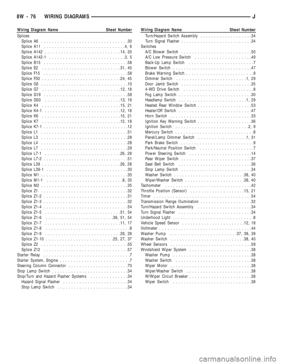
Wiring Diagram Name Sheet Number
Splices
Splice A6................................30
Splice A11..............................4,6
Splice A142............................14, 20
Splice A142-1............................3,5
Splice B15...............................58
Splice E2.............................31, 45
Splice F15...............................58
Splice F30.............................24, 45
Splice G5................................10
Splice G7.............................12, 18
Splice G19...............................58
Splice G50............................13, 19
Splice K4.............................15, 21
Splice K4-1............................12, 18
Splice K6.............................15, 21
Splice K7.............................12, 18
Splice K7-1...............................12
Splice L1................................51
Splice L3................................28
Splice L4................................28
Splice L7................................29
Splice L7-1............................26, 28
Splice L7-2...............................51
Splice L39.............................26, 28
Splice L39-1..............................30
Splice M1................................35
Splice M1-1............................8,35
Splice M2................................35
Splice Z1................................32
Splice Z1-2...............................31
Splice Z1-3...............................32
Splice Z1-4...............................54
Splice Z1-5............................51, 54
Splice Z1-6.........................36, 51, 54
Splice Z1-7............................11, 17
Splice Z1-8...............................8
Splice Z1-9............................26, 28
Splice Z1-10.........................25, 27, 37
Splice Z2................................55
Splice Z12...............................57
Starter Relay................................7
Starter System, Engine..........................7
Steering Column Connector......................70
Stop Lamp Switch............................34
Stop/Turn and Hazard Flasher Systems..............34
Hazard Signal Flasher........................34
Stop Lamp Switch..........................34Wiring Diagram Name Sheet Number
Turn/Hazard Switch Assembly...................34
Turn Signal Flasher..........................34
Switches
A/C Blower Switch..........................50
A/C Low Pressure Switch.....................49
Back-Up Lamp Switch........................7
Blower Switch.............................47
Brake Warning Switch.........................9
Dimmer Switch..........................1,29
Door Jamb Switch..........................35
4-WD Drive Switch..........................8
Fog Lamp Switch...........................30
Headlamp Switch.........................1,29
Heated Rear Window Switch....................53
Heater/Off Switch...........................47
Horn Switch..............................33
Ignition Key Warning Switch....................36
Ignition Switch...........................2,9
Mercury Switch.............................8
Panel/Lamp Dimmer Switch..................1,31
Park Brake Switch...........................9
Park/Neutral Position Switch....................7
Power Steering Switch.......................14
Rear Wiper Switch..........................37
Seat Belt Switch...........................36
Stop Lamp Switch..........................34
Washer Switch..........................38, 40
Wiper/Washer Switch......................38, 40
Tachometer................................42
Throttle Position (Sensor)....................15, 21
Timer....................................54
Transmission Range Illumination...................32
Turn/Hazard Switch Assembly....................34
Turn Signal Flasher...........................34
Underhood Light..............................8
Vehicle Speed Sensor.......................12, 18
Voltmeter..................................44
Washer Pump.........................37, 38, 39
Washer Switch...........................38, 40
Wheel Sensors..............................59
Windshield Wiper System.......................38
Washer Pump.............................38
Washer Switch............................38
Wiper Motor..............................38
Wiper/Washer Switch........................38
W/Wiper Circuit Breaker.......................38
Wiper Switch.............................38
8W - 76 WIRING DIAGRAMSJ
Page 642 of 1784
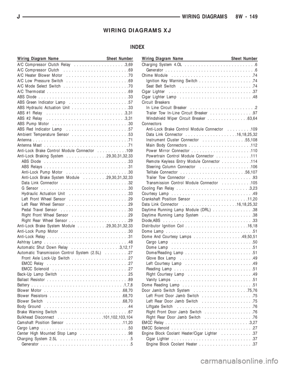
WIRING DIAGRAMS XJ
INDEX
Wiring Diagram Name Sheet Number
A/C Compressor Clutch Relay...................3,69
A/C Compressor Clutch........................69
A/C Heater Blower Motor.......................70
A/C Low Pressure Switch.......................69
A/C Mode Select Switch........................70
A/C Thermostat..............................69
ABS Diode.................................33
ABS Green Indicator Lamp......................57
ABS Hydraulic Actuation Unit.....................33
ABS #1 Relay.............................3,31
ABS #2 Relay.............................3,31
ABS Pump Motor............................30
ABS Red Indicator Lamp.......................57
Ambient Temperature Sensor.....................53
Antenna...................................71
Antenna Mast...............................71
Anti-Lock Brake Control Module Connector...........109
Anti-Lock Braking System...............29,30,31,32,33
ABS Diode...............................33
ABS Relays...............................31
Anti-Lock Pump Motor.......................30
Anti-Lock Brake System Module.........29,30,31,32,33
Data Link Connector.........................32
G Sensor................................30
Hydraulic Actuation Unit......................33
Left Front Wheel Sensor......................29
Left Rear Wheel Sensor.......................29
Pedal Travel Sensor.........................30
Right Front Wheel Sensor.....................29
Right Rear Wheel Sensor......................29
Anti-Lock Brake System Module...........29,30,31,32,33
Anti-Lock Pump Motor.........................30
Anti-Lock Relay..............................31
Ashtray Lamp...............................48
Automatic Shut Down Relay..................3,12,17
Automatic Transmission Control System (2.5L).........27
Front Axle Lock-Up Switch.....................27
EMCC Relay..............................27
EMCC Solenoid............................27
Back-Up Lamp Switch.........................25
Ballast Resistor..............................89
Battery..................................1,7,8
Blower Motor.............................68,70
Blower Resistors...........................68,70
Blower Switch............................68,70
Body Ground...............................44
Brake Warning Switch.........................67
Bulkhead Disconnect.................101,102,103,104
Camshaft Position Sensor.....................11,20
Cargo Lamp................................50
Center High Mounted Stop Lamp..................98
Charging System 2.5L..........................5
Generator.................................5Wiring Diagram Name Sheet Number
Charging System 4.OL..........................6
Generator.................................6
Chime Module..............................74
Ignition Key Warning Switch....................74
Seat Belt Switch...........................74
Cigar Lighter...............................37
Cigar Lighter Lamp...........................48
Circuit Breakers
In Line Circuit Breaker........................2
Trailer Tow In-Line Circuit Breaker................97
Windshield Wiper Circuit Breaker...............63,64
Connectors
Anti-Lock Brake Control Module Connector.........109
Data Link Connector...................16,18,25,32
Instrument Cluster Connector................55,108
Main Body Connectors.......................112
Power Mirror Connector......................110
Powertrain Control Module Connector.............111
Remote Keyless Entry Module Connector...........114
Steering Column Connector...................106
Telltale Connector........................56,107
Trailer Tow Connector........................93
Transmission Control Module Connector...........105
Cooling Fan Relay...........................3,23
Courtesy Lamp..............................49
Crankshaft Position Sensor....................11,20
Data Link Connector....................16,18,25,32
Daytime Running Lamp Module (DRL)...............38
Daytime Running Lamp System...................38
Diode,ABS.................................33
Distributor Ignition Coil.......................16,18
Dome Lamp................................51
Dome And Courtesy Lamps..................49,50,51
Cargo Lamp..............................50
Dome Lamp..............................51
Dome/Reading Lamp.........................51
Glove Box Lamp...........................49
Left Courtesy Lamp.........................49
Reading Lamp.............................51
Right Courtesy Lamp........................49
Vanity Lamps.............................51
Dome Reading Lamp..........................51
Door Jamb Switch System....................75,76
Left Front Door Jamb Switch...................75
Left Rear Door Jamb Switch...................75
Liftgate Switch............................76
Right Front Door Jamb Switch..................76
Right Rear Door Jamb Switch..................76
EMCC Relay...............................3,27
EMCC Solenoid..............................27
Engine Block Coolant Heater/Cigar Lighter............37
Cigar Lighter..............................37
Engine Block Coolant Heater....................37
JWIRING DIAGRAMS 8W - 149
Page 643 of 1784
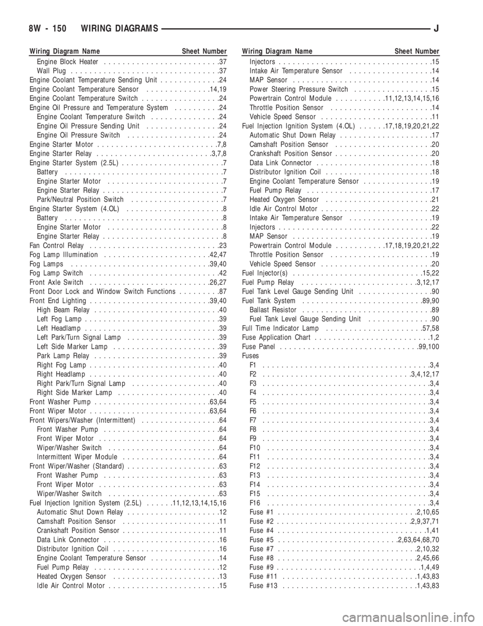
Wiring Diagram Name Sheet Number
Engine Block Heater.........................37
Wall Plug................................37
Engine Coolant Temperature Sending Unit.............24
Engine Coolant Temperature Sensor..............14,19
Engine Coolant Temperature Switch.................24
Engine Oil Pressure and Temperature System..........24
Engine Coolant Temperature Switch...............24
Engine Oil Pressure Sending Unit................24
Engine Oil Pressure Switch....................24
Engine Starter Motor..........................7,8
Engine Starter Relay.........................3,7,8
Engine Starter System (2.5L)......................7
Battery..................................7
Engine Starter Motor.........................7
Engine Starter Relay..........................7
Park/Neutral Position Switch....................7
Engine Starter System (4.OL).....................8
Battery..................................8
Engine Starter Motor.........................8
Engine Starter Relay..........................8
Fan Control Relay............................23
Fog Lamp Illumination.......................42,47
Fog Lamps..............................39,40
Fog Lamp Switch............................42
Front Axle Switch..........................26,27
Front Door Lock and Window Switch Functions.........87
Front End Lighting..........................39,40
High Beam Relay...........................40
Left Fog Lamp.............................39
Left Headlamp.............................39
Left Park/Turn Signal Lamp....................39
Left Side Marker Lamp.......................39
Park Lamp Relay...........................39
Right Fog Lamp............................40
Right Headlamp............................40
Right Park/Turn Signal Lamp...................40
Right Side Marker Lamp......................40
Front Washer Pump.........................63,64
Front Wiper Motor..........................63,64
Front Wipers/Washer (Intermittent).................64
Front Washer Pump.........................64
Front Wiper Motor..........................64
Wiper/Washer Switch........................64
Intermittent Wiper Module.....................64
Front Wiper/Washer (Standard)....................63
Front Washer Pump.........................63
Front Wiper Motor..........................63
Wiper/Washer Switch........................63
Fuel Injection Ignition System (2.5L)......11,12,13,14,15,16
Automatic Shut Down Relay....................12
Camshaft Position Sensor.....................11
Crankshaft Position Sensor.....................11
Data Link Connector.........................16
Distributor Ignition Coil.......................16
Engine Coolant Temperature Sensor...............14
Fuel Pump Relay...........................12
Heated Oxygen Sensor.......................13
Idle Air Control Motor........................15Wiring Diagram Name Sheet Number
Injectors.................................15
Intake Air Temperature Sensor..................14
MAP Sensor..............................14
Power Steering Pressure Switch.................15
Powertrain Control Module...........11,12,13,14,15,16
Throttle Position Sensor......................14
Vehicle Speed Sensor........................11
Fuel Injection Ignition System (4.OL)......17,18,19,20,21,22
Automatic Shut Down Relay....................17
Camshaft Position Sensor.....................20
Crankshaft Position Sensor.....................20
Data Link Connector.........................18
Distributor Ignition Coil.......................18
Engine Coolant Temperature Sensor...............19
Fuel Pump Relay...........................17
Heated Oxygen Sensor.......................21
Idle Air Control Motor........................22
Intake Air Temperature Sensor..................19
Injectors.................................22
MAP Sensor..............................19
Powertrain Control Module...........17,18,19,20,21,22
Throttle Position Sensor......................19
Vehicle Speed Sensor........................20
Fuel Injector(s)............................15,22
Fuel Pump Relay.........................3,12,17
Fuel Tank Level Gauge Sending Unit................90
Fuel Tank System..........................89,90
Ballast Resistor............................89
Fuel Tank Level Gauge Sending Unit..............90
Full Time Indicator Lamp.....................57,58
Fuse Application Chart.........................1,2
Fuse Panel..............................99,100
Fuses
F1 ....................................3,4
F2 ................................3,4,12,17
F3 ....................................3,4
F4 ....................................3,4
F5 ....................................3,4
F6 ....................................3,4
F7 ....................................3,4
F8 ....................................3,4
F9 ....................................3,4
F10 ...................................3,4
F11 ...................................3,4
F12 ...................................3,4
F13 ...................................3,4
F14 ...................................3,4
F15 ...................................3,4
F16 ...................................3,4
Fuse #1..............................2,10,65
Fuse #2.............................2,9,37,71
Fuse #4................................1,41
Fuse #5..........................2,63,64,68,70
Fuse #7..............................2,10,32
Fuse #8..............................2,45,66
Fuse #9...............................1,4,49
Fuse #11.............................1,43,83
Fuse #13.............................1,43,83
8W - 150 WIRING DIAGRAMSJ