1994 JEEP CHEROKEE clutch
[x] Cancel search: clutchPage 231 of 1784
Check flywheel runout if misalignment is sus-
pected. Runout should not exceed 0.08 mm (0.003
in.). Measure runout at the outer edge of the fly-
wheel face with a dial indicator. Mount the dial indi-
cator on a stud installed in place of one of the
flywheel attaching bolts.
Clean the crankshaft flange before mounting the
flywheel. Dirt and grease on the flange surface may
cock the flywheel causing excessive runout.
Check condition of the flywheel hub and attaching
bolts. Replace the flywheel if the hub exhibits cracks
in the area of the attaching bolt holes.
Install new attaching bolts whenever the flywheel
is replaced and use Mopar Lock N' Seal, or Loctite
242 on the replacement bolt threads.
Recommended flywheel bolt torques are:
²142 Nzm (105 ft. lbs.) for 6-cylinder flywheels
²68 Nzm (50 ft. lbs.) plus an additional turn of 60É
for 4-cylinder flywheels
Inspect the teeth on the starter ring gear.If the
teeth are worn or damaged, the flywheel should
be replaced as an assembly. This is the recom-
mended and preferred method of repair.
In cases where a new flywheel is not readily avail-
able, a replacement ring gear can be installed. How-
ever, the following precautions must be observed to
avoid damaging the flywheel and replacement gear.
(a) Mark position of the old gear for alignment
reference on the flywheel. Use a scriber for this
purpose.
(b) Wear protective goggles or approved safety
glasses. Also wear heat resistent gloves when han-
dling a heated ring gear.
(c) Remove the old gear by cutting most of the
way through it (at one point) with an abrasive cut-
off wheel. Then complete removal with a cold chisel
or punch.(d) The ring gear is a shrink fit on the flywheel.
This means the gear must be expanded by heating
in order to install it.The method of heating and
expanding the gear is extremely important.
Every surface of the gear must be heated at the
same time to produce uniform expansion. An oven
or similar enclosed heating device must be used.
Temperature required for uniform expansion is ap-
proximately 375É F.
CAUTION: Do not use an oxy/acetylene torch to re-
move the old gear, or to heat and expand a new
gear. The high temperature of the torch flame can
cause localized heating that will damage the fly-
wheel. In addition, using the torch to heat a replace-
ment gear will cause uneven heating and
expansion. The torch flame can also anneal the
gear teeth resulting in rapid wear and damage after
installation.
(e) The heated gear must be installed evenly to
avoid misalignment or distortion. A shop press and
suitable press plates should be used to install the
gear if at all possible.
(f) Be sure to wear eye and hand protection.
Heat resistent gloves and safety goggles are needed
for personal safety. Also use metal tongs, vise grips,
or similar tools to position the gear as necessary
for installation.
(g) Allow the flywheel and ring gear to cool down
before installation. Set the assembly on a work-
bench and let it cool in normal shop air.
CAUTION: Do not use water, or compressed air to
cool the flywheel. The rapid cooling produced by
water or compressed air can distort, or crack the
gear and flywheel.
6 - 16 CLUTCH SERVICEJ
Page 232 of 1784
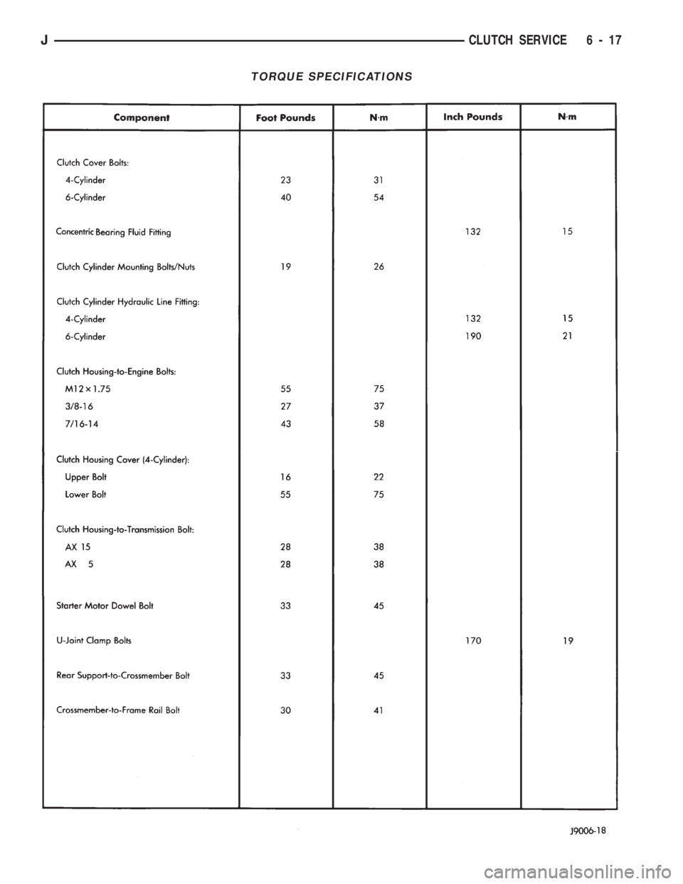
TORQUE SPECIFICATIONS
JCLUTCH SERVICE 6 - 17
Page 259 of 1784
INSTALLATION
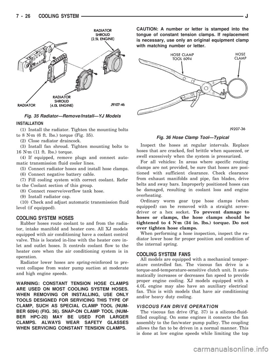
(1) Install the radiator. Tighten the mounting bolts
to8Nzm (6 ft. lbs.) torque (Fig. 35).
(2) Close radiator draincock.
(3) Install fan shroud. Tighten mounting bolts to
16 Nzm (11 ft. lbs.) torque.
(4) If equipped, remove plugs and connect auto-
matic transmission fluid cooler lines.
(5) Connect radiator hoses and install hose clamps.
(6) Connect negative battery cable.
(7) Fill cooling system with correct coolant. Refer
to the Coolant section of this group.
(8) Connect reserve/overflow tank hose.
(9) Install radiator cap.
(10) Check and adjust automatic transmission fluid
level (if equipped).
COOLING SYSTEM HOSES
Rubber hoses route coolant to and from the radia-
tor, intake manifold and heater core. All XJ models
equipped with air conditioning have a coolant control
valve. This is located in-line with the heater core in-
let and outlet hoses. It controls coolant flow to the
heater core when the air conditioning system is in
operation.
Radiator lower hoses are spring-reinforced to pre-
vent collapse from water pump suction at moderate
and high engine speeds.
WARNING: CONSTANT TENSION HOSE CLAMPS
ARE USED ON MOST COOLING SYSTEM HOSES.
WHEN REMOVING OR INSTALLING, USE ONLY
TOOLS DESIGNED FOR SERVICING THIS TYPE OF
CLAMP, SUCH AS SPECIAL CLAMP TOOL (NUM-
BER 6094) (FIG. 36). SNAP-ON CLAMP TOOL (NUM-
BER HPC-20) MAY BE USED FOR LARGER
CLAMPS. ALWAYS WEAR SAFETY GLASSES
WHEN SERVICING CONSTANT TENSION CLAMPS.CAUTION: A number or letter is stamped into the
tongue of constant tension clamps. If replacement
is necessary, use only an original equipment clamp
with matching number or letter.
Inspect the hoses at regular intervals. Replace
hoses that are cracked, feel brittle when squeezed, or
swell excessively when the system is pressurized.
For all vehicles: In areas where specific routing
clamps are not provided, be sure that hoses are posi-
tioned with sufficient clearance. Check clearance
from exhaust manifolds and pipe, fan blades, drive
belts and sway bars. Improperly positioned hoses can
be damaged, resulting in coolant loss and engine
overheating.
Ordinary worm gear type hose clamps (when
equipped) can be removed with a straight screw-
driver or a hex socket.To prevent damage to
hoses or clamps, the hose clamps should be
tightened to 4 Nzm (34 in. lbs.) torque. Do not
over tighten hose clamps.
When performing a hose inspection, inspect the ra-
diator lower hose for proper position and condition of
the internal spring.
COOLING SYSTEM FANS
All models are equipped with a mechanical temper-
ature controlled fan. The viscous fan drive is a
torque-and-temperature-sensitive clutch unit. It auto-
matically increases or decreases fan speed to provide
proper engine cooling. XJ models equipped with a
4.0L engine may also have an auxiliary electrical
fan. This is with models that have air conditioning
and/or heavy duty cooling.
VISCOUS FAN DRIVE OPERATION
The viscous fan drive (Fig. 37) is a silicone-fluid-
filled coupling. On some engines it connects the fan
assembly to the fan/water pump pulley. The coupling
allows the fan to be driven in a normal manner. This
is done at low engine speeds while limiting the top
Fig. 35 RadiatorÐRemove/InstallÐYJ Models
Fig. 36 Hose Clamp ToolÐTypical
7 - 26 COOLING SYSTEMJ
Page 299 of 1784
4.0L STARTER GENERAL INFORMATION
The Mitsubishi starter motor is a light-weight unit
featuring a planetary gear drive and permanent
magnets for current induction.
The planetary gear drive is splined to both the ar-
mature shaft and overrunning clutch. Starter torque
is transmitted to the overrunning clutch pinion
through the planetary gears which provide higher ro-
tational speeds.
The starter magnetic field is produced by six per-
manent magnets. The magnets are mounted in the
starter frame and positioned according to polarity.
They are permanently attached to the frame and are
not removable.
The starter motor is activated by a solenoid
mounted on the overrunning clutch housing.
This unit is highly sensitive to hammering, shocks,
and external pressure.
CAUTION: The starter motor MUST NOT BE
CLAMPED in a vise by the starter frame. Doing so
may damage the magnets. It may be clamped by the
mounting flange ONLY.
CAUTION: Do not connect the starter motor incor-
rectly when performing tests. The magnets may be
damaged and rendered unserviceable.
²Ensure cleanliness when performing repairs.
²Metal chips are attracted by the magnets and may
not be completely removed from the starter frame.
Chips in the ring gear can lead to failure of the
starter.
4.0L STARTER MOTOR REMOVAL/INSTALLATION
(1) Disconnect negative cable from battery.
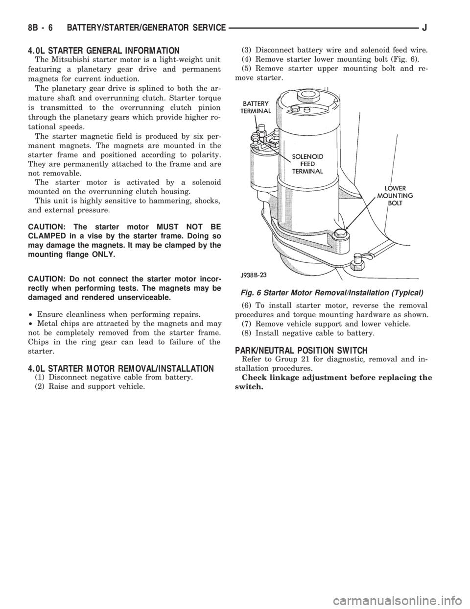
(2) Raise and support vehicle.(3) Disconnect battery wire and solenoid feed wire.
(4) Remove starter lower mounting bolt (Fig. 6).
(5) Remove starter upper mounting bolt and re-
move starter.
(6) To install starter motor, reverse the removal
procedures and torque mounting hardware as shown.
(7) Remove vehicle support and lower vehicle.
(8) Install negative cable to battery.
PARK/NEUTRAL POSITION SWITCH
Refer to Group 21 for diagnostic, removal and in-
stallation procedures.
Check linkage adjustment before replacing the
switch.
Fig. 6 Starter Motor Removal/Installation (Typical)
8B - 6 BATTERY/STARTER/GENERATOR SERVICEJ
Page 390 of 1784
VEHICLE SPEED CONTROL SYSTEM
CONTENTS
page page
SERVICE PROCEDURES................... 9TEST PROCEDURES...................... 5
GENERAL INFORMATION
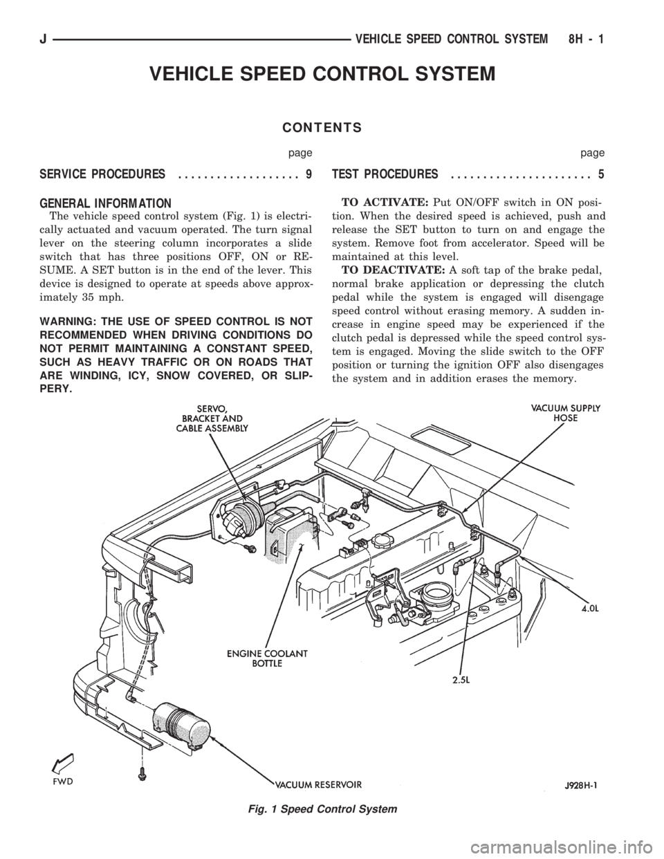
The vehicle speed control system (Fig. 1) is electri-
cally actuated and vacuum operated. The turn signal
lever on the steering column incorporates a slide
switch that has three positions OFF, ON or RE-
SUME. A SET button is in the end of the lever. This
device is designed to operate at speeds above approx-
imately 35 mph.
WARNING: THE USE OF SPEED CONTROL IS NOT
RECOMMENDED WHEN DRIVING CONDITIONS DO
NOT PERMIT MAINTAINING A CONSTANT SPEED,
SUCH AS HEAVY TRAFFIC OR ON ROADS THAT
ARE WINDING, ICY, SNOW COVERED, OR SLIP-
PERY.TO ACTIVATE:Put ON/OFF switch in ON posi-
tion. When the desired speed is achieved, push and
release the SET button to turn on and engage the
system. Remove foot from accelerator. Speed will be
maintained at this level.
TO DEACTIVATE:A soft tap of the brake pedal,
normal brake application or depressing the clutch
pedal while the system is engaged will disengage
speed control without erasing memory. A sudden in-
crease in engine speed may be experienced if the
clutch pedal is depressed while the speed control sys-
tem is engaged. Moving the slide switch to the OFF
position or turning the ignition OFF also disengages
the system and in addition erases the memory.
Fig. 1 Speed Control System
JVEHICLE SPEED CONTROL SYSTEM 8H - 1
Page 391 of 1784
TO RESUME AFTER BRAKING:After disen-
gaging the speed control system by tapping the brake
pedal or clutch pedal, push the RESUME/ACCEL
button to return vehicle to the previously set speed.
SET/COAST:Speed can be decreased by holding
SET button against stop until desired speed is at-
tained. Releasing the button engages the system at
that speed. A decrease in speed also can be attained
by tapping brake pedal lightly disengaging system.
When desired speed has been obtained push and re-
lease SET button.
TO ACCELERATE FOR PASSING:Depress ac-
celerator as needed. When passing is completed, re-lease accelerator and vehicle will return to previous
speed setting. There may be a slight (3-7 mph) speed
loss before the vehicle recovers to the set speed.
TAP-UP:When the speed control system is en-
gaged, tapping the RESUME/ACCEL button will in-
crease the speed setting by 2 mph (3 km/h). The
system will respond to multiple tap-ups.
TO ACCELERATE:While speed control is en-
gaged, hold the RESUME/ACCEL button depressed
and release at a new desired speed. This will allow
the vehicle to accelerate and set at a higher speed
setting.
8H - 2 VEHICLE SPEED CONTROL SYSTEMJ
Page 397 of 1784
(4) Slide speed switch to RESUME/ACCEL and
hold it there. Vehicle should accelerate.
(5) Release speed switch back to ON. Vehicle will
hold the new faster speed, if SET speed button has
been pressed.
(6) Tap brake pedal. Vehicle will decelerate.
If vehicle has a manual transmission, repeat test,
but depress the clutch pedal.
(7) Slide speed switch momentarily RESUME/AC-
CEL. Vehicle will accelerate to former set speed.
(8) While cruising, accelerate, then remove foot
from accelerator. Vehicle will coast back to set speed.
(9) While speed control is engaged, tap SET but-
ton. Vehicle speed will increase 2 mph for each time
SET button is tapped.
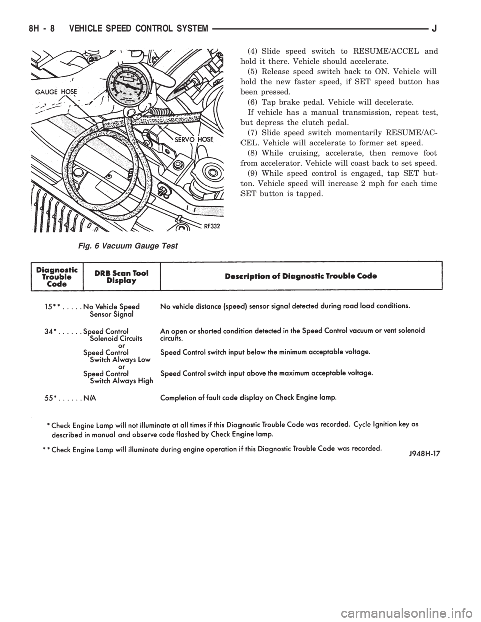
Fig. 6 Vacuum Gauge Test
8H - 8 VEHICLE SPEED CONTROL SYSTEMJ
Page 488 of 1784
CHIME/BUZZER WARNING SYSTEMS
CONTENTS
page page
GENERAL.............................. 1
IGNITION KEY WARNING SWITCH REPLACEMENT.4OPERATION/DIAGNOSIS.................. 1
GENERAL
The buzzer or optional chime module is mounted on
the left side of the fuse block (above and to the left of
the brake/clutch pedal). The buzzer or chime sounds
an audible warning tone in any of the following con-
ditions:
²Vehicle lights are ON when the ignition has been
switched OFF and the key is removed and then the
driver's door is opened (except YJ).²The key is in the ignition and the driver's door is
open (On some vehicles, the buzzer will not sound if
the ignition switch is in the ON position).
²The ignition is switched ON and the driver's seat
belt is not buckled. Buzzer will quit after 4 to 8 sec-
onds. Besides the buzzer, a seat belt indicator lamp
turns on as a reminder to fasten seat belt.
OPERATION/DIAGNOSIS
OPERATION
Battery voltage for module operation is supplied to
two pins. Voltage is always present at pin 7. Pin 1
receives voltage when the ignition switch is in the
ON or START position.
SEAT BELT WARNING
The seat belt warning system uses both visual and
audible signals. These consist of a buzzer that is part
of a combined seat belt and key warning buzzer and
a red light on the instrument panel.
The system will always illuminate the seat belt
warning lamp for four to eight seconds when the ig-
nition switch is turned to the ON position. Also, only
if the driver does not fasten his seat belt, the buzzer
will sound during the same time interval. Passenger
belts are not connected to the system.
A timed buzzer-relay is used to operate the system
for the time period. It has a time delay mechanism
and buzzer assembly. Only the driver's seat belt
buckle has a switch that is connected to the system.
KEY-IN-IGNITION WARNING
To sound the key-in-ignition warning, the following
must occur:
²the ignition key warning switch must be closed
²the driver's door jamb switch must be closed.
These conditions ground pin 6 of the module. These
switches are closed when the key is in the ignition
and the driver's door is open.On some vehicles the chime/buzzer will not
sound if the door is open and the key is in the
ON position.
LIGHTS-ON WARNING (EXCEPT YJ)
To sound the lights-on warning, the following must
occur:
²the headlamp switch must be closed
²the driver's door jamb switch must be closed.
These conditions ground pin 6 of the module. These
switches are closed when the headlamp switch is ON
and the driver's door is open.
DIAGNOSIS
If the buzzer/chime unit does not operate as de-
scribed, check the two fuses for pins 1 and 7 (Figs. 1
and 2) and replace as required. If the fuses are not
defective, perform the following tests to determine if
the problem is in the module or in the wiring. Using
a flat head screwdriver, release the locking plastic
clip while carefully pulling out the module. Plug in a
known good module and check its operation. If the
problem is not corrected by replacing the module, re-
move the module and continue as follows:
VOLTAGE TESTS
Ignition in ON position, measure between the
following pins and vehicle ground.
²Measure voltage at buzzer/chime module connector
pin 1. Meter should read battery voltage. If not, re-
pair open to ignition switch.
Turn ignition OFF and remove the key from the ig-
nition.
JCHIME/BUZZER WARNING SYSTEMS 8U - 1