1994 JEEP CHEROKEE door lock
[x] Cancel search: door lockPage 646 of 1784
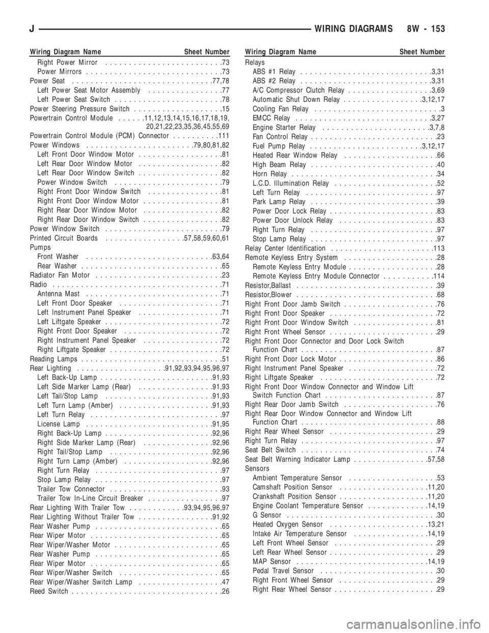
Wiring Diagram Name Sheet Number
Right Power Mirror.........................73
Power Mirrors.............................73
Power Seat..............................77,78
Left Power Seat Motor Assembly................77
Left Power Seat Switch.......................78
Power Steering Pressure Switch...................15
Powertrain Control Module......11,12,13,14,15,16,17,18,19,
20,21,22,23,35,36,45,55,69
Powertrain Control Module (PCM) Connector..........111
Power Windows.......................79,80,81,82
Left Front Door Window Motor..................81
Left Rear Door Window Motor..................82
Left Rear Door Window Switch..................82
Power Window Switch.......................79
Right Front Door Window Switch................81
Right Front Door Window Motor.................81
Right Rear Door Window Motor.................82
Right Rear Door Window Switch.................82
Power Window Switch.........................79
Printed Circuit Boards.................57,58,59,60,61
Pumps
Front Washer...........................63,64
Rear Washer..............................65
Radiator Fan Motor...........................23
Radio....................................71
Antenna Mast.............................71
Left Front Door Speaker......................71
Left Instrument Panel Speaker..................71
Left Liftgate Speaker.........................72
Right Front Door Speaker.....................72
Right Instrument Panel Speaker.................72
Right Liftgate Speaker........................72
Reading Lamps..............................51
Rear Lighting...................91,92,93,94,95,96,97
Left Back-Up Lamp........................91,93
Left Side Marker Lamp (Rear)................91,93
Left Tail/Stop Lamp.......................91,93
Left Turn Lamp (Amber)....................91,93
Left Turn Relay............................97
License Lamp...........................91,95
Right Back-Up Lamp.......................92,96
Right Side Marker Lamp (Rear)...............92,96
Right Tail/Stop Lamp......................92,96
Right Turn Lamp (Amber)...................92,96
Right Turn Relay...........................97
Stop Lamp Relay...........................97
Trailer Tow Connector........................93
Trailer Tow In-Line Circuit Breaker................97
Rear Lighting With Trailer Tow............93,94,95,96,97
Rear Lighting Without Trailer Tow................91,92
Rear Washer Pump...........................65
Rear Wiper Motor............................65
Rear Wiper/Washer Motor.......................65
Rear Washer Pump...........................65
Rear Wiper Motor............................65
Rear Wiper/Washer Switch......................65
Rear Wiper/Washer Switch Lamp..................47
Reed Switch................................26Wiring Diagram Name Sheet Number
Relays
ABS #1 Relay............................3,31
ABS #2 Relay............................3,31
A/C Compressor Clutch Relay..................3,69
Automatic Shut Down Relay.................3,12,17
Cooling Fan Relay...........................3
EMCC Relay.............................3,27
Engine Starter Relay.......................3,7,8
Fan Control Relay...........................23
Fuel Pump Relay........................3,12,17
Heated Rear Window Relay....................66
High Beam Relay...........................40
Horn Relay...............................34
L.C.D. Illumination Relay......................52
Left Turn Relay............................97
Park Lamp Relay...........................39
Power Door Lock Relay.......................83
Power Door Unlock Relay.....................83
Right Turn Relay...........................97
Stop Lamp Relay...........................97
Relay Center Identification......................113
Remote Keyless Entry System....................28
Remote Keyless Entry Module...................28
Remote Keyless Entry Module Connector...........114
Resistor,Ballast..............................39
Resistor,Blower..............................68
Right Front Door Jamb Switch....................76
Right Front Door Speaker.......................72
Right Front Door Window Switch..................81
Right Front Wheel Sensor.......................29
Right Front Door Connector and Door Lock Switch
Function Chart.............................87
Right Front Door Lock Motor.....................86
Right Instrument Panel Speaker...................72
Right Liftgate Speaker.........................72
Right Front Door Window Connector and Window Lift
Switch Function Chart........................87
Right Rear Door Jamb Switch....................76
Right Rear Door Window Connector and Window Lift
Function Chart.............................88
Right Rear Wheel Sensor.......................29
Right Turn Relay.............................97
Seat Belt Switch.............................74
Seat Belt Warning Indicator Lamp................57,58
Sensors
Ambient Temperature Sensor...................53
Camshaft Position Sensor...................11,20
Crankshaft Position Sensor...................11,20
Engine Coolant Temperature Sensor.............14,19
G Sensor................................30
Heated Oxygen Sensor.....................13,21
Intake Air Temperature Sensor................14,19
Left Front Wheel Sensor......................29
Left Rear Wheel Sensor.......................29
MAP Sensor............................14,19
Pedal Travel Sensor.........................30
Right Front Wheel Sensor.....................29
Right Rear Wheel Sensor......................29
JWIRING DIAGRAMS 8W - 153
Page 647 of 1784
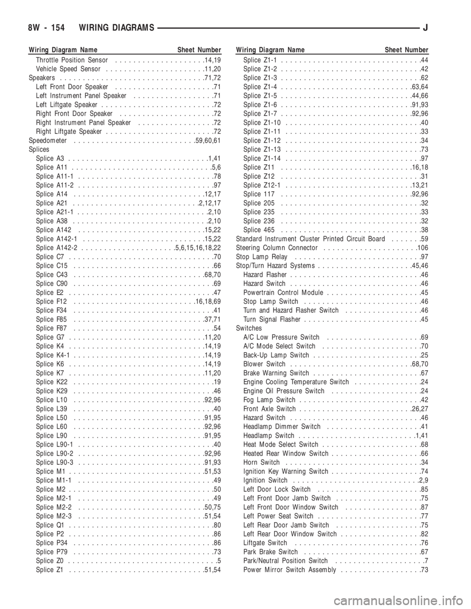
Wiring Diagram Name Sheet Number
Throttle Position Sensor....................14,19
Vehicle Speed Sensor......................11,20
Speakers................................71,72
Left Front Door Speaker......................71
Left Instrument Panel Speaker..................71
Left Liftgate Speaker.........................72
Right Front Door Speaker.....................72
Right Instrument Panel Speaker.................72
Right Liftgate Speaker........................72
Speedometer...........................59,60,61
Splices
Splice A3...............................1,41
Splice A11...............................5,6
Splice A11-1..............................78
Splice A11-2..............................97
Splice A14.............................12,17
Splice A21............................2,12,17
Splice A21-1.............................2,10
Splice A38..............................2,10
Splice A142............................15,22
Splice A142-1...........................15,22
Splice A142-2.....................5,6,15,16,18,22
Splice C7................................70
Splice C15...............................66
Splice C43.............................68,70
Splice C90...............................69
Splice E2................................47
Splice F12...........................16,18,69
Splice F34...............................41
Splice F85.............................37,71
Splice F87...............................54
Splice G7..............................11,20
Splice K4..............................14,19
Splice K4-1.............................14,19
Splice K6..............................14,19
Splice K7..............................11,20
Splice K22...............................19
Splice K29...............................46
Splice L10.............................92,96
Splice L39...............................40
Splice L50.............................91,95
Splice L60.............................92,96
Splice L90.............................91,95
Splice L90-1..............................40
Splice L90-2............................92,96
Splice L90-3............................91,93
Splice M1..............................51,53
Splice M1-1..............................49
Splice M2................................50
Splice M2-1..............................49
Splice M2-2............................50,75
Splice M2-3............................51,54
Splice Q1................................80
Splice P2................................86
Splice P34...............................86
Splice P79...............................73
Splice Z0.................................5
Splice Z1..............................51,54Wiring Diagram Name Sheet Number
Splice Z1-1...............................44
Splice Z1-2...............................42
Splice Z1-3...............................62
Splice Z1-4.............................63,64
Splice Z1-5.............................44,66
Splice Z1-6.............................91,93
Splice Z1-7.............................92,96
Splice Z1-10..............................40
Splice Z1-11..............................33
Splice Z1-12..............................34
Splice Z1-13..............................73
Splice Z1-14..............................97
Splice Z11.............................16,18
Splice Z12...............................31
Splice Z12-1............................13,21
Splice 117.............................92,96
Splice 205...............................32
Splice 235...............................33
Splice 236...............................32
Splice 465...............................38
Standard Instrument Cluster Printed Circuit Board.......59
Steering Column Connector.....................106
Stop Lamp Relay............................97
Stop/Turn Hazard Systems.....................45,46
Hazard Flasher.............................46
Hazard Switch.............................46
Powertrain Control Module.....................45
Stop Lamp Switch..........................46
Turn and Hazard Flasher Switch.................46
Turn Signal Flasher..........................45
Switches
A/C Low Pressure Switch.....................69
A/C Mode Select Switch......................70
Back-Up Lamp Switch........................25
Blower Switch...........................68,70
Brake Warning Switch........................67
Engine Cooling Temperature Switch...............24
Engine Oil Pressure Switch....................24
Fog Lamp Switch...........................42
Front Axle Switch.........................26,27
Hazard Switch.............................46
Headlamp Dimmer Switch.....................41
Headlamp Switch..........................1,41
Heat Mode Select Switch......................68
Heated Rear Window Switch....................66
Horn Switch..............................34
Ignition Key Warning Switch....................74
Ignition Switch............................2,9
Left Door Lock Switch.......................85
Left Front Door Jamb Switch...................75
Left Front Door Window Switch.................87
Left Power Seat Switch.......................77
Left Rear Door Jamb Switch...................75
Left Rear Door Window Switch..................82
Liftgate Switch............................76
Park Brake Switch..........................67
Park/Neutral Position Switch....................7
Power Mirror Switch Assembly..................73
8W - 154 WIRING DIAGRAMSJ
Page 648 of 1784
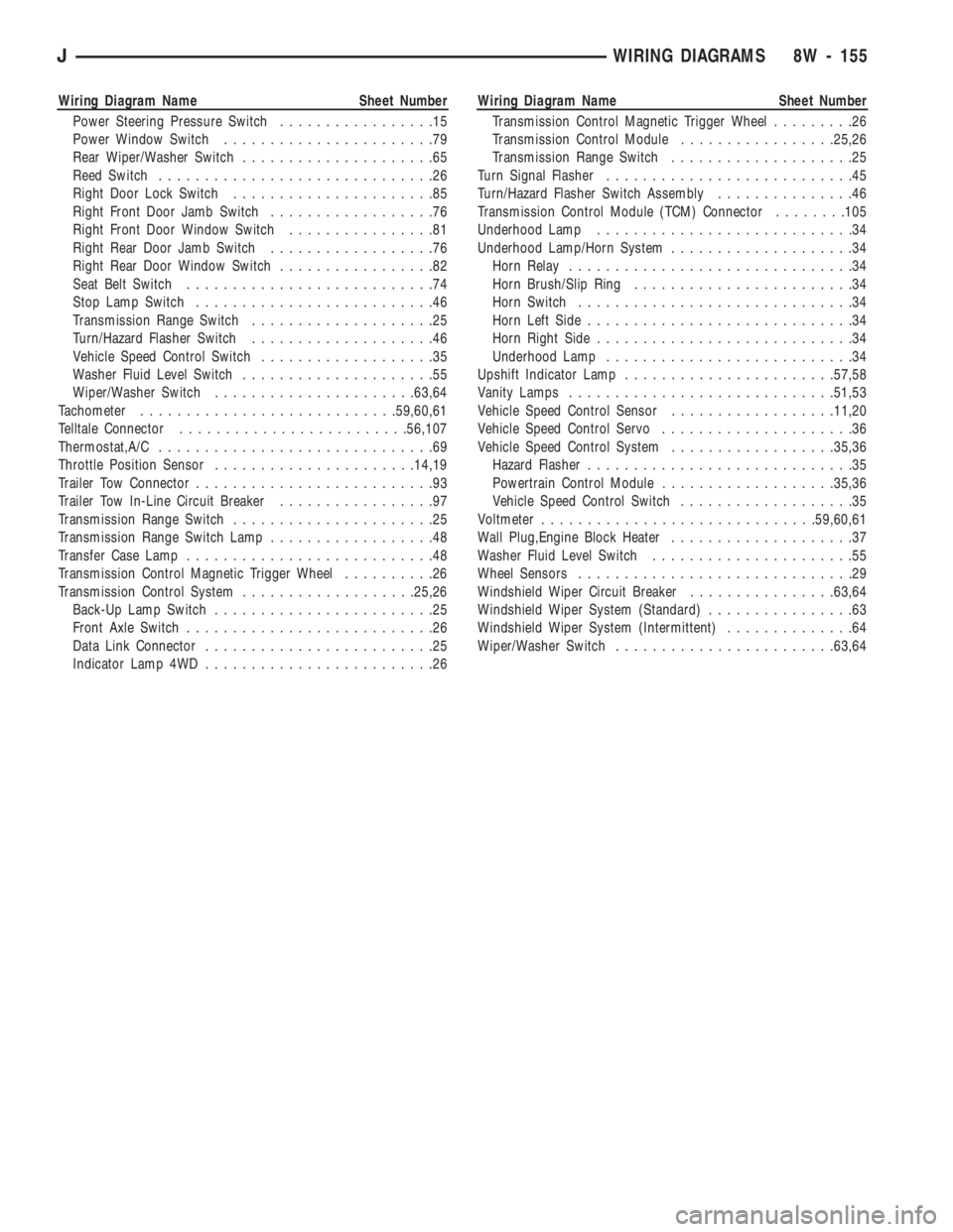
Wiring Diagram Name Sheet Number
Power Steering Pressure Switch.................15
Power Window Switch.......................79
Rear Wiper/Washer Switch.....................65
Reed Switch..............................26
Right Door Lock Switch......................85
Right Front Door Jamb Switch..................76
Right Front Door Window Switch................81
Right Rear Door Jamb Switch..................76
Right Rear Door Window Switch.................82
Seat Belt Switch...........................74
Stop Lamp Switch..........................46
Transmission Range Switch....................25
Turn/Hazard Flasher Switch....................46
Vehicle Speed Control Switch...................35
Washer Fluid Level Switch.....................55
Wiper/Washer Switch......................63,64
Tachometer............................59,60,61
Telltale Connector.........................56,107
Thermostat,A/C..............................69
Throttle Position Sensor......................14,19
Trailer Tow Connector..........................93
Trailer Tow In-Line Circuit Breaker.................97
Transmission Range Switch......................25
Transmission Range Switch Lamp..................48
Transfer Case Lamp...........................48
Transmission Control Magnetic Trigger Wheel..........26
Transmission Control System...................25,26
Back-Up Lamp Switch........................25
Front Axle Switch...........................26
Data Link Connector.........................25
Indicator Lamp 4WD.........................26Wiring Diagram Name Sheet Number
Transmission Control Magnetic Trigger Wheel.........26
Transmission Control Module.................25,26
Transmission Range Switch....................25
Turn Signal Flasher...........................45
Turn/Hazard Flasher Switch Assembly...............46
Transmission Control Module (TCM) Connector........105
Underhood Lamp............................34
Underhood Lamp/Horn System....................34
Horn Relay...............................34
Horn Brush/Slip Ring........................34
Horn Switch..............................34
Horn Left Side.............................34
Horn Right Side............................34
Underhood Lamp...........................34
Upshift Indicator Lamp.......................57,58
Vanity Lamps.............................51,53
Vehicle Speed Control Sensor..................11,20
Vehicle Speed Control Servo.....................36
Vehicle Speed Control System..................35,36
Hazard Flasher.............................35
Powertrain Control Module...................35,36
Vehicle Speed Control Switch...................35
Voltmeter..............................59,60,61
Wall Plug,Engine Block Heater....................37
Washer Fluid Level Switch......................55
Wheel Sensors..............................29
Windshield Wiper Circuit Breaker................63,64
Windshield Wiper System (Standard)................63
Windshield Wiper System (Intermittent)..............64
Wiper/Washer Switch........................63,64
JWIRING DIAGRAMS 8W - 155
Page 764 of 1784
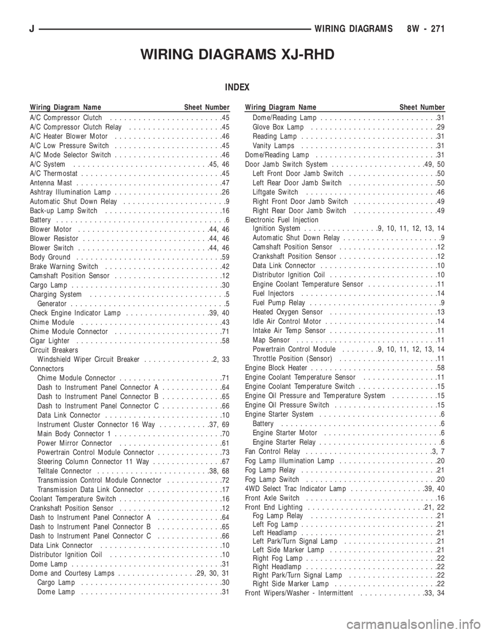
WIRING DIAGRAMS XJ-RHD
INDEX
Wiring Diagram Name Sheet Number
A/C Compressor Clutch........................45
A/C Compressor Clutch Relay....................45
A/C Heater Blower Motor.......................46
A/C Low Pressure Switch.......................45
A/C Mode Selector Switch.......................46
A/C System.............................45, 46
A/C Thermostat..............................45
Antenna Mast...............................47
Ashtray Illumination Lamp.......................26
Automatic Shut Down Relay......................9
Back-up Lamp Switch.........................16
Battery....................................6
Blower Motor............................44, 46
Blower Resistor...........................44, 46
Blower Switch............................44, 46
Body Ground...............................59
Brake Warning Switch.........................42
Camshaft Position Sensor.......................12
Cargo Lamp................................30
Charging System.............................5
Generator.................................5
Check Engine Indicator Lamp..................39, 40
Chime Module..............................43
Chime Module Connector.......................71
Cigar Lighter...............................58
Circuit Breakers
Windshield Wiper Circuit Breaker...............2,33
Connectors
Chime Module Connector......................71
Dash to Instrument Panel Connector A.............64
Dash to Instrument Panel Connector B.............65
Dash to Instrument Panel Connector C.............66
Data Link Connector.........................10
Instrument Cluster Connector 16 Way...........37, 69
Main Body Connector 1.......................70
Power Mirror Connector......................61
Powertrain Control Module Connector..............73
Steering Column Connector 11 Way...............67
Telltale Connector........................38, 68
Transmission Control Module Connector............72
Transmission Data Link Connector................17
Coolant Temperature Switch......................16
Crankshaft Position Sensor......................12
Dash to Instrument Panel Connector A..............64
Dash to Instrument Panel Connector B..............65
Dash to Instrument Panel Connector C..............66
Data Link Connector..........................10
Distributor Ignition Coil........................10
Dome Lamp................................31
Dome and Courtesy Lamps.................29, 30, 31
Cargo Lamp..............................30
Dome Lamp..............................31Wiring Diagram Name Sheet Number
Dome/Reading Lamp.........................31
Glove Box Lamp...........................29
Reading Lamp.............................31
Vanity Lamps.............................31
Dome/Reading Lamp..........................31
Door Jamb Switch System....................49, 50
Left Front Door Jamb Switch...................50
Left Rear Door Jamb Switch...................50
Liftgate Switch............................46
Right Front Door Jamb Switch..................49
Right Rear Door Jamb Switch..................49
Electronic Fuel Injection
Ignition System................9,10,11,12,13,14
Automatic Shut Down Relay.....................9
Camshaft Position Sensor.....................12
Crankshaft Position Sensor.....................12
Data Link Connector.........................10
Distributor Ignition Coil.......................10
Engine Coolant Temperature Sensor...............11
Fuel Injectors.............................14
Fuel Pump Relay............................9
Heated Oxygen Sensor.......................13
Idle Air Control Motor........................14
Intake Air Temp Sensor.......................11
Map Sensor..............................11
Powertrain Control Module........9,10,11,12,13,14
Throttle Position (Sensor).....................11
Engine Block Heater...........................58
Engine Coolant Temperature Sensor................11
Engine Coolant Temperature Switch.................15
Engine Oil Pressure and Temperature System..........15
Engine Oil Pressure Switch......................15
Engine Starter System..........................6
Battery..................................6
Engine Starter Motor.........................6
Engine Starter Relay..........................6
Fan Control Relay...........................3,7
Fog Lamp Illumination Lamp.....................20
Fog Lamp Relay.............................21
Fog Lamp Switch............................20
4WD Select Trac Indicator Lamp................39, 40
Front Axle Switch............................16
Front End Lighting.........................21, 22
Fog Lamp Relay...........................21
Left Fog Lamp.............................21
Left Headlamp.............................21
Left Park/Turn Signal Lamp....................21
Left Side Marker Lamp.......................21
Right Fog Lamp............................22
Right Headlamp............................22
Right Park/Turn Signal Lamp...................22
Right Side Marker Lamp......................22
Front Wipers/Washer - Intermittent..............33, 34
JWIRING DIAGRAMS 8W - 271
Page 1229 of 1784
OVERHAUL SERVICE INFORMATION
Inspect the transmission bushings during overhaul.
Bushing condition is important as severely worn, or
scored bushings contribute to low pressures, clutch
slip and accelerated wear of other components.How-
ever, do not replace bushings as a matter of
course. Replace bushings only when they are
actually worn, or scored.
Use recommended tools to replace bushings. The
tools are sized and designed to remove, install and
seat bushings correctly. The bushing replacement
tools are included in Bushing Tool Set C-3887-B. The
tool set is manufactured by Miller Tool Co. and is
available through the dealer tool program.
Pre-sized service bushings are available for replace-
ment purposes. Only the sun gear bushings are not
serviced. Low cost of the sun gear assembly makes it
easier to simply replace the gear and bushings as an
assembly.
Heli-Coil inserts are recommended for repairing
damaged, stripped or worn threads in aluminum
parts. These inserts are available from most automo-
tive jobbers. Stainless steel inserts are preferred.
The use of crocus cloth is permissible where neces-
sary. When used on valves, use care to avoid round-
ing off sharp edges. Sharp edges are vital as they
prevent foreign matter from getting between the
valve and valve bore.
Do not reuse oil seals, gaskets, seal rings, or O-
rings during overhaul. Replace these parts as a mat-
ter of course. Also do not reuse snap rings or E-clips
that are bent or distorted. Replace these parts as
well.
Lubricate transmission parts with Mopar ATF
Plus, Type 7176 transmission fluid during overhaul
and assembly.Use petroleum jelly to hold parts like thrust wash-
ers in place during assembly. Use Ru-Glyde, Door
Eze, or similar products to lubricate piston seals and
O-rings to ease installation. Petroleum jelly can also
be used to prelubricate parts during reassembly if de-
sired.
TRANSMISSION CASE CLEANING AND
INSPECTION
Clean the case in a solvent tank. Flush the case
bores and fluid passages thoroughly with solvent.
Dry the case and all fluid passages with compressed
air. Be sure all solvent is removed from the case and
that all fluid passages are clear.
Do not use shop towels or rags to dry the case
(or any other transmission component) unless
they are made from lint-free materials. Lint will
readily adhere to case surfaces and transmission
components and will circulate throughout the
transmission after assembly. A sufficient quan-
tity of lint can block fluid passages and interfere
with valve body operation.
Inspect the case for cracks, porous spots, worn
bores, or damaged threads. Damaged threads can be
repaired with Helicoil thread inserts. However, the
case will have to be replaced if it exhibits any type of
damage or wear.
Lubricate the front band adjusting screw threads
with petroleum jelly and thread the screw part-way
into the case. Be sure the screw turns freely.
Remount the case in a repair stand after cleaning
and inspection.
OVERRUNNING CLUTCHÐLOW-REVERSE
DRUMÐREAR SUPPORT OVERHAUL
DISASSEMBLING OVERRUNNING CLUTCH/
LOW-REVERSE DRUM
If the clutch assembly came out with the low-re-
verse drum, thread two clutch cam bolts into the
cam. Then lift the cam out of the drum with the bolts
(Fig. 30). Rotate the cam back and forth to ease re-
moval if necessary. Remove the clutch roller and
spring assembly from the race afterward.
CLEANING AND INSPECTION
Clean the overrunning clutch assembly, clutch
cam, low-reverse drum and rear support in solvent.
Dry them with compressed air after cleaning.
Inspect condition of each clutch part after cleaning.
Replace the overrunning clutch roller and spring as-
sembly if any rollers or springs are worn or dam-
aged, or if the roller cage is distorted, or damaged.
Replace the cam if worn, cracked or damaged.
Replace the low-reverse drum if the clutch race,
roller surface or inside diameter is scored, worn or
damaged.Do not remove the clutch race from the
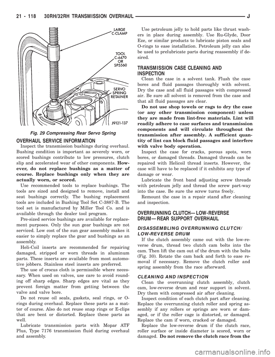
Fig. 29 Compressing Rear Servo Spring
21 - 118 30RH/32RH TRANSMISSION OVERHAULJ
Page 1241 of 1784
seal ring is teflon with chamfered ends. The rear
ring is metal with interlocking ends.
Check the input shaft for wear, or damage. Replace
the shaft if worn, scored or damaged in any way.
ASSEMBLING REAR CLUTCH
(1) Soak clutch discs in transmission fluid while
assembling other clutch parts.
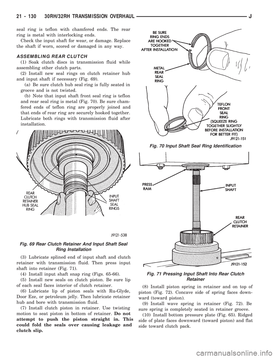
(2) Install new seal rings on clutch retainer hub
and input shaft if necessary (Fig. 69).
(a) Be sure clutch hub seal ring is fully seated in
groove and is not twisted.
(b) Note that input shaft front seal ring is teflon
and rear seal ring is metal (Fig. 70). Be sure cham-
fered ends of teflon ring are properly joined and
that ends of rear ring are securely hooked together.
Lubricate both rings with transmission fluid after
installation.
(3) Lubricate splined end of input shaft and clutch
retainer with transmission fluid. Then press input
shaft into retainer (Fig. 71).
(4) Install input shaft snap ring (Figs. 65-66).
(5) Install new seals on clutch piston. Be sure lip
of each seal faces interior of clutch retainer.
(6) Lubricate lip of piston seals with Ru-Glyde,
Door Eze, or petroleum jelly. Then lubricate retainer
hub and bore with transmission fluid.
(7) Install clutch piston in retainer. Use twisting
motion to seat piston in bottom of retainer.Do not
attempt to push the piston straight in. This
could fold the seals over causing leakage and
clutch slip.(8) Install piston spring in retainer and on top of
piston (Fig. 72). Concave side of spring faces down-
ward (toward piston).
(9) Install wave spring in retainer (Fig. 72). Be
sure spring is completely seated in retainer groove.
(10) Install bottom pressure plate (Fig. 65). Ridged
side of plate faces downward (toward piston) and flat
side toward clutch pack.
Fig. 69 Rear Clutch Retainer And Input Shaft Seal
Ring Installation
Fig. 70 Input Shaft Seal Ring Identification
Fig. 71 Pressing Input Shaft Into Rear Clutch
Retainer
21 - 130 30RH/32RH TRANSMISSION OVERHAULJ
Page 1257 of 1784
rect sequence. The correct sequence is line pressure
adjustment first and throttle pressure adjustment
last.
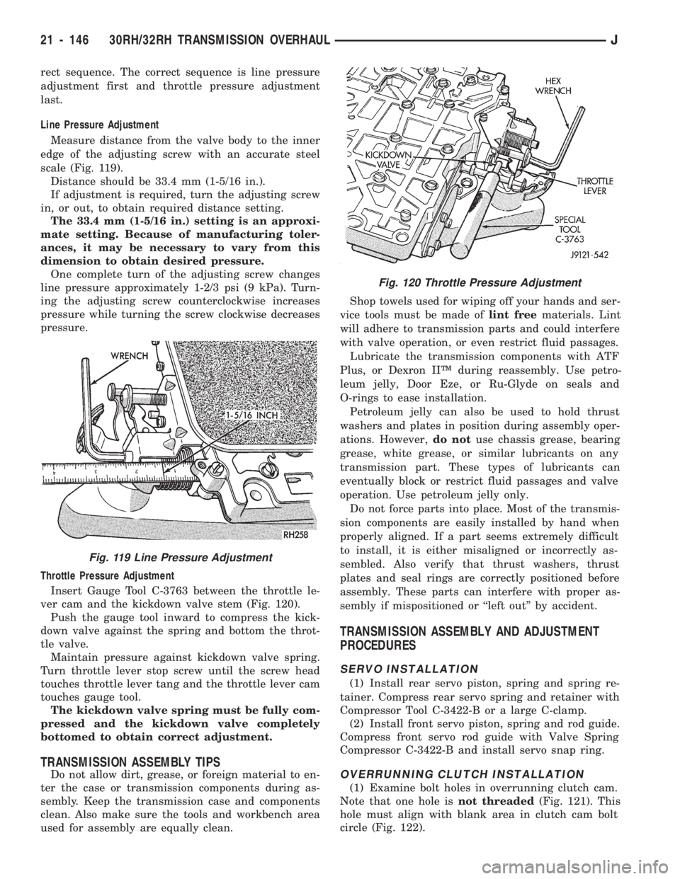
Line Pressure Adjustment
Measure distance from the valve body to the inner
edge of the adjusting screw with an accurate steel
scale (Fig. 119).
Distance should be 33.4 mm (1-5/16 in.).
If adjustment is required, turn the adjusting screw
in, or out, to obtain required distance setting.
The 33.4 mm (1-5/16 in.) setting is an approxi-
mate setting. Because of manufacturing toler-
ances, it may be necessary to vary from this
dimension to obtain desired pressure.
One complete turn of the adjusting screw changes
line pressure approximately 1-2/3 psi (9 kPa). Turn-
ing the adjusting screw counterclockwise increases
pressure while turning the screw clockwise decreases
pressure.
Throttle Pressure Adjustment
Insert Gauge Tool C-3763 between the throttle le-
ver cam and the kickdown valve stem (Fig. 120).
Push the gauge tool inward to compress the kick-
down valve against the spring and bottom the throt-
tle valve.
Maintain pressure against kickdown valve spring.
Turn throttle lever stop screw until the screw head
touches throttle lever tang and the throttle lever cam
touches gauge tool.
The kickdown valve spring must be fully com-
pressed and the kickdown valve completely
bottomed to obtain correct adjustment.
TRANSMISSION ASSEMBLY TIPS
Do not allow dirt, grease, or foreign material to en-
ter the case or transmission components during as-
sembly. Keep the transmission case and components
clean. Also make sure the tools and workbench area
used for assembly are equally clean.Shop towels used for wiping off your hands and ser-
vice tools must be made oflint freematerials. Lint
will adhere to transmission parts and could interfere
with valve operation, or even restrict fluid passages.
Lubricate the transmission components with ATF
Plus, or Dexron IIŸ during reassembly. Use petro-
leum jelly, Door Eze, or Ru-Glyde on seals and
O-rings to ease installation.
Petroleum jelly can also be used to hold thrust
washers and plates in position during assembly oper-
ations. However,do notuse chassis grease, bearing
grease, white grease, or similar lubricants on any
transmission part. These types of lubricants can
eventually block or restrict fluid passages and valve
operation. Use petroleum jelly only.
Do not force parts into place. Most of the transmis-
sion components are easily installed by hand when
properly aligned. If a part seems extremely difficult
to install, it is either misaligned or incorrectly as-
sembled. Also verify that thrust washers, thrust
plates and seal rings are correctly positioned before
assembly. These parts can interfere with proper as-
sembly if mispositioned or ``left out'' by accident.
TRANSMISSION ASSEMBLY AND ADJUSTMENT
PROCEDURES
SERVO INSTALLATION
(1) Install rear servo piston, spring and spring re-
tainer. Compress rear servo spring and retainer with
Compressor Tool C-3422-B or a large C-clamp.
(2) Install front servo piston, spring and rod guide.
Compress front servo rod guide with Valve Spring
Compressor C-3422-B and install servo snap ring.
OVERRUNNING CLUTCH INSTALLATION
(1) Examine bolt holes in overrunning clutch cam.
Note that one hole isnot threaded(Fig. 121). This
hole must align with blank area in clutch cam bolt
circle (Fig. 122).
Fig. 120 Throttle Pressure Adjustment
Fig. 119 Line Pressure Adjustment
21 - 146 30RH/32RH TRANSMISSION OVERHAULJ
Page 1457 of 1784
KEY LOCK CYLINDERS
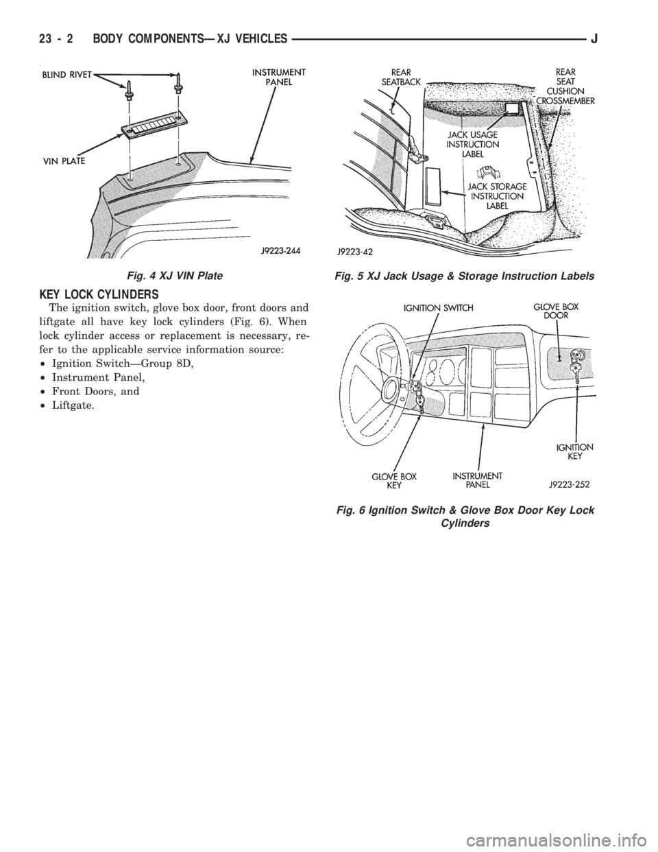
The ignition switch, glove box door, front doors and
liftgate all have key lock cylinders (Fig. 6). When
lock cylinder access or replacement is necessary, re-
fer to the applicable service information source:
²Ignition SwitchÐGroup 8D,
²Instrument Panel,
²Front Doors, and
²Liftgate.
Fig. 4 XJ VIN PlateFig. 5 XJ Jack Usage & Storage Instruction Labels
Fig. 6 Ignition Switch & Glove Box Door Key Lock
Cylinders
23 - 2 BODY COMPONENTSÐXJ VEHICLESJ