1994 JEEP CHEROKEE wheel torque
[x] Cancel search: wheel torquePage 156 of 1784

Brake drag also has a direct effect on fuel economy.
If undetected, minor brake drag can be misdiagnosed
as an engine or transmission/torque converter prob-
lem.
Minor drag will usually cause slight surface char-
ring of the lining. It can also generate hard spots in
rotors and drums from the overheat/cool down pro-
cess. In most cases, the rotors, drums, wheels and
tires are quite warm to the touch after the vehicle is
stopped.
Severe drag can char the brake lining all the way
through. It can also distort and score rotors and
drums to the point of replacement. The wheels, tires
and brake components will be extremely hot. In se-
vere cases, the lining may generate smoke as it chars
from overheating.
An additional cause of drag involves the use of in-
correct length caliper mounting bolts. Bolts that are
too long can cause a partial apply condition. The cor-
rect caliper bolts have a shank length of 67 mm
(2.637 in.), plus or minus 0.6 mm (0.0236 in.). Refer
to the Disc Brake service section for more detail on
caliper bolt dimensions and identification.
Some common causes of brake drag are:
²loose or damaged wheel bearing
²seized or sticking caliper or wheel cylinder piston
²caliper binding on bushings or slide surfaces
²wrong length caliper mounting bolts (too long)
²loose caliper mounting bracket
²distorted brake drum or shoes
²rear brakeshoes binding on worn/damaged support
plates
²severely rusted/corroded components
²misassembled components.
If brake drag occurs at all wheels, the problem may
be related to a blocked master cylinder compensator
port or faulty power booster (binds-does not release).
The brakelight switch can also be a cause of drag.
An improperly mounted or adjusted brakelight
switch can prevent full brake pedal return. The re-
sult will be the same as if the master cylinder com-
pensator ports are blocked. The brakes would be
partially applied causing drag.
BRAKE FADE
Brake fade is a product of overheating caused by
brake drag. However, overheating and subsequent
fade can also be caused by riding the brake pedal,
making repeated high deceleration stops in a short
time span, or constant braking on steep roads. Refer
to the Brake Drag information in this section for
causes.
PEDAL PULSATION
Pedal pulsation is caused by components that are
loose, or beyond tolerance limits.
Disc brake rotors with excessive lateral runout or
thickness variation, or out of round brake drums arethe primary causes of pulsation. Other causes are
loose wheel bearings or calipers and worn, damaged
tires.
PULL
A front pull condition could be the result of:
²contaminated lining in one caliper
²seized caliper piston
²binding caliper
²wrong caliper mounting bolts (too long)
²loose caliper
²loose or corroded mounting bolts
²improper brakeshoes
²damaged rotor
²incorrect wheel bearing adjustment (at one wheel)
A worn, damaged wheel bearing or suspension
component are further causes of pull. A damaged
front tire (bruised, ply separation) can also cause
pull. Wrong caliper bolts (too long) will cause a par-
tial apply condition and pull if only one caliper is in-
volved.
A common and frequently misdiagnosed pull condi-
tion is where direction of pull changes after a few
stops. The cause is a combination of brake drag fol-
lowed by fade at the dragging brake unit.
As the dragging brake overheats, efficiency is so
reduced that fade occurs. If the opposite brake unit is
still functioning normally, its braking effect is mag-
nified. This causes pull to switch direction in favor of
the brake unit that is functioning normally.
When diagnosing a change in pull condition, re-
member that pull will return to the original direction
if the dragging brake unit is allowed to cool down
(and is not seriously damaged).
REAR BRAKE GRAB
Rear grab (or pull) is usually caused by contami-
nated lining, bent or binding shoes and support
plates, or improperly assembled components. This is
particularly true when only one rear wheel is in-
volved. However, when both rear wheels are affected,
the master cylinder or proportioning valve could be
at fault.
BRAKES DO NOT HOLD AFTER DRIVING
THROUGH DEEP WATER PUDDLES
This condition is generally caused by water soaked
lining. If the lining is only wet, it can be dried by
driving with the brakes lightly applied for a mile or
two. However, if the lining is both wet and dirty, dis-
assembly and cleaning will be necessary.
BRAKE FLUID CONTAMINATION
There are two basic causes of brake fluid contami-
nation. The first involves allowing dirt, debris, or
other liquid materials to enter the cylinder reservoirs
JBRAKES 5 - 9
Page 174 of 1784

(8) Install and tighten caliper mounting bolts to
10-20 Nzm (7-15 ft. lbs.) torque.
CAUTION: If new caliper bolts are being installed,
or if the original reason for repair was a drag/pull
condition, check caliper bolt length before proceed-
ing. If the bolts have a shank length greater than
67.6 mm (2.66 in.), they will contact the inboard
brakeshoe causing a partial apply condition. Refer
to Figure 14 for required caliper bolt length.
(9) Install wheels. Tighten lug nuts to 102 Nzm (75
ft. lbs.) torque.
(10) Pump brake pedal until caliper pistons and
brakeshoes are seated.
(11) Top off brake fluid level if necessary. Use Mo-
par brake fluid or equivalent meeting SAE J1703
and DOT 3 standards only.
CALIPER REMOVAL
(1) Raise vehicle and remove front wheels.
(2) Remove caliper mounting bolts (Fig. 4).(3) Rotate caliper rearward by hand or with pry
tool (Fig. 5). Then rotate caliper and brakeshoes off
mounting ledges.
(4) Remove caliper hose fitting bolt and disconnect
front brake hose at caliper. Discard fitting bolt wash-
ers. They are not reusable and should be replaced.
(5) Remove caliper from vehicle.
CALIPER DISASSEMBLY
(1) Remove brakeshoes from caliper.
(2) Pad interior of caliper with minimum, 2.54 cm
(1 in.) thickness of shop towels or rags (Fig. 15). Tow-
els are needed to protect caliper piston during re-
moval.
(3) Remove caliper piston withshort burstsof low
pressure compressed air. Direct air through fluid in-
let port and ease piston out of bore (Fig. 16).
Fig. 11 Installing Inboard Brakeshoe
Fig. 12 Installing Outboard Brakeshoe
Fig. 13 Caliper Installation
Fig. 14 Caliper Mounting Bolt Dimensions
JBRAKES 5 - 27
Page 177 of 1784
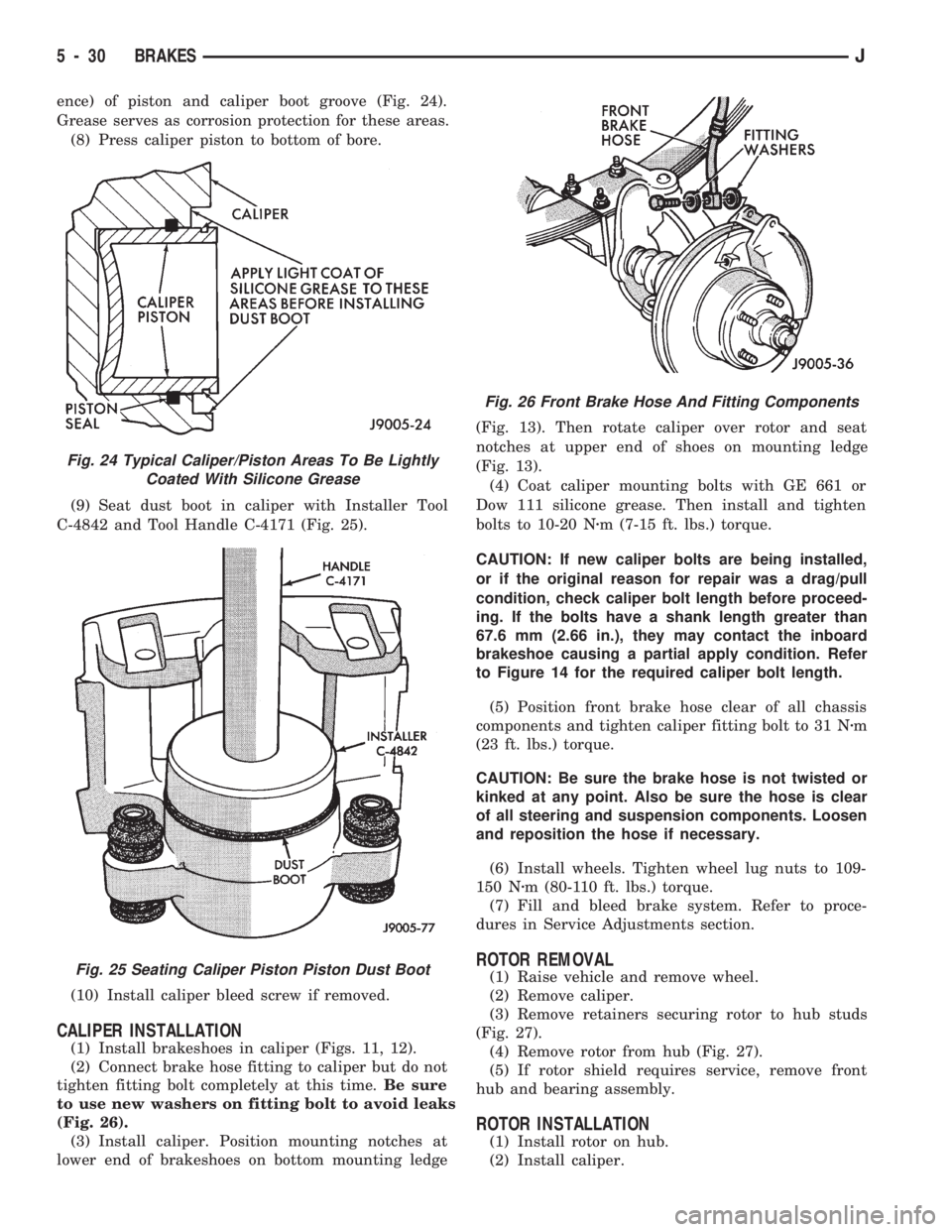
ence) of piston and caliper boot groove (Fig. 24).
Grease serves as corrosion protection for these areas.
(8) Press caliper piston to bottom of bore.
(9) Seat dust boot in caliper with Installer Tool
C-4842 and Tool Handle C-4171 (Fig. 25).
(10) Install caliper bleed screw if removed.
CALIPER INSTALLATION
(1) Install brakeshoes in caliper (Figs. 11, 12).
(2) Connect brake hose fitting to caliper but do not
tighten fitting bolt completely at this time.Be sure
to use new washers on fitting bolt to avoid leaks
(Fig. 26).
(3) Install caliper. Position mounting notches at
lower end of brakeshoes on bottom mounting ledge(Fig. 13). Then rotate caliper over rotor and seat
notches at upper end of shoes on mounting ledge
(Fig. 13).
(4) Coat caliper mounting bolts with GE 661 or
Dow 111 silicone grease. Then install and tighten
bolts to 10-20 Nzm (7-15 ft. lbs.) torque.
CAUTION: If new caliper bolts are being installed,
or if the original reason for repair was a drag/pull
condition, check caliper bolt length before proceed-
ing. If the bolts have a shank length greater than
67.6 mm (2.66 in.), they may contact the inboard
brakeshoe causing a partial apply condition. Refer
to Figure 14 for the required caliper bolt length.
(5) Position front brake hose clear of all chassis
components and tighten caliper fitting bolt to 31 Nzm
(23 ft. lbs.) torque.
CAUTION: Be sure the brake hose is not twisted or
kinked at any point. Also be sure the hose is clear
of all steering and suspension components. Loosen
and reposition the hose if necessary.
(6) Install wheels. Tighten wheel lug nuts to 109-
150 Nzm (80-110 ft. lbs.) torque.
(7) Fill and bleed brake system. Refer to proce-
dures in Service Adjustments section.
ROTOR REMOVAL
(1) Raise vehicle and remove wheel.
(2) Remove caliper.
(3) Remove retainers securing rotor to hub studs
(Fig. 27).
(4) Remove rotor from hub (Fig. 27).
(5) If rotor shield requires service, remove front
hub and bearing assembly.
ROTOR INSTALLATION
(1) Install rotor on hub.
(2) Install caliper.
Fig. 24 Typical Caliper/Piston Areas To Be Lightly
Coated With Silicone Grease
Fig. 25 Seating Caliper Piston Piston Dust Boot
Fig. 26 Front Brake Hose And Fitting Components
5 - 30 BRAKESJ
Page 180 of 1784
cause distortion of the brake rotors and drums.
Impact wrenches are not recommended for tighten-
ing wheel nuts. A torque wrench should be used for
this purpose.
A light coat of LPS Anti-Corrosion spray lube
around the hub face and on the studs will cut down
on rust/corrosion formation.
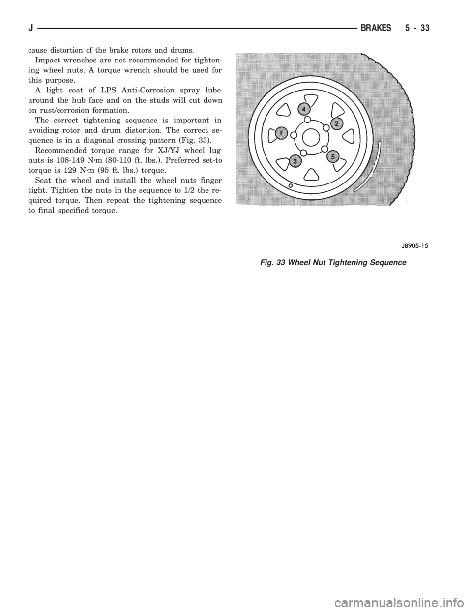
The correct tightening sequence is important in
avoiding rotor and drum distortion. The correct se-
quence is in a diagonal crossing pattern (Fig. 33).
Recommended torque range for XJ/YJ wheel lug
nuts is 108-149 Nzm (80-110 ft. lbs.). Preferred set-to
torque is 129 Nzm (95 ft. lbs.) torque.
Seat the wheel and install the wheel nuts finger
tight. Tighten the nuts in the sequence to 1/2 the re-
quired torque. Then repeat the tightening sequence
to final specified torque.
Fig. 33 Wheel Nut Tightening Sequence
JBRAKES 5 - 33
Page 184 of 1784
(9) Coat cylinder bore, pistons, cups and expander
with brake fluid and reassemble cylinder compo-
nents. Be sure piston cup lips face expander.
WHEEL CYLINDER INSTALLATION
(1) Apply small bead of silicone sealer around cyl-
inder mounting surface of support plate.
(2) Start brakeline in wheel cylinder fitting by
hand.
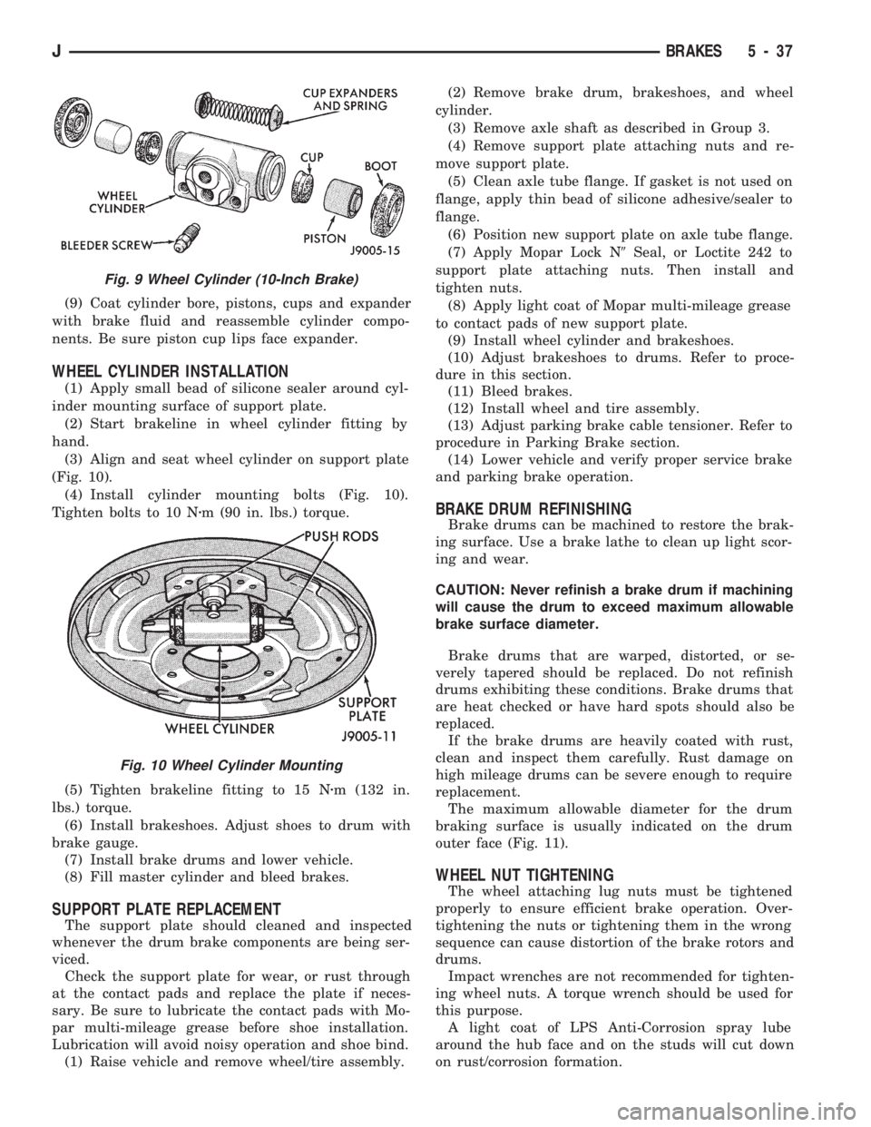
(3) Align and seat wheel cylinder on support plate
(Fig. 10).
(4) Install cylinder mounting bolts (Fig. 10).
Tighten bolts to 10 Nzm (90 in. lbs.) torque.
(5) Tighten brakeline fitting to 15 Nzm (132 in.
lbs.) torque.
(6) Install brakeshoes. Adjust shoes to drum with
brake gauge.
(7) Install brake drums and lower vehicle.
(8) Fill master cylinder and bleed brakes.
SUPPORT PLATE REPLACEMENT
The support plate should cleaned and inspected
whenever the drum brake components are being ser-
viced.
Check the support plate for wear, or rust through
at the contact pads and replace the plate if neces-
sary. Be sure to lubricate the contact pads with Mo-
par multi-mileage grease before shoe installation.
Lubrication will avoid noisy operation and shoe bind.
(1) Raise vehicle and remove wheel/tire assembly.(2) Remove brake drum, brakeshoes, and wheel
cylinder.
(3) Remove axle shaft as described in Group 3.
(4) Remove support plate attaching nuts and re-
move support plate.
(5) Clean axle tube flange. If gasket is not used on
flange, apply thin bead of silicone adhesive/sealer to
flange.
(6) Position new support plate on axle tube flange.
(7) Apply Mopar Lock N9Seal, or Loctite 242 to
support plate attaching nuts. Then install and
tighten nuts.
(8) Apply light coat of Mopar multi-mileage grease
to contact pads of new support plate.
(9) Install wheel cylinder and brakeshoes.
(10) Adjust brakeshoes to drums. Refer to proce-
dure in this section.
(11) Bleed brakes.
(12) Install wheel and tire assembly.
(13) Adjust parking brake cable tensioner. Refer to
procedure in Parking Brake section.
(14) Lower vehicle and verify proper service brake
and parking brake operation.
BRAKE DRUM REFINISHING
Brake drums can be machined to restore the brak-
ing surface. Use a brake lathe to clean up light scor-
ing and wear.
CAUTION: Never refinish a brake drum if machining
will cause the drum to exceed maximum allowable
brake surface diameter.
Brake drums that are warped, distorted, or se-
verely tapered should be replaced. Do not refinish
drums exhibiting these conditions. Brake drums that
are heat checked or have hard spots should also be
replaced.
If the brake drums are heavily coated with rust,
clean and inspect them carefully. Rust damage on
high mileage drums can be severe enough to require
replacement.
The maximum allowable diameter for the drum
braking surface is usually indicated on the drum
outer face (Fig. 11).
WHEEL NUT TIGHTENING
The wheel attaching lug nuts must be tightened
properly to ensure efficient brake operation. Over-
tightening the nuts or tightening them in the wrong
sequence can cause distortion of the brake rotors and
drums.
Impact wrenches are not recommended for tighten-
ing wheel nuts. A torque wrench should be used for
this purpose.
A light coat of LPS Anti-Corrosion spray lube
around the hub face and on the studs will cut down
on rust/corrosion formation.
Fig. 9 Wheel Cylinder (10-Inch Brake)
Fig. 10 Wheel Cylinder Mounting
JBRAKES 5 - 37
Page 185 of 1784
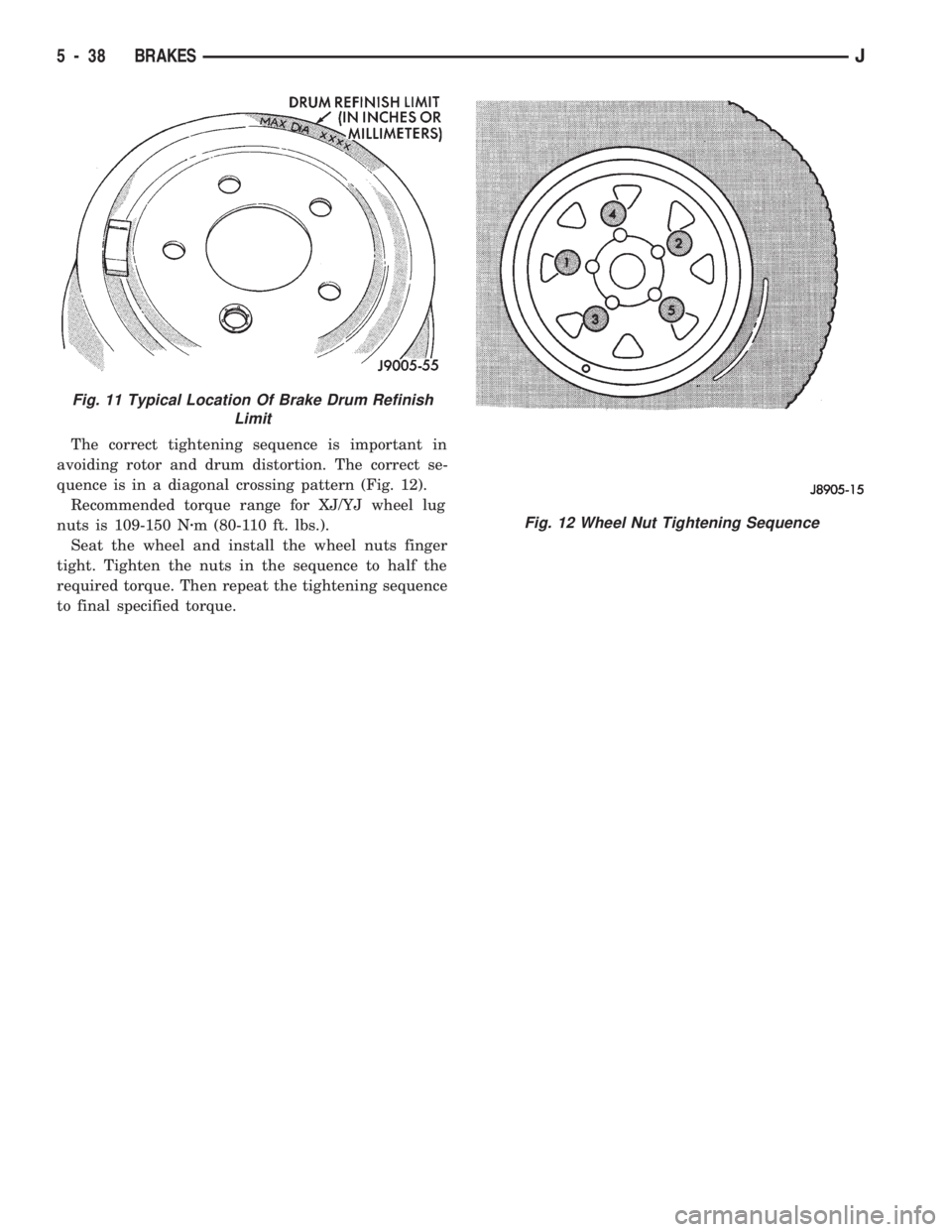
The correct tightening sequence is important in
avoiding rotor and drum distortion. The correct se-
quence is in a diagonal crossing pattern (Fig. 12).
Recommended torque range for XJ/YJ wheel lug
nuts is 109-150 Nzm (80-110 ft. lbs.).
Seat the wheel and install the wheel nuts finger
tight. Tighten the nuts in the sequence to half the
required torque. Then repeat the tightening sequence
to final specified torque.
Fig. 11 Typical Location Of Brake Drum Refinish
Limit
Fig. 12 Wheel Nut Tightening Sequence
5 - 38 BRAKESJ
Page 196 of 1784
Clean the reservoir and caps thoroughly before
checking level or adding fluid. Cap open lines and
hoses during service to prevent dirt entry.
Dirt or foreign material entering the ABS hydrau-
lic system through the reservoir opening will circu-
late within the system. The result will be poor brake
performance and possible component failure. Use
clean, fresh fluid only to top off, or refill the system.
WHEEL SENSOR AIR GAP ADJUSTMENT
Only rear sensor air gap is adjustable. The front
sensors are fixed and cannot be adjusted.
A rear sensor air gap adjustment is only
needed when reinstalling an original sensor. Re-
placement sensors have an air gap spacer at-
tached to the sensor pickup face. The spacer
establishes correct air gap when pressed against
the tone ring during installation. As the tone
ring rotates, it peels the spacer off the sensor to
create the required air gap.
Preferred rear sensor air gap is 1.1 mm (0.043 in.).
Acceptable air gap range is 0.92 to 1.275 mm (0.036
to 0.050 in.).
Front sensor air gap is not adjustable. The front
sensors are fixed in position and cannot be adjusted.
Front sensor air gap can only be checked. Air gap
should be 0.040 to 1.3 mm (0.0157 to 0.051 in.). If
front sensor air gap is incorrect, the sensor is either
loose, or damaged.
FRONT WHEEL SENSOR REMOVAL
(1) Raise vehicle and turn wheel outward for eas-
ier access to sensor.
(2) Remove sensor wire from mounting brackets.
(3) Clean sensor and surrounding area before removal.
(4) Remove bolt attaching sensor to steering
knuckle and remove sensor.
(5) Unseat grommet retaining sensor wire in wheel
house panel.
(6) In engine compartment, disconnect sensor wire con-
nector at harness plug. Then remove sensor and wire.
FRONT WHEEL SENSOR INSTALLATION
(1) Apply Mopar Lock N' Seal or Loctite 242 to
bolt that attaches sensor to steering knuckle. Use
new sensor bolt if original bolt is worn or damaged.
(2) Position sensor on steering knuckle. Seat sen-
sor locating tab in hole in knuckle and install sensor
attaching bolt finger tight.
(3) Tighten sensor bolt to 14 NIm (11 ft. lbs.) torque.
(4) Attach sensor wire to steering knuckle bracket
with grommets on sensor wire.
(5) Route sensor wire forward and behind shock
absorber. Then attach sensor wire to spring seat
bracket with grommets on sensor wire.
(6) Route sensor wire to outer sill bracket. Remove
all twists or kinks from wire.(7) Attach sensor wire to sill bracket with grom-
met. Be sure wire is free of twists and kinks.
(8) Verify sensor wire routing. Wire should loop
forward and above sill bracket. Loose end of wire
should be below sill bracket and towards brake hose.
(9) Seat sensor wire grommet in body panel and
clip wire to brake line at grommet location.
(10) Connect sensor wire to harness in engine com-
partment.
REAR WHEEL SENSOR REMOVAL
(1) On XJ models, if separate connectors are not
used to attach sensor harness to each sensor wire,
proceed as follows:
(a) Raise and fold rear seat forward for access to
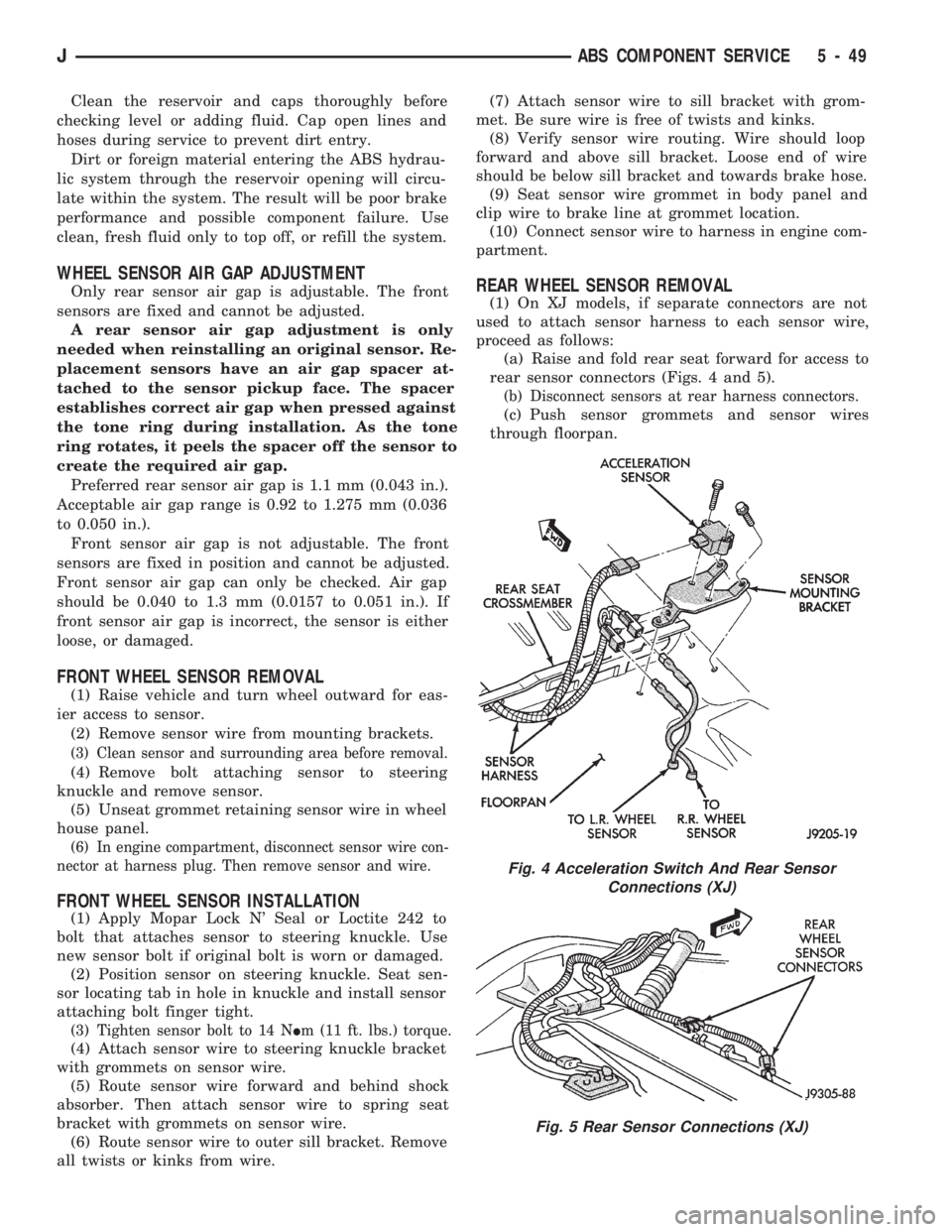
rear sensor connectors (Figs. 4 and 5).
(b) Disconnect sensors at rear harness connectors.
(c) Push sensor grommets and sensor wires
through floorpan.
Fig. 4 Acceleration Switch And Rear Sensor
Connections (XJ)
Fig. 5 Rear Sensor Connections (XJ)
JABS COMPONENT SERVICE 5 - 49
Page 197 of 1784
(2) Raise vehicle.
(3) Disconnect sensor wires at rear axle connectors.
(4) Remove wheel and tire assembly.
(5) Remove brake drum.
(6) Remove clips securing sensor wires to brake
lines or rear axle and rear brake hose.
(7) Unseat sensor support plate grommet.
(8) Remove bolt attaching sensor to bracket and
remove sensor.
REAR WHEEL SENSOR INSTALLATION
(1) Insert sensor wire through support plate hole
and seat sensor grommet in support plate.
(2) Apply Mopar Lock N' Seal or Loctite 242 to
original sensor bolt. Use new bolt if original is worn
or damaged.
(3) Install sensor bolt finger tight only at this
time.
(4) Set sensor air gap as follows:
(a) Iforiginal sensoris being installed, remove
any remaining pieces of cardboard spacer from sen-
sor pickup face. Then adjust air gap to preferred
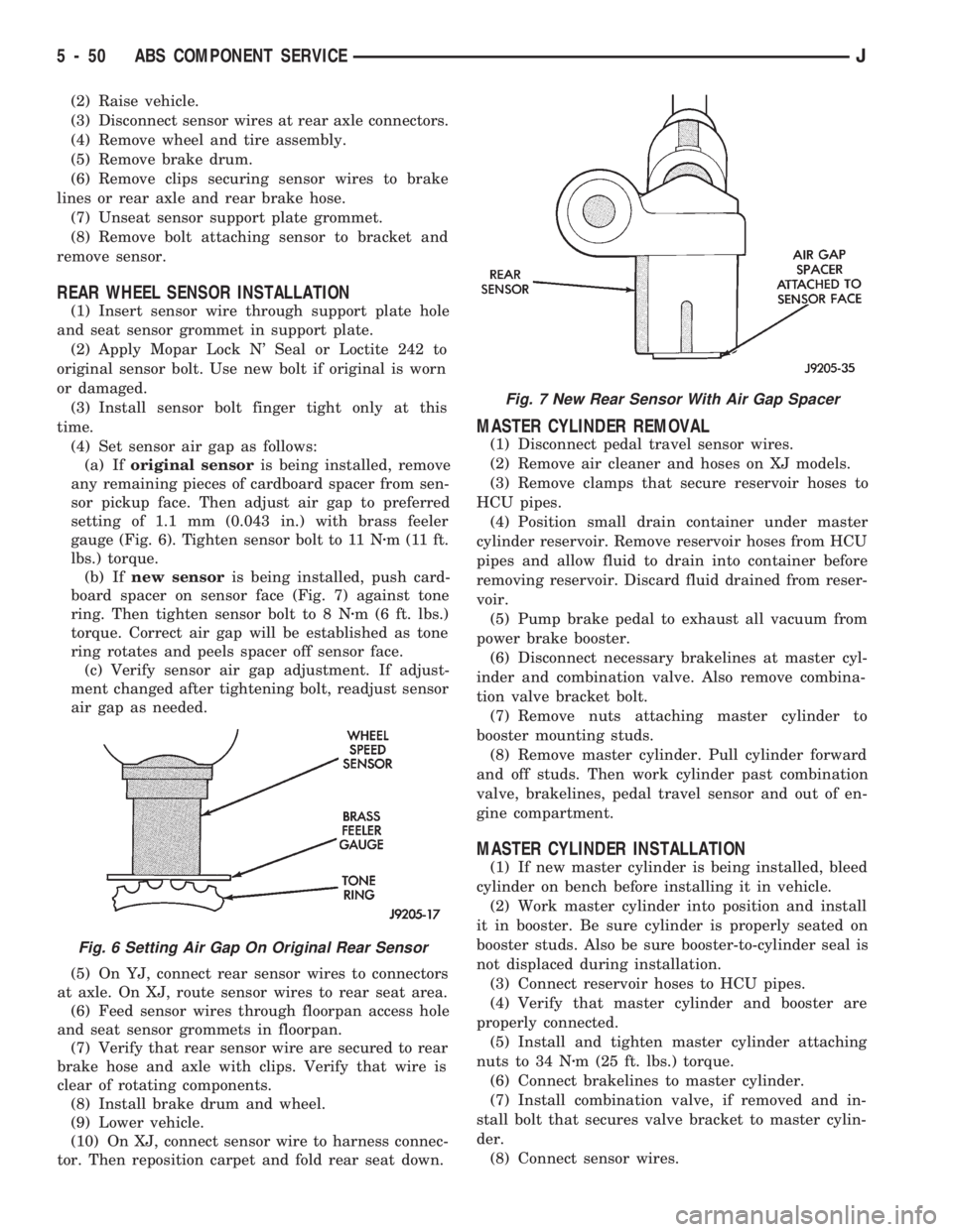
setting of 1.1 mm (0.043 in.) with brass feeler
gauge (Fig. 6). Tighten sensor bolt to 11 Nzm (11 ft.
lbs.) torque.
(b) Ifnew sensoris being installed, push card-
board spacer on sensor face (Fig. 7) against tone
ring. Then tighten sensor bolt to 8 Nzm (6 ft. lbs.)
torque. Correct air gap will be established as tone
ring rotates and peels spacer off sensor face.
(c) Verify sensor air gap adjustment. If adjust-
ment changed after tightening bolt, readjust sensor
air gap as needed.
(5) On YJ, connect rear sensor wires to connectors
at axle. On XJ, route sensor wires to rear seat area.
(6) Feed sensor wires through floorpan access hole
and seat sensor grommets in floorpan.
(7) Verify that rear sensor wire are secured to rear
brake hose and axle with clips. Verify that wire is
clear of rotating components.
(8) Install brake drum and wheel.
(9) Lower vehicle.
(10) On XJ, connect sensor wire to harness connec-
tor. Then reposition carpet and fold rear seat down.
MASTER CYLINDER REMOVAL
(1) Disconnect pedal travel sensor wires.
(2) Remove air cleaner and hoses on XJ models.
(3) Remove clamps that secure reservoir hoses to
HCU pipes.
(4) Position small drain container under master
cylinder reservoir. Remove reservoir hoses from HCU
pipes and allow fluid to drain into container before
removing reservoir. Discard fluid drained from reser-
voir.
(5) Pump brake pedal to exhaust all vacuum from
power brake booster.
(6) Disconnect necessary brakelines at master cyl-
inder and combination valve. Also remove combina-
tion valve bracket bolt.
(7) Remove nuts attaching master cylinder to
booster mounting studs.
(8) Remove master cylinder. Pull cylinder forward
and off studs. Then work cylinder past combination
valve, brakelines, pedal travel sensor and out of en-
gine compartment.
MASTER CYLINDER INSTALLATION
(1) If new master cylinder is being installed, bleed
cylinder on bench before installing it in vehicle.
(2) Work master cylinder into position and install
it in booster. Be sure cylinder is properly seated on
booster studs. Also be sure booster-to-cylinder seal is
not displaced during installation.
(3) Connect reservoir hoses to HCU pipes.
(4) Verify that master cylinder and booster are
properly connected.
(5) Install and tighten master cylinder attaching
nuts to 34 Nzm (25 ft. lbs.) torque.
(6) Connect brakelines to master cylinder.
(7) Install combination valve, if removed and in-
stall bolt that secures valve bracket to master cylin-
der.
(8) Connect sensor wires.
Fig. 6 Setting Air Gap On Original Rear Sensor
Fig. 7 New Rear Sensor With Air Gap Spacer
5 - 50 ABS COMPONENT SERVICEJ