Page 1163 of 1784
FRONT BEARING, SEAL AND PIN
INSTALLATION
(1) Press front bearing on input shaft. Then secure
bearing with thickest snap ring that will fit in shaft
groove (Fig. 70).
(2) Press front bearing on cluster gear. Then se-
cure bearing with thickest snap ring that will fit in
ring groove on gear (Fig. 71).
(3) Install new oil seals in front bearing retainer and
adapter housing (Fig. 72). Installation depth for bearing
retainer seal is 10.5 - 11.5 mm (0.414 - 0.453 in.).
(4) Install reverse shaft and shaft retaining pin in
adapter housing. Then install access hole plug with
torx bit (Fig. 73).
Fig. 70 Selecting Input Shaft Front Bearing Snap
Ring
Fig. 71 Selecting Cluster Gear Front Bearing Snap
Ring
Fig. 72 Oil Seal Installation
Fig. 73 Installing Reverse Shaft Pin
21 - 52 AX 15 MANUAL TRANSMISSIONJ
Page 1164 of 1784

(5) Lubricate reverse shaft and gear components
with Mopar 75W-90 gear lubricant.
OUTPUT SHAFT ASSEMBLY
(1) Lubricate output shaft journals, gears and nee-
dle bearings with Mopar 75W-90 gear lubricant.
(2) Install third gear and needle bearing on shaft
(Fig. 63)
(3) Install synchro ring on third gear (Fig. 63).
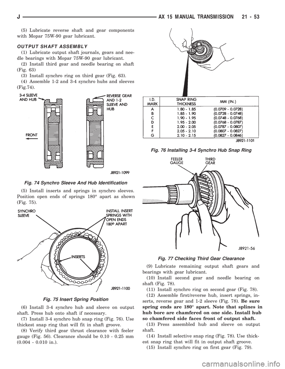
(4) Assemble 1-2 and 3-4 synchro hubs and sleeves
(Fig.74).
(5) Install inserts and springs in synchro sleeves.
Position open ends of springs 180É apart as shown
(Fig. 75).
(6) Install 3-4 synchro hub and sleeve on output
shaft. Press hub onto shaft if necessary.
(7) Install 3-4 synchro hub snap ring (Fig. 76). Use
thickest snap ring that will fit in shaft groove.
(8) Verify third gear thrust clearance with feeler
gauge (Fig. 56). Clearance should be 0.10 - 0.25 mm
(0.004 - 0.010 in.).(9) Lubricate remaining output shaft gears and
bearings with gear lubricant.
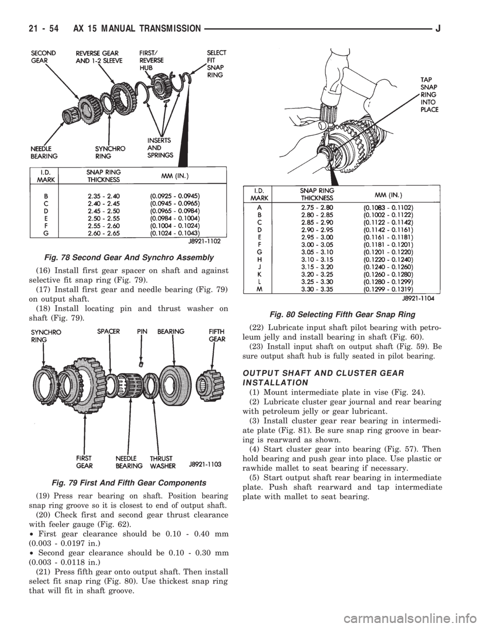
(10) Install second gear and needle bearing on
shaft (Fig. 78).
(11) Install synchro ring on second gear (Fig. 78).
(12) Assemble first/reverse hub, insert springs, in-
serts, reverse gear and 1-2 sleeve (Fig. 78).Be sure
spring ends are 180É apart. Note that splines in
hub bore are chamfered on one side. Install hub
so chamfered side faces front of output shaft.
(13) Press assembled hub and sleeve on output
shaft.
(14) Install selective snap ring (Fig. 78). Use thick-
est snap ring that will fit in output shaft groove.
(15) Install synchro ring on first gear (Fig. 79).
Fig. 74 Synchro Sleeve And Hub Identification
Fig. 75 Insert Spring Position
Fig. 76 Installing 3-4 Synchro Hub Snap Ring
Fig. 77 Checking Third Gear Clearance
JAX 15 MANUAL TRANSMISSION 21 - 53
Page 1165 of 1784

(16) Install first gear spacer on shaft and against
selective fit snap ring (Fig. 79).
(17) Install first gear and needle bearing (Fig. 79)
on output shaft.
(18) Install locating pin and thrust washer on
shaft (Fig. 79).
(19) Press rear bearing on shaft. Position bearing
snap ring groove so it is closest to end of output shaft.
(20) Check first and second gear thrust clearance
with feeler gauge (Fig. 62).
²First gear clearance should be 0.10 - 0.40 mm
(0.003 - 0.0197 in.)
²Second gear clearance should be 0.10 - 0.30 mm
(0.003 - 0.0118 in.)
(21) Press fifth gear onto output shaft. Then install
select fit snap ring (Fig. 80). Use thickest snap ring
that will fit in shaft groove.(22) Lubricate input shaft pilot bearing with petro-
leum jelly and install bearing in shaft (Fig. 60).
(23) Install input shaft on output shaft (Fig. 59). Be
sure output shaft hub is fully seated in pilot bearing.
OUTPUT SHAFT AND CLUSTER GEAR
INSTALLATION
(1) Mount intermediate plate in vise (Fig. 24).
(2) Lubricate cluster gear journal and rear bearing
with petroleum jelly or gear lubricant.
(3) Install cluster gear rear bearing in intermedi-
ate plate (Fig. 81). Be sure snap ring groove in bear-
ing is rearward as shown.
(4) Start cluster gear into bearing (Fig. 57). Then
hold bearing and push gear into place. Use plastic or
rawhide mallet to seat bearing if necessary.
(5) Start output shaft rear bearing in intermediate
plate. Push shaft rearward and tap intermediate
plate with mallet to seat bearing.
Fig. 78 Second Gear And Synchro Assembly
Fig. 79 First And Fifth Gear Components
Fig. 80 Selecting Fifth Gear Snap Ring
21 - 54 AX 15 MANUAL TRANSMISSIONJ
Page 1166 of 1784
(6) Install snap rings on cluster and output shaft
rearbearings only (Fig. 82). Do not install front
bearing snap rings at this time.(7) Install reverse idler gear and shaft (Fig. 83).
(8) Position rear bearing retainer over output shaft
and rear bearing.Be sure bearing retainer tab is
engaged in reverse idler shaft notch (Fig. 84).
(9) Install and tighten rear bearing retainer bolts
to 18 Nzm (13 ft-lbs).
Fig. 81 Installing Cluster Gear Rear Bearing
Fig. 82 Installing Rear Bearing Snap Rings
Fig. 83 Installing Reverse Idler Gear And Shaft
Fig. 84 Installing Rear Bearing Retainer
JAX 15 MANUAL TRANSMISSION 21 - 55
Page 1167 of 1784
SHIFT RAIL AND FORK INSTALLATION
The shift rail interlock pins, balls and plugs must
be installed in the correct sequence for proper shift-
ing. Refer to the installation diagram (Fig. 85) dur-
ing assembly.
Coat the intermediate plate shift rail bores and
the interlock balls, pins and plugs with a heavy
coating of petroleum jelly before assembly. The
jelly will hold the interlock components in place
making installation easier. Use a pencil magnet
to hold and insert the interlocks. Then use a
small screwdriver to push the interlock compo-
nents into place.
(1) Coat reverse rail interlock pin with petroleum
jelly and install pin in rail (Fig. 86).
Fig. 85 Shift Rail Ball-Plug-Pin Position
Fig. 86 Installing Reverse Shift Rail Interlock Pin
21 - 56 AX 15 MANUAL TRANSMISSIONJ
Page 1168 of 1784
(2) Install reverse shift rail in intermediate plate
(Fig. 87).
(3) Install reverse shift rail C-ring (Fig. 51).
(4) Position 1-2 and 3-4 shift forks in synchro
sleeves (Fig. 88).
(5) Coat reverse rail lock ball with petroleum jelly.
Then tilt reverse shift fork upward and insert ball in
intermediate plate (Fig. 89).(6) Coat 1-2 shift rail interlock plug with petro-
leum jelly and install it in intermediate plate bore
(Fig. 90).
(7) Coat 1-2 shift rail interlock pin with petroleum
jelly and insert it in shift rail (Fig. 91).
Fig. 87 Installing Reverse Shift Rail And Fork
Fig. 88 Shift Fork Installation
Fig. 89 Installing Reverse Shift Rail Lock Ball
Fig. 90 Installing 1-2 Shift Rail Interlock Plug
Fig. 91 Installing 1-2 Shift Rail Interlock Pin
JAX 15 MANUAL TRANSMISSION 21 - 57
Page 1169 of 1784
(8) Install 1-2 shift rail in intermediate plate and
1-2 fork (Fig. 92).
(9) Coat 3-4 shift rail interlock plug with petro-
leum jelly and install plug in intermediate plate (Fig.
93).
(10) Install 3-4 shift rail in intermediate plate and
in both shift forks (Fig. 94).
(11) Verify that none of interlock balls, plugs, or
pins were displaced during shift rail installation.
(12) Install and tighten shift fork setscrews to 20
Nzm (14 ft. lbs.) torque (Fig. 95).
(13) Install 1-2 and 3-4 shift rail C-rings (Fig. 96).
(14) Insert fifth gear shift rail through reverse
shift fork.Then slide rail into intermediate plate
just far enough to secure interlock ball. Do not
fully install shift rail at this time.
Fig. 94 Installing 3-4 Shift Rail
Fig. 95 Installing Shift Fork Set Screws
Fig. 96 Installing Shift Rail C-Rings
Fig. 92 Installing 1-2 Shift Rail
Fig. 93 Installing 3-4 Shift Rail Interlock Plug
21 - 58 AX 15 MANUAL TRANSMISSIONJ
Page 1170 of 1784
FIFTH-REVERSE GEAR AND SHIFT
COMPONENT INSTALLATION
(1) Install thrust ring lock ball in cluster gear
journal (Fig. 97). Use petroleum jelly to hold ball in
place.
(2) Install fifth gear thrust ring (Fig. 98). Be sure
thrust ring notch fits over lock ball.
(3) Assemble counter fifth gear, synchro sleeve, in-
serts and insert springs (Fig. 99).
(4) Lubricate two-piece bearing with petroleum
jelly and install it in counter fifth gear (Fig. 100).
(5) Install counter fifth gear and synchro assembly
on cluster gear journal (Fig. 101).
Fig. 97 Installing Thrust Ring Lock Ball
Fig. 98 Installing Fifth Gear Thrust Ring
Fig. 99 Assembling Fifth Gear And Synchro
Assembly
Fig. 100 Installing Counter Fifth Gear Bearing
Fig. 101 Installing Counter Fifth Gear And Sleeve
JAX 15 MANUAL TRANSMISSION 21 - 59