1994 JEEP CHEROKEE service
[x] Cancel search: servicePage 32 of 1784
FRONT WHEEL BEARINGS
Only 2WD XJ vehicles are equipped with front
wheel bearings. XJ vehicles have semi-floating axle
shafts and axle shaft bearings that are lubricated via
differential lube oil.
RECOMMENDED MAINTENANCEÐ2WD XJ
VEHICLES
The front wheel bearings should be lubricated (re-
packed) at the same time as front brake pad/caliper
service is conducted.
LUBRICANT SPECIFICATION
Wheel bearings should be lubricated with a lubri-
cant that is identified as NLGI GC-LB lubricant.
INSPECTION/LUBRICATION
(1) Remove the wheel/tire and the disc brake cali-
per.Do not disconnect the caliper brake fluid
hose unless the caliper must also be removed for
maintenance. Support the caliper with a hanger
to prevent brake fluid hose damage.
(2) Remove the dust cap, the cotter pin, the nut re-
tainer, the adjustment nut, and the thrust washer
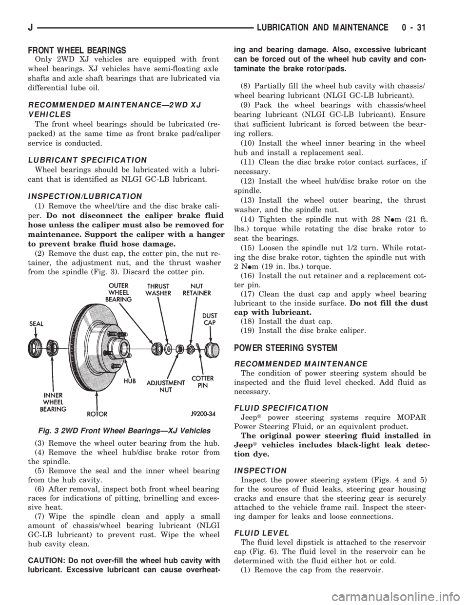
from the spindle (Fig. 3). Discard the cotter pin.
(3) Remove the wheel outer bearing from the hub.
(4) Remove the wheel hub/disc brake rotor from
the spindle.
(5) Remove the seal and the inner wheel bearing
from the hub cavity.
(6) After removal, inspect both front wheel bearing
races for indications of pitting, brinelling and exces-
sive heat.
(7) Wipe the spindle clean and apply a small
amount of chassis/wheel bearing lubricant (NLGI
GC-LB lubricant) to prevent rust. Wipe the wheel
hub cavity clean.
CAUTION: Do not over-fill the wheel hub cavity with
lubricant. Excessive lubricant can cause overheat-ing and bearing damage. Also, excessive lubricant
can be forced out of the wheel hub cavity and con-
taminate the brake rotor/pads.
(8) Partially fill the wheel hub cavity with chassis/
wheel bearing lubricant (NLGI GC-LB lubricant).
(9) Pack the wheel bearings with chassis/wheel
bearing lubricant (NLGI GC-LB lubricant). Ensure
that sufficient lubricant is forced between the bear-
ing rollers.
(10) Install the wheel inner bearing in the wheel
hub and install a replacement seal.
(11) Clean the disc brake rotor contact surfaces, if
necessary.
(12) Install the wheel hub/disc brake rotor on the
spindle.
(13) Install the wheel outer bearing, the thrust
washer, and the spindle nut.
(14) Tighten the spindle nut with 28 NIm (21 ft.
lbs.) torque while rotating the disc brake rotor to
seat the bearings.
(15) Loosen the spindle nut 1/2 turn. While rotat-
ing the disc brake rotor, tighten the spindle nut with
2NIm (19 in. lbs.) torque.
(16) Install the nut retainer and a replacement cot-
ter pin.
(17) Clean the dust cap and apply wheel bearing
lubricant to the inside surface.Do not fill the dust
cap with lubricant.
(18) Install the dust cap.
(19) Install the disc brake caliper.
POWER STEERING SYSTEM
RECOMMENDED MAINTENANCE
The condition of power steering system should be
inspected and the fluid level checked. Add fluid as
necessary.
FLUID SPECIFICATION
Jeeptpower steering systems require MOPAR
Power Steering Fluid, or an equivalent product.
The original power steering fluid installed in
Jeeptvehicles includes black-light leak detec-
tion dye.
INSPECTION
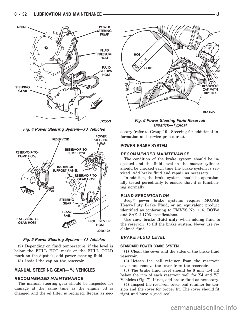
Inspect the power steering system (Figs. 4 and 5)
for the sources of fluid leaks, steering gear housing
cracks and ensure that the steering gear is securely
attached to the vehicle frame rail. Inspect the steer-
ing damper for leaks and loose connections.
FLUID LEVEL
The fluid level dipstick is attached to the reservoir
cap (Fig. 6). The fluid level in the reservoir can be
determined with the fluid either hot or cold.
(1) Remove the cap from the reservoir.
Fig. 3 2WD Front Wheel BearingsÐXJ Vehicles
JLUBRICATION AND MAINTENANCE 0 - 31
Page 33 of 1784
(2) Depending on fluid temperature, if the level is
below the FULL HOT mark or the FULL COLD
mark on the dipstick, add power steering fluid.
(3) Install the cap on the reservoir.
MANUAL STEERING GEARÐYJ VEHICLES
RECOMMENDED MAINTENANCE
The manual steering gear should be inspected for
damage at the same time as the engine oil is
changed and the oil filter is replaced. Repair as nec-essary (refer to Group 19ÐSteering for additional in-
formation and service procedures).
POWER BRAKE SYSTEM
RECOMMENDED MAINTENANCE
The condition of the brake system should be in-
spected and the fluid level in the master cylinder
should be checked each time the brake system is ser-
viced. Add brake fluid and repair as necessary.
In addition, the brake system should be operation-
ally tested periodically to ensure that it is function-
ing normally.
FLUID SPECIFICATION
Jeeptpower brake systems require MOPAR
Heavy-Duty Brake Fluid, or an equivalent product
identified as conforming to FMVSS No. 116, DOT-3
and SAE J-1703 specifications.
Usenew brake fluid onlywhen adding fluid to
the reservoir, to fill the brake system. Never use re-
claimed fluid.
BRAKE FLUID LEVEL
STANDARD POWER BRAKE SYSTEM
(1) Clean the cover and the sides of the brake fluid
reservoir.
(2) Detach the bail retainer from the reservoir
cover and remove the cover from the reservoir.
(3) The brake fluid level should be 6 mm (1/4 in)
below the rim of each reservoir well for XJ and YJ
Vehicles (Fig. 7). If not, add brake fluid as necessary.
(4) Inspect the reservoir cover bail retainer for ten-
sion and the cover for proper fit. The cover should fit
tight and have a good seal.
Fig. 4 Power Steering SystemÐXJ Vehicles
Fig. 5 Power Steering SystemÐYJ Vehicles
Fig. 6 Power Steering Fluid Reservoir
DipstickÐTypical
0 - 32 LUBRICATION AND MAINTENANCEJ
Page 38 of 1784
FRONT SUSPENSION AND AXLE
CONTENTS
page page
AXLE NOISE/VIBRATION DIAGNOSIS....... 16
FRONT WHEEL ALIGNMENT............... 5
GENERAL INFORMATION.................. 1
MODEL 30 AXLE AND TUBE AXLE (2WD) . . 20TORQUE SPECIFICATIONS................ 47
XJ FRONT SUSPENSION................. 10
YJ FRONT SUSPENSION................. 13
GENERAL INFORMATION
FRONT SUSPENSION
XJ VEHICLES
The Cherokee front suspension is a link/coil design
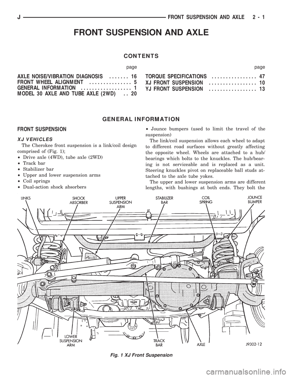
comprised of (Fig. 1);
²Drive axle (4WD), tube axle (2WD)
²Track bar
²Stabilizer bar
²Upper and lower suspension arms
²Coil springs
²Dual-action shock absorbers²Jounce bumpers (used to limit the travel of the
suspension)
The link/coil suspension allows each wheel to adapt
to different road surfaces without greatly affecting
the opposite wheel. Wheels are attached to a hub/
bearings which bolts to the knuckles. The hub/bear-
ing is not serviceable and is replaced as a unit.
Steering knuckles pivot on replaceable ball studs at-
tached to the axle tube yokes.
The upper and lower suspension arms are different
lengths, with bushings at both ends. They bolt the
Fig. 1 XJ Front Suspension
JFRONT SUSPENSION AND AXLE 2 - 1
Page 40 of 1784
The shocks absorbers dampen jounce and rebound
of the vehicle over various road conditions. The top of
the shock absorbers are bolted to the frame. The bot-
tom of the shocks are bolted to the axle bracket.
The stabilizer bar is used to minimize vehicle front
sway during turns. The spring steel bar helps to con-
trol the vehicle body in relationship to the suspen-
sion. The bar extends across the front underside of
the chassis and connects to the frame rails. Links are
connected from the bar to the axle brackets. Stabi-
lizer bar mounts are isolated by rubber bushings.
The track bar is used to minimize front axle side-
to-side movement. The track bar is attached to a
frame rail bracket and the axle bracket.
The bar uses bushings at both ends.
FRONT DRIVE AXLE
It is not necessary to remove the complete axle
from the vehicle for routine differential service. If
the differential housing or axle shaft tubes are dam-
aged, the complete axle assembly can be removed
and serviced.
For complete drive axle assembly removal and in-
stallation refer to Drive Axle Assembly Replacement
in this Group.
The removable cover provides for servicing without
removing axle from vehicle.
The integral type housing, hypoid gear design has
the centerline of the pinion set above the centerline
of the ring gear.
The Model 30 axle has the assembly part number
and gear ratio listed on a tag. The tag is attached to
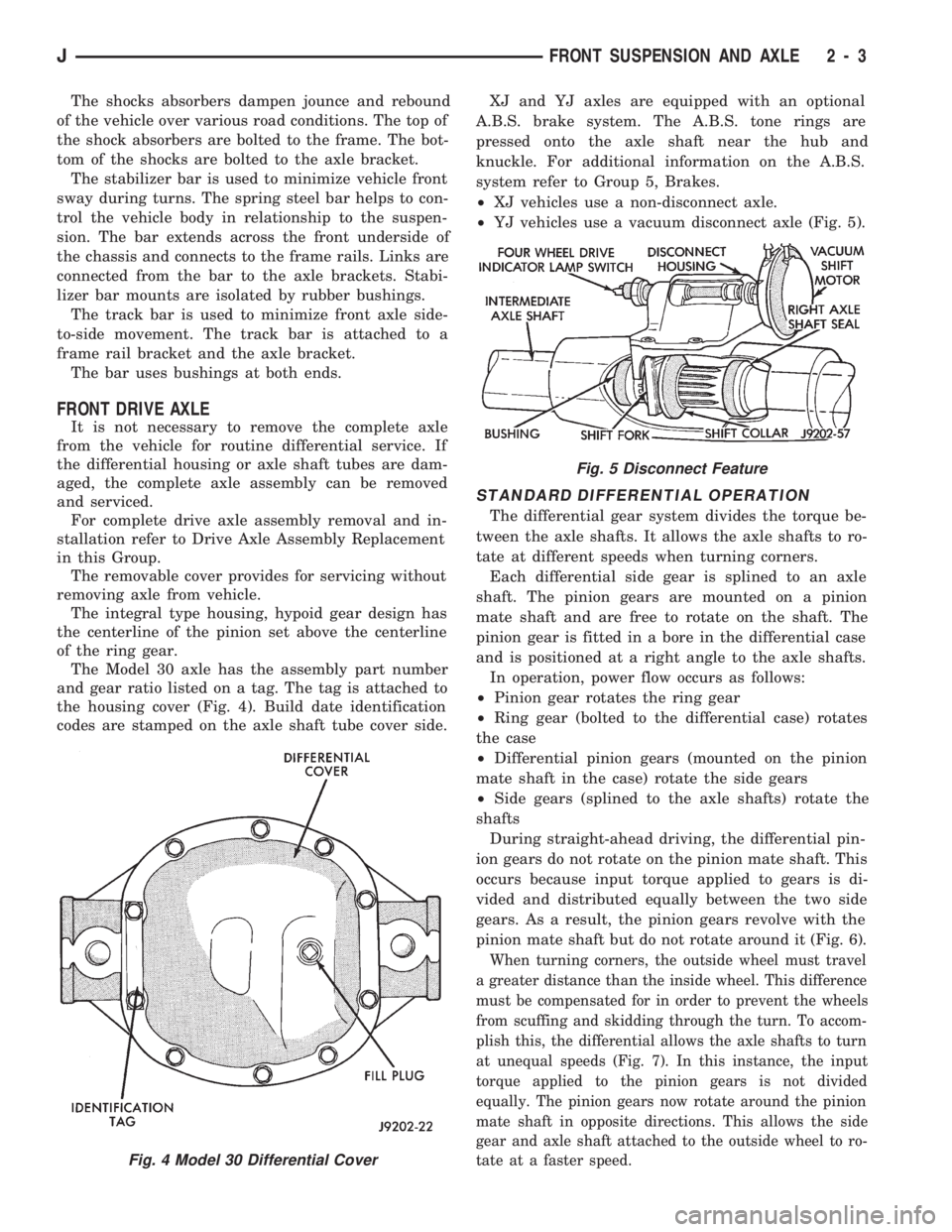
the housing cover (Fig. 4). Build date identification
codes are stamped on the axle shaft tube cover side.XJ and YJ axles are equipped with an optional
A.B.S. brake system. The A.B.S. tone rings are
pressed onto the axle shaft near the hub and
knuckle. For additional information on the A.B.S.
system refer to Group 5, Brakes.
²XJ vehicles use a non-disconnect axle.
²YJ vehicles use a vacuum disconnect axle (Fig. 5).
STANDARD DIFFERENTIAL OPERATION
The differential gear system divides the torque be-
tween the axle shafts. It allows the axle shafts to ro-
tate at different speeds when turning corners.
Each differential side gear is splined to an axle
shaft. The pinion gears are mounted on a pinion
mate shaft and are free to rotate on the shaft. The
pinion gear is fitted in a bore in the differential case
and is positioned at a right angle to the axle shafts.
In operation, power flow occurs as follows:
²Pinion gear rotates the ring gear
²Ring gear (bolted to the differential case) rotates
the case
²Differential pinion gears (mounted on the pinion
mate shaft in the case) rotate the side gears
²Side gears (splined to the axle shafts) rotate the
shafts
During straight-ahead driving, the differential pin-
ion gears do not rotate on the pinion mate shaft. This
occurs because input torque applied to gears is di-
vided and distributed equally between the two side
gears. As a result, the pinion gears revolve with the
pinion mate shaft but do not rotate around it (Fig. 6).
When turning corners, the outside wheel must travel
a greater distance than the inside wheel. This difference
must be compensated for in order to prevent the wheels
from scuffing and skidding through the turn. To accom-
plish this, the differential allows the axle shafts to turn
at unequal speeds (Fig. 7). In this instance, the input
torque applied to the pinion gears is not divided
equally. The pinion gears now rotate around the pinion
mate shaft in opposite directions. This allows the side
gear and axle shaft attached to the outside wheel to ro-
tate at a faster speed.
Fig. 4 Model 30 Differential Cover
Fig. 5 Disconnect Feature
JFRONT SUSPENSION AND AXLE 2 - 3
Page 47 of 1784
XJ FRONT SUSPENSION
INDEX
page page
Axle Bushing Replacement................. 11
Coil Spring............................. 13
Lower Suspension Arm.................... 11
Service Information....................... 10
Shock Absorber.......................... 12Spring and Shock Diagnosis................ 12
Stabilizer Bar............................ 10
Track Bar.............................. 10
Upper Suspension Arm.................... 11
SERVICE INFORMATION
CAUTION: Suspension components that use rubber
bushings should be tightened with the vehicle at
the normal height. It is important to have the
springs supporting the weight of the vehicle when
the fasteners are torqued. If the springs are not at
their normal ride position, vehicle ride comfort
could be affected along with premature bushing
wear. Rubber bushings must never be lubricated.
TRACK BAR
REMOVAL
(1) Raise and support the vehicle.
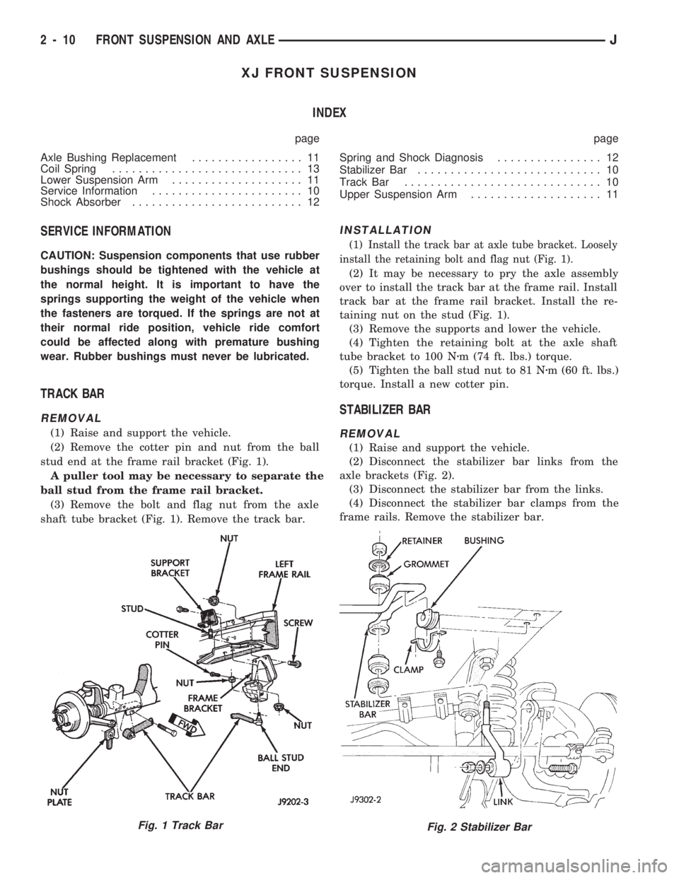
(2) Remove the cotter pin and nut from the ball
stud end at the frame rail bracket (Fig. 1).
A puller tool may be necessary to separate the
ball stud from the frame rail bracket.
(3) Remove the bolt and flag nut from the axle
shaft tube bracket (Fig. 1). Remove the track bar.
INSTALLATION
(1) Install the track bar at axle tube bracket. Loosely
install the retaining bolt and flag nut (Fig. 1).
(2) It may be necessary to pry the axle assembly
over to install the track bar at the frame rail. Install
track bar at the frame rail bracket. Install the re-
taining nut on the stud (Fig. 1).
(3) Remove the supports and lower the vehicle.
(4) Tighten the retaining bolt at the axle shaft
tube bracket to 100 Nzm (74 ft. lbs.) torque.
(5) Tighten the ball stud nut to 81 Nzm (60 ft. lbs.)
torque. Install a new cotter pin.
STABILIZER BAR
REMOVAL
(1) Raise and support the vehicle.
(2) Disconnect the stabilizer bar links from the
axle brackets (Fig. 2).
(3) Disconnect the stabilizer bar from the links.
(4) Disconnect the stabilizer bar clamps from the
frame rails. Remove the stabilizer bar.
Fig. 2 Stabilizer BarFig. 1 Track Bar
2 - 10 FRONT SUSPENSION AND AXLEJ
Page 50 of 1784
COIL SPRING
REMOVAL
(1) Raise and support the vehicle. Position a hy-
draulic jack under the axle to support it.
(2) Remove the wheel if necessary.
(3) Mark and disconnect the front propeller shaft
from the axle.
(4) Disconnect the lower suspension arms from the
axle (Fig. 6).
(5) Disconnect the stabilizer bar link and shock ab-
sorber from the axle.
(6) Disconnect the track bar from the frame rail
bracket.
(7) Disconnect the drag link from the pitman arm.
(8) Lower the axle until the spring is free from the
upper mount. Remove the coil spring clip (Fig. 6) and
remove the spring.
(9) Remove the jounce bumper if necessary from
the upper spring mount (Fig. 6).
INSTALLATION
(1) Install the jounce bumper on the upper spring
mount. Tighten the bolt to 42 Nzm (31 ft. lbs.) torque
(Fig. 6).
(2) Position the coil spring on the axle pad. Install
the spring clip and bolt (Fig. 6). Tighten bolt to 21
Nzm (16 ft. lbs.) torque.
(3) Raise the axle into position until the spring
seats in the upper mount.
(4) Connect the stabilizer bar links and shock ab-
sorbers to the axle bracket. Connect the track bar to
the frame rail bracket.
(5) Install the lower suspension arms to the axle.
DO NOT TIGHTEN AT THIS TIME.
(6) Install the front propeller shaft to the axle.
(7) Remove the supports and lower the vehicle.
(8) Tighten lower suspension arms nuts to 115
Nzm (85 ft. lbs.) torque.
YJ FRONT SUSPENSION
INDEX
page page
Leaf Spring............................. 14
Leaf Spring Eye Bushing Replacement........ 15
Service Information....................... 13
Shock Absorber.......................... 14Spring and Shock Diagnosis................ 14
Stabilizer Bar............................ 14
Track Bar.............................. 13
SERVICE INFORMATION
It is important to have the springs supporting
the weight of the vehicle when the track bar fas-
teners are being torqued. If the springs are not
at their normal ride position, vehicle ride com-
fort could be affected along with premature rub-
ber bushing wear.
TRACK BAR
REMOVAL
(1) Raise and support the vehicle.
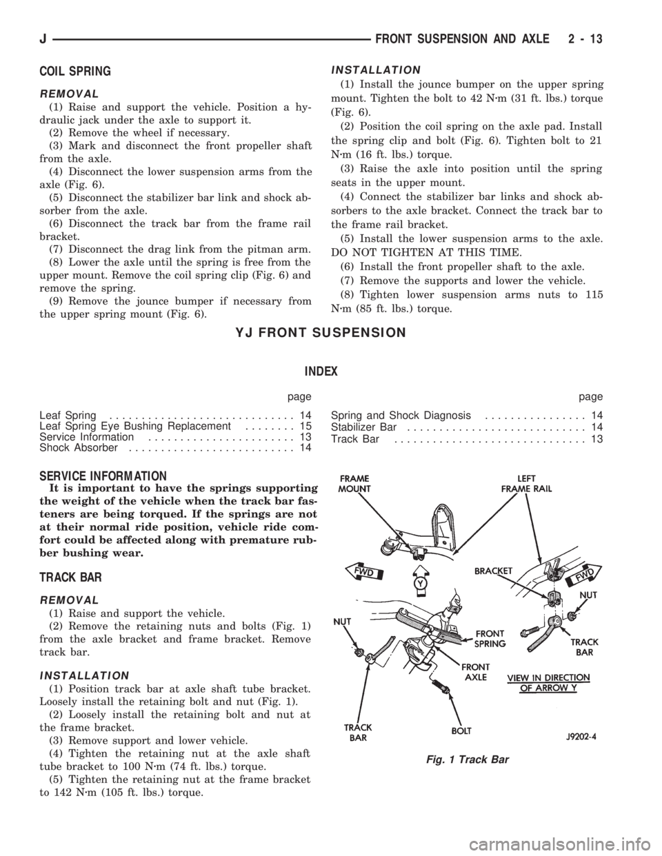
(2) Remove the retaining nuts and bolts (Fig. 1)
from the axle bracket and frame bracket. Remove
track bar.
INSTALLATION
(1) Position track bar at axle shaft tube bracket.
Loosely install the retaining bolt and nut (Fig. 1).
(2) Loosely install the retaining bolt and nut at
the frame bracket.
(3) Remove support and lower vehicle.
(4) Tighten the retaining nut at the axle shaft
tube bracket to 100 Nzm (74 ft. lbs.) torque.
(5) Tighten the retaining nut at the frame bracket
to 142 Nzm (105 ft. lbs.) torque.
Fig. 1 Track Bar
JFRONT SUSPENSION AND AXLE 2 - 13
Page 53 of 1784
AXLE NOISE/VIBRATION DIAGNOSIS
INDEX
page page
Driveline Snap........................... 17
Gear and Bearing Noise................... 16
General Information....................... 16Low Speed Knock........................ 17
Vibration............................... 17
GENERAL INFORMATION
Axle bearing problem conditions are usually caused
by:
²Insufficient or incorrect lubricant
²Foreign matter/water contamination
²Incorrect bearing preload torque adjustment
²Incorrect backlash (to tight)
When serviced, the bearings must be cleaned thor-
oughly. They should be dried with lint-free shop tow-
els.Never dry bearings with compressed air.
This will overheat them and brinell the bearing
surfaces. This will result in noisy operation after
repair.
Axle gear problem conditions are usually the result
of:
²Insufficient lubrication
²Incorrect or contaminated lubricant
²Overloading (excessive engine torque) or exceeding
vehicle weight capacity
²Incorrect clearance or backlash adjustment
Insufficient lubrication is usually the result of a
housing cover leak. It can also be from worn axle
shaft or pinion gear seals. Check for cracks or porous
areas in the housing or tubes.
Using the wrong lubricant will cause overheating
and gear failure. Gear tooth cracking and bearing
spalling are indicators of this.
Axle component breakage is most often the result
of:
²Severe overloading
²Insufficient lubricant
²Incorrect lubricant
²Improperly tightened components
Overloading occurs when towing heavier than rec-
ommended loads. Component breakage can occur
when the wheels are spun excessively. Incorrect lu-
bricant quantity contributes to breakage. Loose dif-
ferential components can also cause breakage.
Incorrect bearing preload or gear backlash will not
result in component breakage. Mis-adjustment will
produce enough noise to cause service repair before a
failure occurs. If a mis-adjustment condition is not
corrected, component failure can result.
Excessive bearing preload may not be noisy. This
condition will cause high temperature which can re-
sult in bearing failure.
GEAR AND BEARING NOISE
GEAR NOISE
Axle gear noise can be caused by insufficient lubri-
cant. Incorrect backlash, tooth contact, or worn/dam-
aged gears can cause noise.
Gear noise usually happens at a specific speed
range. The range is 30 to 40 mph, or above 50 mph.
The noise can also occur during a specific type of
driving condition. These conditions are acceleration,
deceleration, coast, or constant load.
When road testing, accelerate the vehicle to the
speed range where the noise is the greatest. Shift
out-of-gear and coast through the peak-noise range.
If the noise stops or changes greatly, check for insuf-
ficient lubricant. Incorrect ring gear backlash, or
gear damage can cause noise changes.
Differential side and pinion gears can be checked
by turning the vehicle. They usually do not cause
noise in straight-ahead driving. These gears are
loaded during vehicle turns. If noise does occur dur-
ing vehicle turns, the side or pinion gears could be
worn or damaged. A worn pinion gear mate shaft can
also cause a snapping or a knocking noise.
BEARING NOISE
The axle shaft, differential and pinion gear bear-
ings can all produce noise when worn or damaged.
Bearing noise can be either a whining, or a growling
sound.
Pinion gear bearings have a constant-pitch noise.
This noise changes only with vehicle speed. Pinion
bearing noise will be higher because it rotates at a
faster rate. Drive the vehicle and load the differen-
tial. If bearing noise occurs the pinion rear bearing is
the source of the noise. If the bearing noise is heard
during a coast, front bearing is the source.
Worn, damaged differential bearings usually pro-
duce a low pitch noise. Differential bearing noise is
similar to pinion bearing. The pitch of differential
bearing noise is also constant and varies only with
vehicle speed.
Axle shaft bearings produce noise and vibration
when worn or damaged. The noise generally changes
when the bearings are loaded. Road test the vehicle.
Turn the vehicle sharply to the left and to the right.
This will load the bearings and change the noise
2 - 16 FRONT SUSPENSION AND AXLEJ
Page 55 of 1784
SERVICE DIAGNOSIS
2 - 18 FRONT SUSPENSION AND AXLEJ