1994 JEEP CHEROKEE battery
[x] Cancel search: batteryPage 482 of 1784
POWER MIRRORS
CONTENTS
page page
DIAGNOSIS............................. 1
GENERAL.............................. 1
POWER MIRROR REPLACEMENT........... 4POWER MIRROR SWITCH REPLACEMENT . . . 4
POWER MIRROR SWITCH TESTING......... 2
GENERAL
For information concerning wiring or connectors,
refer to Group 8W - Wiring Diagrams.
The mirror control switch contains two separate
switches, the operating switch and the selector
switch.
Each mirror has two reversible motors: one to ad-
just the mirror view up and down, the other to adjust
the mirror view right and left. The driver operates
three switches that control the polarity of the voltage
to the motors. The mirror select switch directs these
control voltages to either the right or left mirror.
The mirror select switch must be set to L or R to
direct current flow. If the mirror select switch is set
on R and the up-down switch is moved to the UP po-
sition, the voltage path is:
²through the U contact of switch 1
²to pin E
²to the up-down motor in the right mirror.
The ground path is:
²through pin D
²through the mirror select switch contacts
²to the U contacts of switch 3 and switch 2
²to pin F
²to ground.
The right motor runs and tilts the mirror up.
If the switch is pushed to the DOWN position, thesame motor receives voltage. Now the polarity is re-
versed, with pin E grounded. The motor runs in the
opposite direction.
The right mirror left-right motor operates in a sim-
ilar manner when the control switch is moved to the
L or R positions.
The left mirror works the same way as the right
mirror when mirror select switch is moved to L posi-
tion and control switch is operated.
DIAGNOSIS
For information concerning wiring or connectors,
refer to Group 8W - Wiring Diagrams.
²Open door. Dome lamps should light. If not, check
dome fuse.
Remove switch, unplug switch connector
²Measure resistance at mirror switch connector pin
F. Meter should read zero ohms, If not, repair open to
ground.
²Measure voltage at mirror switch connector pin G.
Meter should read battery voltage. If not, repair open
to dome fuse.
Install a jumper lead from pin E to pin F.
²Connect a jumper lead from pin G to: pin A; pin B;
pin C and then pin D. If the mirror moves, replace
switch. If not, repair open to motor and/or replace
motor.
JPOWER MIRRORS 8T - 1
Page 488 of 1784
CHIME/BUZZER WARNING SYSTEMS
CONTENTS
page page
GENERAL.............................. 1
IGNITION KEY WARNING SWITCH REPLACEMENT.4OPERATION/DIAGNOSIS.................. 1
GENERAL
The buzzer or optional chime module is mounted on
the left side of the fuse block (above and to the left of
the brake/clutch pedal). The buzzer or chime sounds
an audible warning tone in any of the following con-
ditions:
²Vehicle lights are ON when the ignition has been
switched OFF and the key is removed and then the
driver's door is opened (except YJ).²The key is in the ignition and the driver's door is
open (On some vehicles, the buzzer will not sound if
the ignition switch is in the ON position).
²The ignition is switched ON and the driver's seat
belt is not buckled. Buzzer will quit after 4 to 8 sec-
onds. Besides the buzzer, a seat belt indicator lamp
turns on as a reminder to fasten seat belt.
OPERATION/DIAGNOSIS
OPERATION
Battery voltage for module operation is supplied to
two pins. Voltage is always present at pin 7. Pin 1
receives voltage when the ignition switch is in the
ON or START position.
SEAT BELT WARNING
The seat belt warning system uses both visual and
audible signals. These consist of a buzzer that is part
of a combined seat belt and key warning buzzer and
a red light on the instrument panel.
The system will always illuminate the seat belt
warning lamp for four to eight seconds when the ig-
nition switch is turned to the ON position. Also, only
if the driver does not fasten his seat belt, the buzzer
will sound during the same time interval. Passenger
belts are not connected to the system.
A timed buzzer-relay is used to operate the system
for the time period. It has a time delay mechanism
and buzzer assembly. Only the driver's seat belt
buckle has a switch that is connected to the system.
KEY-IN-IGNITION WARNING
To sound the key-in-ignition warning, the following
must occur:
²the ignition key warning switch must be closed
²the driver's door jamb switch must be closed.
These conditions ground pin 6 of the module. These
switches are closed when the key is in the ignition
and the driver's door is open.On some vehicles the chime/buzzer will not
sound if the door is open and the key is in the
ON position.
LIGHTS-ON WARNING (EXCEPT YJ)
To sound the lights-on warning, the following must
occur:
²the headlamp switch must be closed
²the driver's door jamb switch must be closed.
These conditions ground pin 6 of the module. These
switches are closed when the headlamp switch is ON
and the driver's door is open.
DIAGNOSIS
If the buzzer/chime unit does not operate as de-
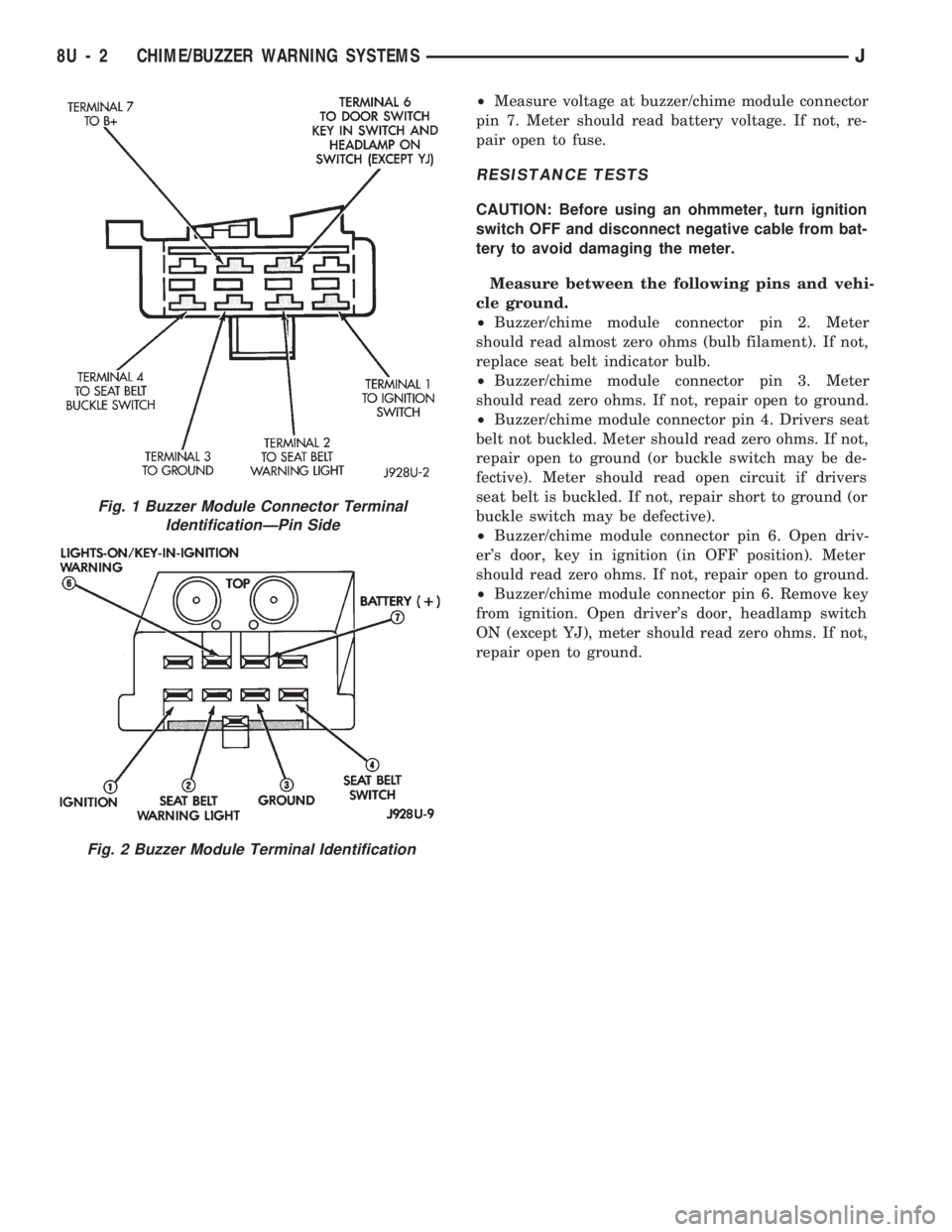
scribed, check the two fuses for pins 1 and 7 (Figs. 1
and 2) and replace as required. If the fuses are not
defective, perform the following tests to determine if
the problem is in the module or in the wiring. Using
a flat head screwdriver, release the locking plastic
clip while carefully pulling out the module. Plug in a
known good module and check its operation. If the
problem is not corrected by replacing the module, re-
move the module and continue as follows:
VOLTAGE TESTS
Ignition in ON position, measure between the
following pins and vehicle ground.
²Measure voltage at buzzer/chime module connector
pin 1. Meter should read battery voltage. If not, re-
pair open to ignition switch.
Turn ignition OFF and remove the key from the ig-
nition.
JCHIME/BUZZER WARNING SYSTEMS 8U - 1
Page 489 of 1784
²Measure voltage at buzzer/chime module connector
pin 7. Meter should read battery voltage. If not, re-
pair open to fuse.
RESISTANCE TESTS
CAUTION: Before using an ohmmeter, turn ignition
switch OFF and disconnect negative cable from bat-
tery to avoid damaging the meter.
Measure between the following pins and vehi-
cle ground.
²Buzzer/chime module connector pin 2. Meter
should read almost zero ohms (bulb filament). If not,
replace seat belt indicator bulb.
²Buzzer/chime module connector pin 3. Meter
should read zero ohms. If not, repair open to ground.
²Buzzer/chime module connector pin 4. Drivers seat
belt not buckled. Meter should read zero ohms. If not,
repair open to ground (or buckle switch may be de-
fective). Meter should read open circuit if drivers
seat belt is buckled. If not, repair short to ground (or
buckle switch may be defective).
²Buzzer/chime module connector pin 6. Open driv-
er's door, key in ignition (in OFF position). Meter
should read zero ohms. If not, repair open to ground.
²Buzzer/chime module connector pin 6. Remove key
from ignition. Open driver's door, headlamp switch
ON (except YJ), meter should read zero ohms. If not,
repair open to ground.
Fig. 2 Buzzer Module Terminal Identification
Fig. 1 Buzzer Module Connector Terminal
IdentificationÐPin Side
8U - 2 CHIME/BUZZER WARNING SYSTEMSJ
Page 491 of 1784
IGNITION KEY WARNING SWITCH REPLACEMENT
(1) Disconnect negative cable from battery.
(2) Remove horn button with a push and turn mo-
tion.
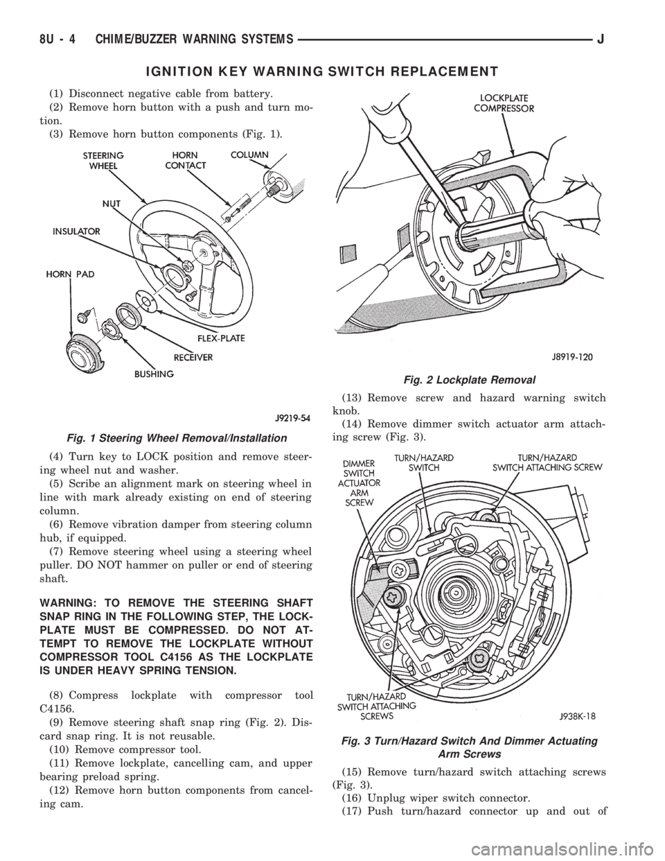
(3) Remove horn button components (Fig. 1).
(4) Turn key to LOCK position and remove steer-
ing wheel nut and washer.
(5) Scribe an alignment mark on steering wheel in
line with mark already existing on end of steering
column.
(6) Remove vibration damper from steering column
hub, if equipped.
(7) Remove steering wheel using a steering wheel
puller. DO NOT hammer on puller or end of steering
shaft.
WARNING: TO REMOVE THE STEERING SHAFT
SNAP RING IN THE FOLLOWING STEP, THE LOCK-
PLATE MUST BE COMPRESSED. DO NOT AT-
TEMPT TO REMOVE THE LOCKPLATE WITHOUT
COMPRESSOR TOOL C4156 AS THE LOCKPLATE
IS UNDER HEAVY SPRING TENSION.
(8) Compress lockplate with compressor tool
C4156.
(9) Remove steering shaft snap ring (Fig. 2). Dis-
card snap ring. It is not reusable.
(10) Remove compressor tool.
(11) Remove lockplate, cancelling cam, and upper
bearing preload spring.
(12) Remove horn button components from cancel-
ing cam.(13) Remove screw and hazard warning switch
knob.
(14) Remove dimmer switch actuator arm attach-
ing screw (Fig. 3).
(15) Remove turn/hazard switch attaching screws
(Fig. 3).
(16) Unplug wiper switch connector.
(17) Push turn/hazard connector up and out of
Fig. 1 Steering Wheel Removal/Installation
Fig. 2 Lockplate Removal
Fig. 3 Turn/Hazard Switch And Dimmer Actuating
Arm Screws
8U - 4 CHIME/BUZZER WARNING SYSTEMSJ
Page 497 of 1784
FUSIBLE LINK REPLACEMENT
CAUTION: Do not replace blown fusible links with a
standard wire. Only use fusible type wire with hypa-
lon insulation or damage to the electrical system
could occur. Also make sure correct gauge of wir-
ing is used. Refer to the wiring diagrams for proper
gauge and color.
When a fusible link blows it is important to find
out what the problem is. They are placed in the elec-
trical system for protection against shorts to ground.
This can be caused by a component failure or various
wiring failures.Do not just replace the fusible
link to correct the problem.
When diagnosing a faulty fusible link it is impor-
tant to check the wire carefully. In some instances
the link may be blown and it will not show through
the insulation, the wire should be checked over its
entire length for internal breaks.
(1) Disconnect battery negative cable.
(2) Cut out the blown portion of the fusible link.
(3) Strip 1 inch of insulation from each end of the
existing fusible link.
(4) Place a piece of heat shrink tubing over one
side of the fusible link. Make sure the tubing will be
long enough to cover and seal the entire repair area.
(5) Cut a replacement piece of fusible link approx-
imately two inches longer than the piece removed.
(6) Remove one inch of insulation from each end of
the replacement fusible link.
(7) Spread the strands of wire apart on each of the
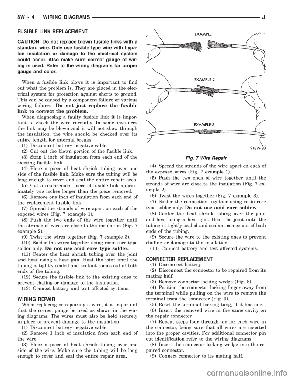
exposed wires (Fig. 7 example 1).
(8) Push the two ends of the wire together until
the strands of wire are close to the insulation (Fig. 7
example 2).
(9) Twist the wires together (Fig. 7 example 3).
(10) Solder the wires together using rosin core type
solder only.Do not use acid core type solder.
(11) Center the heat shrink tubing over the joint
and heat using a heat gun. Heat the joint until the
tubing is tightly sealed and sealant comes out of both
ends of the tubing.
(12) Secure the fusible link to the existing ones to
prevent chafing or damage to the insulation.
(13) Connect battery and test affected systems.
WIRING REPAIR
When replacing or repairing a wire, it is important
that the correct gauge be used as shown in the wir-
ing diagrams. The wires must also be held securely
in place to prevent damage to the insulation.
(1) Disconnect battery negative cable.
(2) Remove 1 inch of insulation from each end of
the wire.
(3) Place a piece of heat shrink tubing over one
side of the wire. Make sure the tubing will be long
enough to cover and seal the entire repair area.(4) Spread the strands of the wire apart on each of
the exposed wires (Fig. 7 example 1).
(5) Push the two ends of wire together until the
strands of wire are close to the insulation (Fig. 7 ex-
ample 2).
(6) Twist the wires together (Fig. 7 example 3).
(7) Solder the connection together using rosin core
type solder only.Do not use acid core solder.
(8) Center the heat shrink tubing over the joint
and heat using a heat gun. Heat the joint until the
tubing is tightly sealed and sealant comes out of both
ends of the tubing.
(9) Secure the wire to the existing ones to prevent
chafing or damage to the insulation.
(10) Connect battery and test affected systems.
CONNECTOR REPLACEMENT
(1) Disconnect battery.
(2) Disconnect the connector to be repaired from its
mating half.
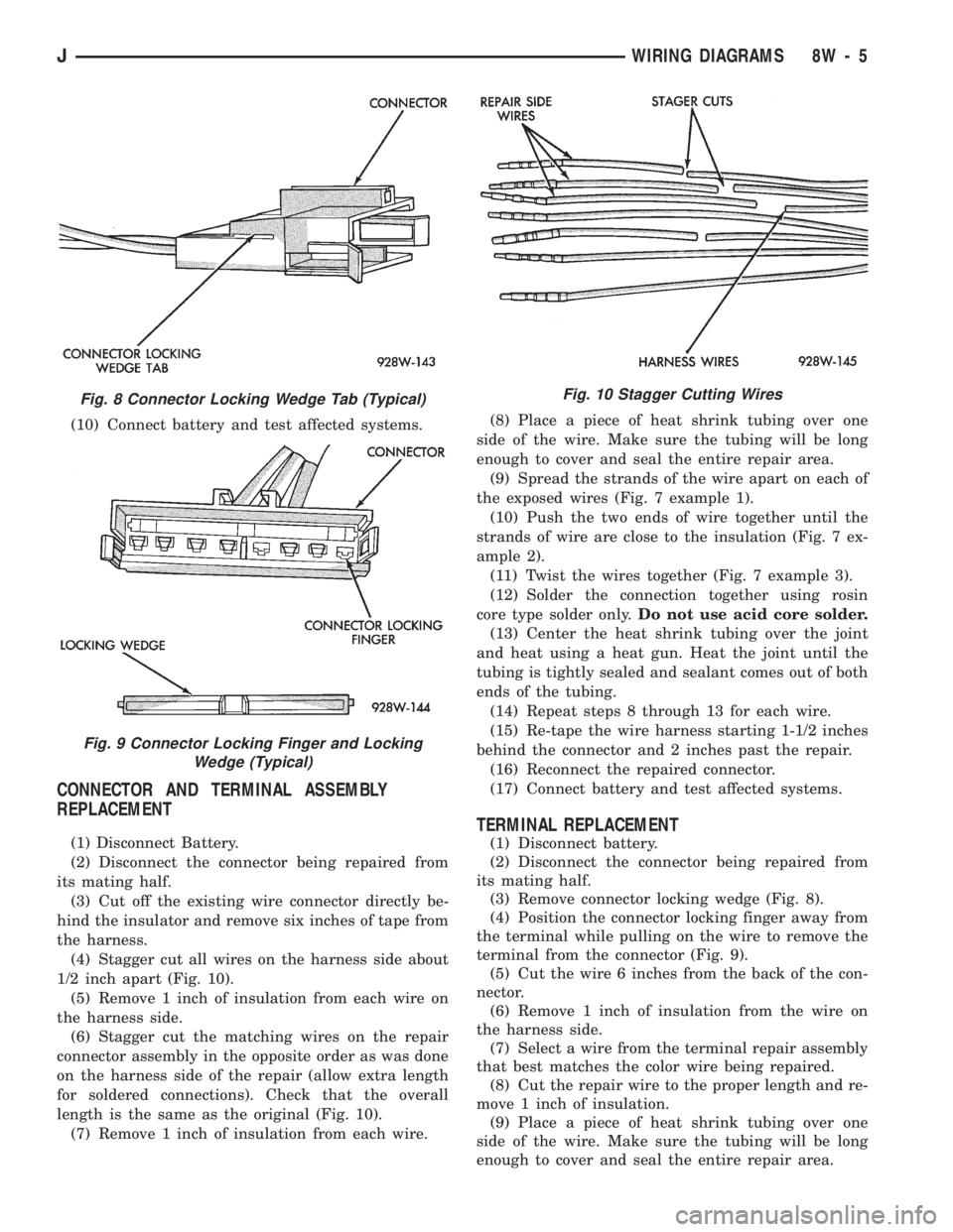
(3) Remove connector locking wedge (Fig. 8).
(4) Position the connector locking finger away from
the terminal while pulling on the wire to remove the
terminal from the connector (Fig. 9).
(5) Reset the terminal locking tang, if it has one.
(6) Insert the removed wire in the same cavity on
the repair connector.
(7) Repeat steps four through six for each wire in
the connector, being sure that all wires are inserted
into the proper cavities. For additional connector pin
out identification refer to the wiring diagrams.
(8) Insert the connector locking wedge into the re-
paired connector.
(9) Connect connector to its mating half.
Fig. 7 Wire Repair
8W - 4 WIRING DIAGRAMSJ
Page 498 of 1784
(10) Connect battery and test affected systems.
CONNECTOR AND TERMINAL ASSEMBLY
REPLACEMENT
(1) Disconnect Battery.
(2) Disconnect the connector being repaired from
its mating half.
(3) Cut off the existing wire connector directly be-
hind the insulator and remove six inches of tape from
the harness.
(4) Stagger cut all wires on the harness side about
1/2 inch apart (Fig. 10).
(5) Remove 1 inch of insulation from each wire on
the harness side.
(6) Stagger cut the matching wires on the repair
connector assembly in the opposite order as was done
on the harness side of the repair (allow extra length
for soldered connections). Check that the overall
length is the same as the original (Fig. 10).
(7) Remove 1 inch of insulation from each wire.(8) Place a piece of heat shrink tubing over one
side of the wire. Make sure the tubing will be long
enough to cover and seal the entire repair area.
(9) Spread the strands of the wire apart on each of
the exposed wires (Fig. 7 example 1).
(10) Push the two ends of wire together until the
strands of wire are close to the insulation (Fig. 7 ex-
ample 2).
(11) Twist the wires together (Fig. 7 example 3).
(12) Solder the connection together using rosin
core type solder only.Do not use acid core solder.
(13) Center the heat shrink tubing over the joint
and heat using a heat gun. Heat the joint until the
tubing is tightly sealed and sealant comes out of both
ends of the tubing.
(14) Repeat steps 8 through 13 for each wire.
(15) Re-tape the wire harness starting 1-1/2 inches
behind the connector and 2 inches past the repair.
(16) Reconnect the repaired connector.
(17) Connect battery and test affected systems.
TERMINAL REPLACEMENT
(1) Disconnect battery.
(2) Disconnect the connector being repaired from
its mating half.
(3) Remove connector locking wedge (Fig. 8).
(4) Position the connector locking finger away from
the terminal while pulling on the wire to remove the
terminal from the connector (Fig. 9).
(5) Cut the wire 6 inches from the back of the con-
nector.
(6) Remove 1 inch of insulation from the wire on
the harness side.
(7) Select a wire from the terminal repair assembly
that best matches the color wire being repaired.
(8) Cut the repair wire to the proper length and re-
move 1 inch of insulation.
(9) Place a piece of heat shrink tubing over one
side of the wire. Make sure the tubing will be long
enough to cover and seal the entire repair area.
Fig. 8 Connector Locking Wedge Tab (Typical)
Fig. 9 Connector Locking Finger and Locking
Wedge (Typical)
Fig. 10 Stagger Cutting Wires
JWIRING DIAGRAMS 8W - 5
Page 499 of 1784

(10) Spread the strands of the wire apart on each
of the exposed wires (Fig. 7 example 1).
(11) Push the two ends of wire together until the
strands of wire are close to the insulation (Fig. 7 ex-
ample 2).
(12) Twist the wires together (Fig. 7 example 3).
(13) Solder the connection together using rosin
core type solder only.Do not use acid core solder.
(14) Center the heat shrink tubing over the joint
and heat using a heat gun. Heat the joint until the
tubing is tightly sealed and sealant comes out of both
ends of the tubing.
(15) Insert the repaired wire into the connector.
(16) Install the connector locking wedge and recon-
nect the connector to its mating half.
(17) Re-tape the wire harness starting 1-1/2 inches
behind the connector and 2 inches past the repair.(18) Connect battery and test affected systems.
SYMBOLS, FUSES AND ABBREVIATIONS
Various symbols are used throughout the wiring di-
agrams. These symbols can be identified by referring
to the symbol identification chart (Fig. 11).
Certain abbreviations are also used in the dia-
grams. These have been developed in such a way
that there meaning should be clear. For fuse block,
relay bank, and power distribution center informa-
tion refer to the fuse charts and relay bank index.
CAUTION: When replacing a blown fuse it is impor-
tant to replace it with a fuse having the correct am-
perage rating. The use of a fuse with a rating other
than indicated may result in an electrical overload.
If a proper rated fuse continues to blow, it indicates
a problem that should be corrected.
8W - 6 WIRING DIAGRAMSJ
Page 506 of 1784
WIRING AND COMPONENT IDENTIFICATION
CONTENTS
page page
XJ ................................... 25
XJ RHD ............................... 43YJ ................................... 13
The wiring and components shown in this section
are divided into sections by vehicle line. When locat-
ing a specific wire routing or component, first turn to
the appropriate index, then look up thefigure num-
berthat refers to the component.Page numbers at
the top of the page do not refer to figure num-
bers.
YJ
Caption Fig.
Battery and Starter Wiring.......................8
Body Wiring...............................1,2
Chassis Wiring...............................3
Engine Compartment Wiring......................7
Engine Wiring 2.5L...........................10Caption Fig.
Engine Wiring 4.0L...........................11
Front End Wiring.............................12
Instrument Panel Wiring.......................5,6
Steering Column Wiring.........................4
Transmission Wiring...........................9
JWIRING AND COMPONENT IDENTIFICATION 8W - 13