1994 JEEP CHEROKEE wiring
[x] Cancel search: wiringPage 766 of 1784
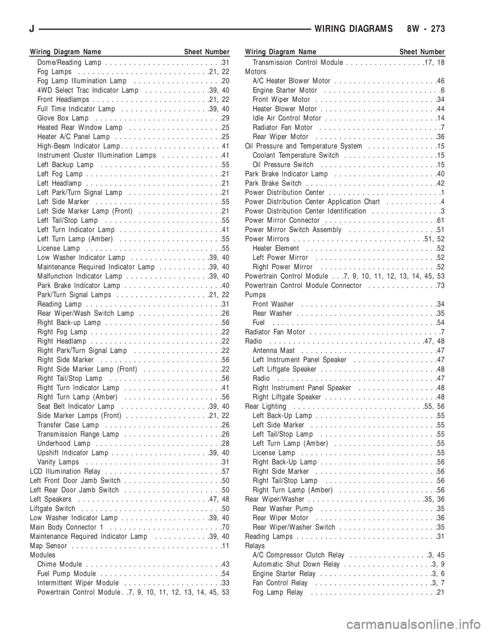
Wiring Diagram Name Sheet Number
Dome/Reading Lamp.........................31
Fog Lamps............................21, 22
Fog Lamp Illumination Lamp...................20
4WD Select Trac Indicator Lamp..............39, 40
Front Headlamps.........................21, 22
Full Time Indicator Lamp...................39, 40
Glove Box Lamp...........................29
Heated Rear Window Lamp....................25
Heater A/C Panel Lamp.......................25
High-Beam Indicator Lamp.....................41
Instrument Cluster Illumination Lamps.............41
Left Backup Lamp..........................55
Left Fog Lamp.............................21
Left Headlamp.............................21
Left Park/Turn Signal Lamp....................21
Left Side Marker...........................55
Left Side Marker Lamp (Front)..................21
Left Tail/Stop Lamp.........................55
Left Turn Indicator Lamp......................41
Left Turn Lamp (Amber)......................55
License Lamp.............................55
Low Washer Indicator Lamp.................39, 40
Maintenance Required Indicator Lamp...........39, 40
Malfunction Indicator Lamp..................39, 40
Park Brake Indicator Lamp.....................40
Park/Turn Signal Lamps....................21, 22
Reading Lamp.............................31
Rear Wiper/Wash Switch Lamp..................26
Right Back-up Lamp.........................56
Right Fog Lamp............................22
Right Headlamp............................22
Right Park/Turn Signal Lamp...................22
Right Side Marker..........................56
Right Side Marker Lamp (Front).................22
Right Tail/Stop Lamp........................56
Right Turn Indicator Lamp.....................41
Right Turn Lamp (Amber).....................56
Seat Belt Indicator Lamp...................39, 40
Side Marker Lamps (Front)..................21, 22
Transfer Case Lamp.........................26
Transmission Range Lamp.....................26
Underhood Lamp...........................28
Upshift Indicator Lamp.....................39, 40
Vanity Lamps.............................31
LCD Illumination Relay.........................57
Left Front Door Jamb Switch.....................50
Left Rear Door Jamb Switch.....................50
Left Speakers............................47, 48
Liftgate Switch..............................50
Low Washer Indicator Lamp...................39, 40
Main Body Connector 1........................70
Maintenance Required Indicator Lamp............39, 40
Map Sensor................................11
Modules
Chime Module.............................43
Fuel Pump Module..........................54
Intermittent Wiper Module.....................33
Powertrain Control Module . .7, 9, 10, 11, 12, 13, 14, 45, 53Wiring Diagram Name Sheet Number
Transmission Control Module.................17, 18
Motors
A/C Heater Blower Motor......................46
Engine Starter Motor.........................6
Front Wiper Motor..........................34
Heater Blower Motor.........................44
Idle Air Control Motor........................14
Radiator Fan Motor..........................7
Rear Wiper Motor..........................36
Oil Pressure and Temperature System...............15
Coolant Temperature Switch....................15
Oil Pressure Switch.........................15
Park Brake Indicator Lamp......................40
Park Brake Switch............................42
Power Distribution Center........................1
Power Distribution Center Application Chart............4
Power Distribution Center Identification...............3
Power Mirror Connector........................61
Power Mirror Switch Assembly...................51
Power Mirrors............................51, 52
Heater Element............................52
Left Power Mirror..........................52
Right Power Mirror.........................52
Powertrain Control Module . . .7, 9, 10, 11, 12, 13, 14, 45, 53
Powertrain Control Module Connector...............73
Pumps
Front Washer.............................34
Rear Washer..............................35
Fuel...................................54
Radiator Fan Motor............................7
Radio.................................47, 48
Antenna Mast.............................47
Left Instrument Panel Speaker..................47
Left Liftgate Speaker.........................48
Radio..................................47
Right Instrument Panel Speaker.................48
Right Liftgate Speaker........................48
Rear Lighting............................55, 56
Left Back-Up Lamp..........................55
Left Side Marker...........................55
Left Tail/Stop Lamp.........................55
Left Turn Lamp (Amber)......................55
License Lamp.............................55
Right Back-Up Lamp.........................56
Right Side Marker..........................56
Right Tail/Stop Lamp........................56
Right Turn Lamp (Amber).....................56
Rear Wiper/Washer.........................35, 36
Rear Washer Pump.........................35
Rear Wiper Motor..........................36
Rear Wiper/Washer Switch.....................35
Reading Lamps..............................31
Relays
A/C Compressor Clutch Relay.................3,45
Automatic Shut Down Relay...................3,9
Engine Starter Relay........................3,6
Fan Control Relay.........................3,7
Fog Lamp Relay...........................21
JWIRING DIAGRAMS 8W - 273
Page 767 of 1784
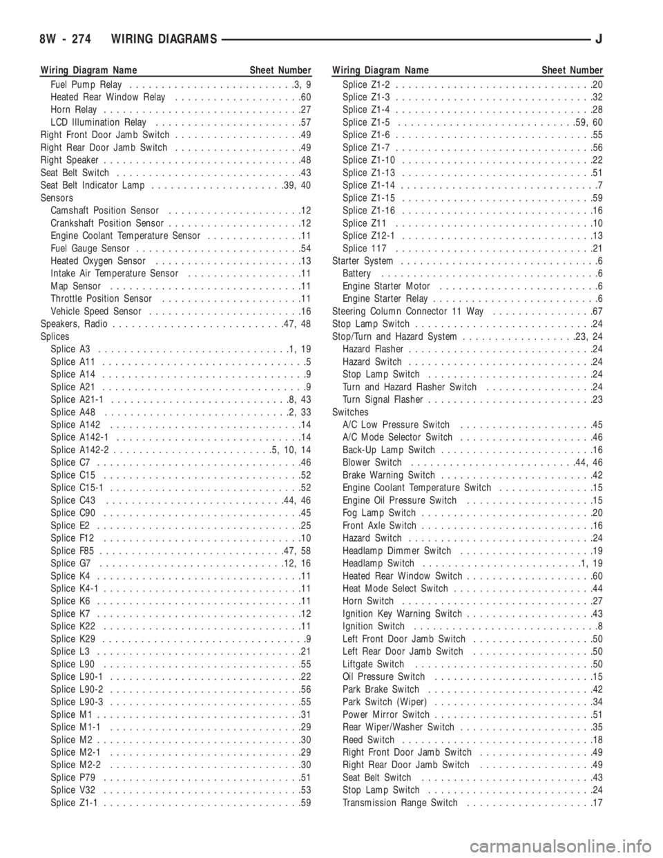
Wiring Diagram Name Sheet Number
Fuel Pump Relay..........................3,9
Heated Rear Window Relay....................60
Horn Relay...............................27
LCD Illumination Relay.......................57
Right Front Door Jamb Switch....................49
Right Rear Door Jamb Switch....................49
Right Speaker...............................48
Seat Belt Switch.............................43
Seat Belt Indicator Lamp.....................39, 40
Sensors
Camshaft Position Sensor.....................12
Crankshaft Position Sensor.....................12
Engine Coolant Temperature Sensor...............11
Fuel Gauge Sensor..........................54
Heated Oxygen Sensor.......................13
Intake Air Temperature Sensor..................11
Map Sensor..............................11
Throttle Position Sensor......................11
Vehicle Speed Sensor........................16
Speakers, Radio...........................47, 48
Splices
Splice A3..............................1,19
Splice A11................................5
Splice A14................................9
Splice A21................................9
Splice A21-1............................8,43
Splice A48.............................2,33
Splice A142..............................14
Splice A142-1.............................14
Splice A142-2.........................5,10,14
Splice C7................................46
Splice C15...............................52
Splice C15-1..............................52
Splice C43............................44, 46
Splice C90...............................45
Splice E2................................25
Splice F12...............................10
Splice F85.............................47, 58
Splice G7.............................12, 16
Splice K4................................11
Splice K4-1...............................11
Splice K6................................11
Splice K7................................12
Splice K22...............................11
Splice K29................................9
Splice L3................................21
Splice L90...............................55
Splice L90-1..............................22
Splice L90-2..............................56
Splice L90-3..............................55
Splice M1................................31
Splice M1-1..............................29
Splice M2................................30
Splice M2-1..............................29
Splice M2-2..............................30
Splice P79...............................51
Splice V32...............................53
Splice Z1-1...............................59Wiring Diagram Name Sheet Number
Splice Z1-2...............................20
Splice Z1-3...............................32
Splice Z1-4...............................28
Splice Z1-5............................59, 60
Splice Z1-6...............................55
Splice Z1-7...............................56
Splice Z1-10..............................22
Splice Z1-13..............................51
Splice Z1-14...............................7
Splice Z1-15..............................59
Splice Z1-16..............................16
Splice Z11...............................10
Splice Z12-1..............................13
Splice 117...............................21
Starter System...............................6
Battery..................................6
Engine Starter Motor.........................6
Engine Starter Relay..........................6
Steering Column Connector 11 Way................67
Stop Lamp Switch............................24
Stop/Turn and Hazard System..................23, 24
Hazard Flasher.............................24
Hazard Switch.............................24
Stop Lamp Switch..........................24
Turn and Hazard Flasher Switch.................24
Turn Signal Flasher..........................23
Switches
A/C Low Pressure Switch.....................45
A/C Mode Selector Switch.....................46
Back-Up Lamp Switch........................16
Blower Switch..........................44, 46
Brake Warning Switch........................42
Engine Coolant Temperature Switch...............15
Engine Oil Pressure Switch....................15
Fog Lamp Switch...........................20
Front Axle Switch...........................16
Hazard Switch.............................24
Headlamp Dimmer Switch.....................19
Headlamp Switch.........................1,19
Heated Rear Window Switch....................60
Heat Mode Select Switch......................44
Horn Switch..............................27
Ignition Key Warning Switch....................43
Ignition Switch.............................8
Left Front Door Jamb Switch...................50
Left Rear Door Jamb Switch...................50
Liftgate Switch............................50
Oil Pressure Switch.........................15
Park Brake Switch..........................42
Park Switch (Wiper).........................34
Power Mirror Switch.........................51
Rear Wiper/Washer Switch.....................35
Reed Switch..............................18
Right Front Door Jamb Switch..................49
Right Rear Door Jamb Switch..................49
Seat Belt Switch...........................43
Stop Lamp Switch..........................24
Transmission Range Switch....................17
8W - 274 WIRING DIAGRAMSJ
Page 768 of 1784
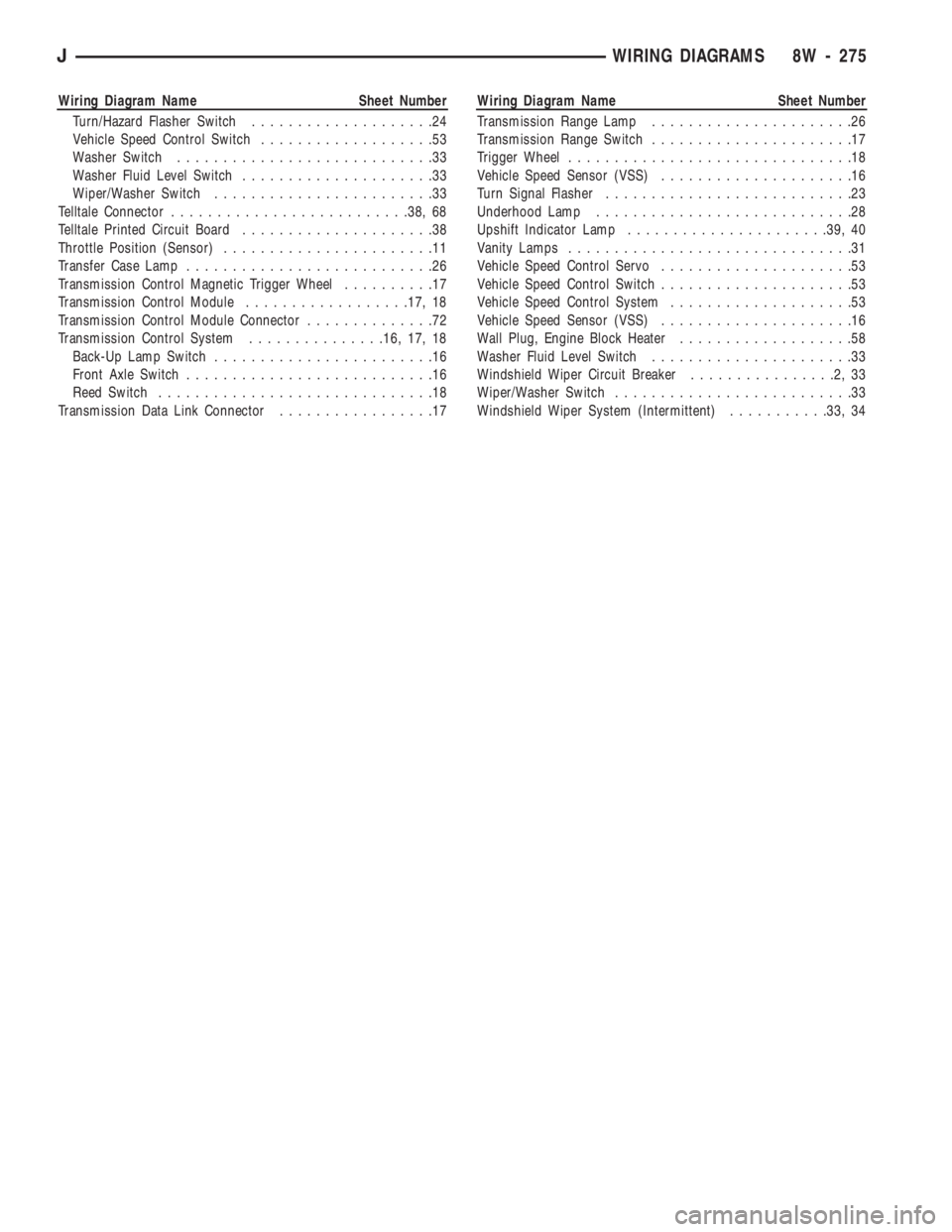
Wiring Diagram Name Sheet Number
Turn/Hazard Flasher Switch....................24
Vehicle Speed Control Switch...................53
Washer Switch............................33
Washer Fluid Level Switch.....................33
Wiper/Washer Switch........................33
Telltale Connector..........................38, 68
Telltale Printed Circuit Board.....................38
Throttle Position (Sensor).......................11
Transfer Case Lamp...........................26
Transmission Control Magnetic Trigger Wheel..........17
Transmission Control Module..................17, 18
Transmission Control Module Connector..............72
Transmission Control System...............16, 17, 18
Back-Up Lamp Switch........................16
Front Axle Switch...........................16
Reed Switch..............................18
Transmission Data Link Connector.................17Wiring Diagram Name Sheet Number
Transmission Range Lamp......................26
Transmission Range Switch......................17
Trigger Wheel...............................18
Vehicle Speed Sensor (VSS).....................16
Turn Signal Flasher...........................23
Underhood Lamp............................28
Upshift Indicator Lamp......................39, 40
Vanity Lamps...............................31
Vehicle Speed Control Servo.....................53
Vehicle Speed Control Switch.....................53
Vehicle Speed Control System....................53
Vehicle Speed Sensor (VSS).....................16
Wall Plug, Engine Block Heater...................58
Washer Fluid Level Switch......................33
Windshield Wiper Circuit Breaker................2,33
Wiper/Washer Switch..........................33
Windshield Wiper System (Intermittent)...........33, 34
JWIRING DIAGRAMS 8W - 275
Page 982 of 1784
Refer to Group 8D, Ignition System for more crank-
shaft position sensor information.
The engine will not operate if the PCM does not re-
ceive a crankshaft position sensor input.
ENGINE COOLANT TEMPERATURE SENSORÐPCM
INPUT
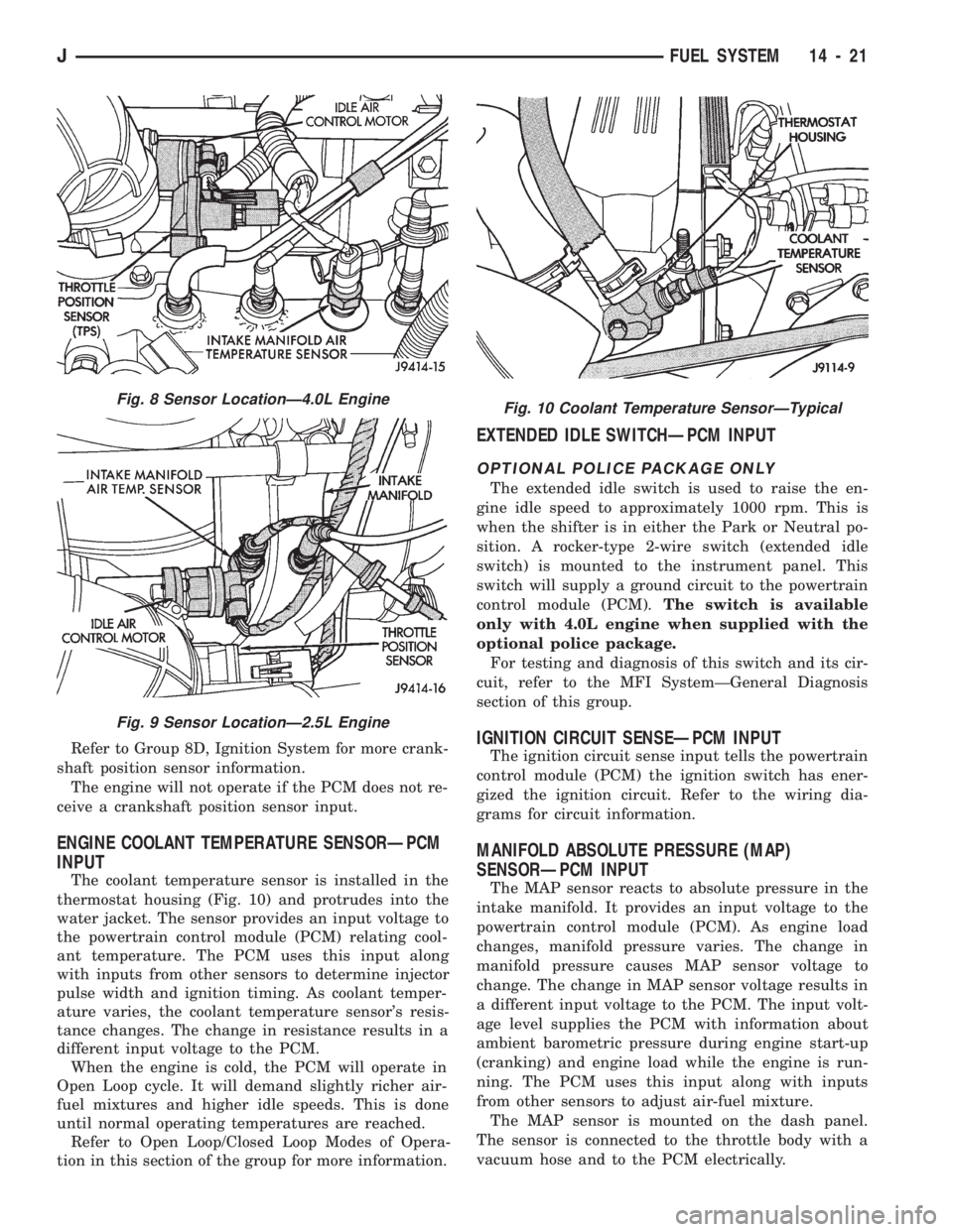
The coolant temperature sensor is installed in the
thermostat housing (Fig. 10) and protrudes into the
water jacket. The sensor provides an input voltage to
the powertrain control module (PCM) relating cool-
ant temperature. The PCM uses this input along
with inputs from other sensors to determine injector
pulse width and ignition timing. As coolant temper-
ature varies, the coolant temperature sensor's resis-
tance changes. The change in resistance results in a
different input voltage to the PCM.
When the engine is cold, the PCM will operate in
Open Loop cycle. It will demand slightly richer air-
fuel mixtures and higher idle speeds. This is done
until normal operating temperatures are reached.
Refer to Open Loop/Closed Loop Modes of Opera-
tion in this section of the group for more information.
EXTENDED IDLE SWITCHÐPCM INPUT
OPTIONAL POLICE PACKAGE ONLY
The extended idle switch is used to raise the en-
gine idle speed to approximately 1000 rpm. This is
when the shifter is in either the Park or Neutral po-
sition. A rocker-type 2-wire switch (extended idle
switch) is mounted to the instrument panel. This
switch will supply a ground circuit to the powertrain
control module (PCM).The switch is available
only with 4.0L engine when supplied with the
optional police package.
For testing and diagnosis of this switch and its cir-
cuit, refer to the MFI SystemÐGeneral Diagnosis
section of this group.
IGNITION CIRCUIT SENSEÐPCM INPUT
The ignition circuit sense input tells the powertrain
control module (PCM) the ignition switch has ener-
gized the ignition circuit. Refer to the wiring dia-
grams for circuit information.
MANIFOLD ABSOLUTE PRESSURE (MAP)
SENSORÐPCM INPUT
The MAP sensor reacts to absolute pressure in the
intake manifold. It provides an input voltage to the
powertrain control module (PCM). As engine load
changes, manifold pressure varies. The change in
manifold pressure causes MAP sensor voltage to
change. The change in MAP sensor voltage results in
a different input voltage to the PCM. The input volt-
age level supplies the PCM with information about
ambient barometric pressure during engine start-up
(cranking) and engine load while the engine is run-
ning. The PCM uses this input along with inputs
from other sensors to adjust air-fuel mixture.
The MAP sensor is mounted on the dash panel.
The sensor is connected to the throttle body with a
vacuum hose and to the PCM electrically.
Fig. 8 Sensor LocationÐ4.0L Engine
Fig. 9 Sensor LocationÐ2.5L Engine
Fig. 10 Coolant Temperature SensorÐTypical
JFUEL SYSTEM 14 - 21
Page 986 of 1784
FUEL PUMP RELAYÐPCM OUTPUT
The PCM energizes the fuel pump through the fuel
pump relay. Battery voltage is applied to the relay
from the ignition switch. The relay is energized when
a ground is provided by the PCM. Refer to Automatic
Shut Down Relay for additional information.
FUEL INJECTORSÐPCM OUTPUT
Six individual fuel injectors are used with the 4.0L
6 cylinder engine. Four individual fuel injectors are
used with the 2.5L 4 cylinder engine. The injectors
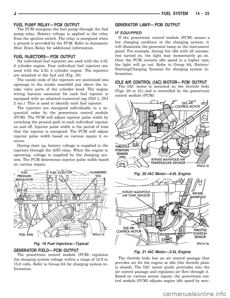
are attached to the fuel rail (Fig. 19).
The nozzle ends of the injectors are positioned into
openings in the intake manifold just above the in-
take valve ports of the cylinder head. The engine
wiring harness connector for each fuel injector is
equipped with an attached numerical tag (INJ 1, INJ
2 etc.). This is used to identify each fuel injector.
The injectors are energized individually in a se-
quential order by the powertrain control module
(PCM). The PCM will adjust injector pulse width by
switching the ground path to each individual injector
on and off. Injector pulse width is the period of time
that the injector is energized. The PCM will adjust
injector pulse width based on various inputs it re-
ceives.
During start up, battery voltage is supplied to the
injectors through the ASD relay. When the engine is
operating, voltage is supplied by the charging sys-
tem. The PCM determines injector pulse width based
on various inputs.
GENERATOR FIELDÐPCM OUTPUT
The powertrain control module (PCM) regulates
the charging system voltage within a range of 12.9 to
15.0 volts. Refer to Group 8A for charging system in-
formation.
GENERATOR LAMPÐPCM OUTPUT
IF EQUIPPED
If the powertrain control module (PCM) senses a
low charging condition in the charging system, it
will illuminate the generator lamp on the instrument
panel. For example, during low idle with all accesso-
ries turned on, the light may momentarily go on.
Once the PCM corrects idle speed to a higher rpm,
the light will go out. Refer to Group 8A, Battery/
Starting/Charging Systems for charging system in-
formation.
IDLE AIR CONTROL (IAC) MOTORÐPCM OUTPUT
The IAC motor is mounted on the throttle body
(Figs. 20 or 21) and is controlled by the powertrain
control module (PCM).
The throttle body has an air control passage that
provides air for the engine at idle (the throttle plate
is closed). The IAC motor pintle protrudes into the
air control passage and regulates air flow through it.
Based on various sensor inputs, the powertrain con-
trol module (PCM) adjusts engine idle speed by mov-
Fig. 19 Fuel InjectorsÐTypical
Fig. 20 IAC MotorÐ4.0L Engine
Fig. 21 IAC MotorÐ2.5L Engine
JFUEL SYSTEM 14 - 25
Page 994 of 1784
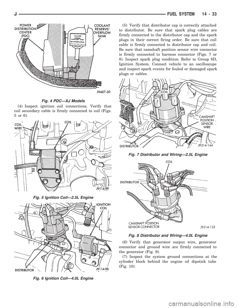
(4) Inspect ignition coil connections. Verify that
coil secondary cable is firmly connected to coil (Figs.
5or6).(5) Verify that distributor cap is correctly attached
to distributor. Be sure that spark plug cables are
firmly connected to the distributor cap and the spark
plugs in their correct firing order. Be sure that coil
cable is firmly connected to distributor cap and coil.
Be sure that camshaft position sensor wire connector
is firmly connected to harness connector (Figs. 7 or
8). Inspect spark plug condition. Refer to Group 8D,
Ignition System. Connect vehicle to an oscilloscope
and inspect spark events for fouled or damaged spark
plugs or cables.
(6) Verify that generator output wire, generator
connector and ground wire are firmly connected to
the generator (Fig. 9).
(7) Inspect the system ground connections at the
cylinder block behind the engine oil dipstick tube
(Fig. 10).
Fig. 4 PDCÐXJ Models
Fig. 5 Ignition CoilÐ2.5L Engine
Fig. 6 Ignition CoilÐ4.0L Engine
Fig. 7 Distributor and WiringÐ2.5L Engine
Fig. 8 Distributor and WiringÐ4.0L Engine
JFUEL SYSTEM 14 - 33
Page 999 of 1784
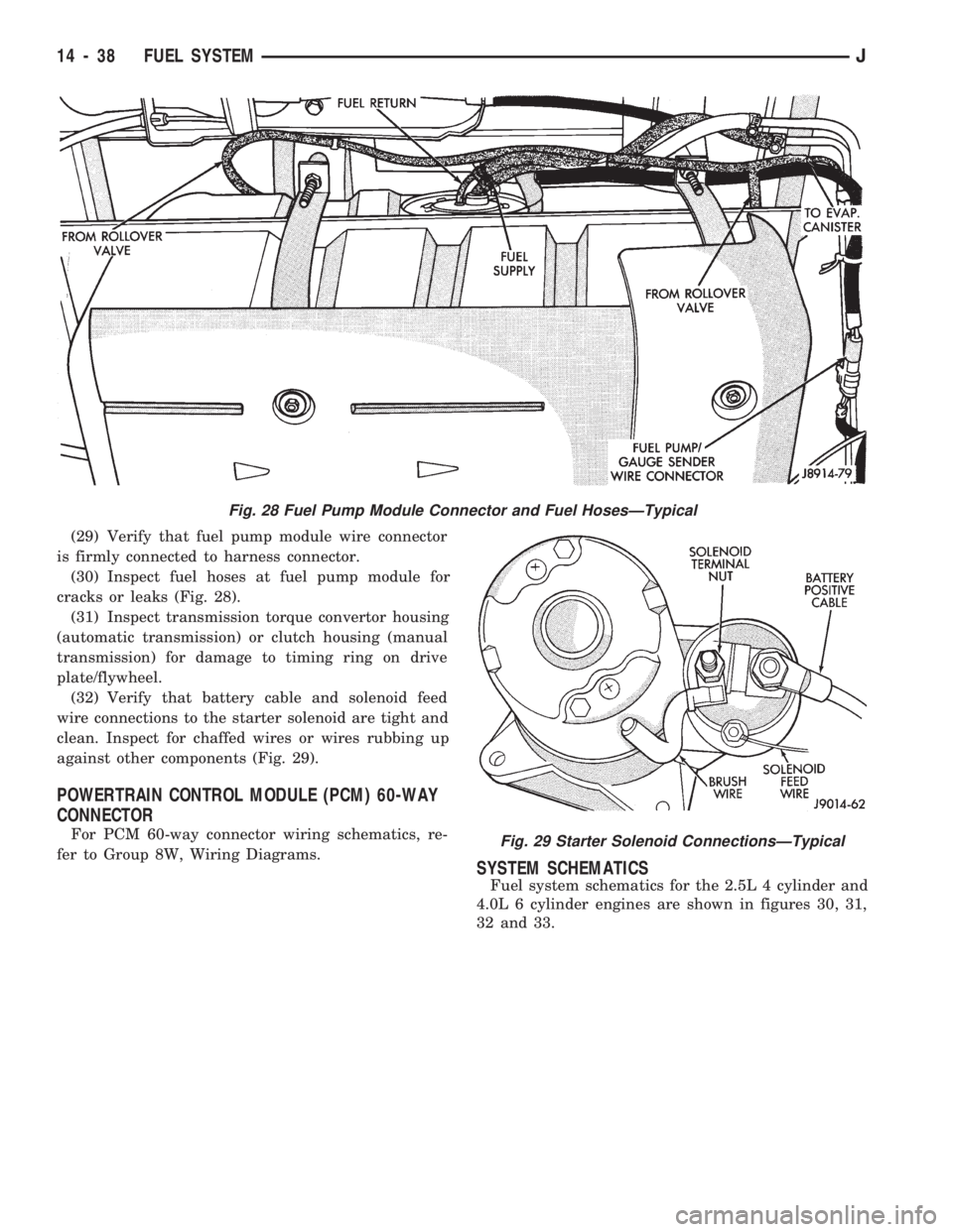
(29) Verify that fuel pump module wire connector
is firmly connected to harness connector.
(30) Inspect fuel hoses at fuel pump module for
cracks or leaks (Fig. 28).
(31) Inspect transmission torque convertor housing
(automatic transmission) or clutch housing (manual
transmission) for damage to timing ring on drive
plate/flywheel.
(32) Verify that battery cable and solenoid feed
wire connections to the starter solenoid are tight and
clean. Inspect for chaffed wires or wires rubbing up
against other components (Fig. 29).
POWERTRAIN CONTROL MODULE (PCM) 60-WAY
CONNECTOR
For PCM 60-way connector wiring schematics, re-
fer to Group 8W, Wiring Diagrams.
SYSTEM SCHEMATICS
Fuel system schematics for the 2.5L 4 cylinder and
4.0L 6 cylinder engines are shown in figures 30, 31,
32 and 33.
Fig. 28 Fuel Pump Module Connector and Fuel HosesÐTypical
Fig. 29 Starter Solenoid ConnectionsÐTypical
14 - 38 FUEL SYSTEMJ
Page 1005 of 1784
harness connector terminal-2 and the sensor connec-
tor terminal. Also test terminal-4 to the sensor con-
nector terminal. Repair the wire harness as
necessary if the resistance is greater than 1 ohm.
FUEL PUMP RELAY TESTING
For testing this relay, refer to RelaysÐOperation/
Testing in this section of the group.
MANIFOLD ABSOLUTE PRESSURE (MAP) SENSOR
TEST
To perform a complete test of the MAP sensor and
its circuitry, refer to DRB scan tool and appropriate
Powertrain Diagnostics Procedures manual. To test
the sensor only, refer to the following:
Inspect the MAP sensor vacuum hose connections
at the throttle body and sensor. Repair as necessary.
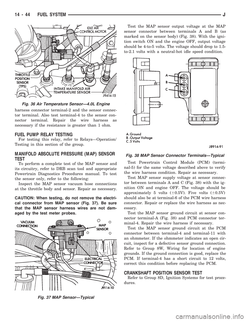
CAUTION: When testing, do not remove the electri-
cal connector from MAP sensor (Fig. 37). Be sure
that the MAP sensor harness wires are not dam-
aged by the test meter probes.Test the MAP sensor output voltage at the MAP
sensor connector between terminals A and B (as
marked on the sensor body) (Fig. 38). With the igni-
tion switch ON and the engine OFF, output voltage
should be 4-to-5 volts. The voltage should drop to 1.5-
to-2.1 volts with a neutral-hot idle speed condition.
Test Powertrain Control Module (PCM) (termi-
nal-5) for the same voltage described above to verify
the wire harness condition. Repair as necessary.
Test MAP sensor supply voltage at sensor connec-
tor between terminals A and C (Fig. 38) with the ig-
nition ON and engine OFF. The voltage should be
approximately 5 volts (60.5V). Five volts (60.5V)
should also be at terminal-6 of the PCM wire harness
connector. Repair or replace the wire harness as nec-
essary.
Test the MAP sensor ground circuit at sensor con-
nector terminal-A (Fig. 38) and PCM connector ter-
minal-4. Repair the wire harness if necessary.
Test the MAP sensor ground circuit at the PCM
connector between terminal-4 and terminal-11 with
an ohmmeter. If the ohmmeter indicates an open cir-
cuit, inspect for a defective sensor ground connection.
Refer to Group 8W, Wiring for location of engine
grounds. If the ground connection is good, replace the
PCM. If terminal-4 has a short circuit to 12 volts,
correct this condition before replacing the PCM.
CRANKSHAFT POSITION SENSOR TEST
Refer to Group 8D, Ignition Systems for test proce-
dures.
Fig. 36 Air Temperature SensorÐ4.0L Engine
Fig. 37 MAP SensorÐTypical
Fig. 38 MAP Sensor Connector TerminalsÐTypical
14 - 44 FUEL SYSTEMJ