1994 JEEP CHEROKEE wiring
[x] Cancel search: wiringPage 1006 of 1784
EXTENDED IDLE SWITCH TEST
OPTIONAL POLICE PACKAGE ONLY
OPERATION
The extended idle switch is used to raise the en-
gine idle speed to approximately 1000 rpm when the
shifter is in either the Park or Neutral position. A
rocker-type 2-wire switch (extended idle switch) is
mounted to the instrument panel.This switch is
available only with 4.0L engine when supplied
with the optional police package.
TESTING
The extended idle switch will control a ground cir-
cuit going to the powertrain control module (PCM).
When a ground signal (through this switch) has been
received at pin number 10 in the PCM, engine idle
speed will increase.
Bring the engine to normal operating temperature
and turn the extended idle switch to the ON position.
Engine speed should now increase to approximately
1000 rpm when the shifter is in either the Park or
Neutral position. If engine speed does not increase,
apply a good ground to pin number 10 at the PCM
using a small paper clip. Be careful not to damage
the wiring with the paper clip. If the engine speed
now increases, it can be assumed that the PCM is
functioning correctly. Check the instrument panel
mounted switch for a closed ground circuit when in
the ON position. If the engine speed will not increase
after applying a ground to pin number 10, replace
the PCM. Refer to Group 8W, Wiring Diagrams for
circuit and wiring information.
THROTTLE POSITION SENSOR (TPS) TEST
To perform a complete test of the sensor and its cir-
cuitry, refer to DRB scan tool and appropriate Pow-
ertrain Diagnostics Procedures manual. To test the
sensor only, refer to the following:
The throttle position sensor (TPS) can be tested
with a digital voltmeter. The center terminal of the
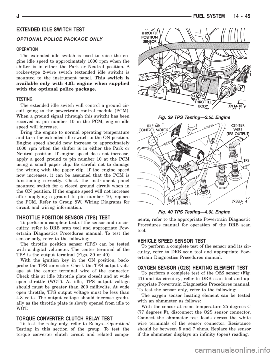
TPS is the output terminal (Figs. 39 or 40).
With the ignition key in the ON position, back-
probe the TPS connector. Check the TPS output volt-
age at the center terminal wire of the connector.
Check this at idle (throttle plate closed) and at wide
open throttle (WOT). At idle, TPS output voltage
should must be greater than 200 millivolts. At wide
open throttle, TPS output voltage must be less than
4.8 volts. The output voltage should increase gradu-
ally as the throttle plate is slowly opened from idle to
WOT.
TORQUE CONVERTER CLUTCH RELAY TEST
To test the relay only, refer to RelaysÐOperation/
Testing in this section of the group. To test the
torque converter clutch circuit and related compo-nents, refer to the appropriate Powertrain Diagnostic
Procedures manual for operation of the DRB scan
tool.
VEHICLE SPEED SENSOR TEST
To perform a complete test of the sensor and its cir-
cuitry, refer to DRB scan tool and appropriate Pow-
ertrain Diagnostics Procedures manual.
OXYGEN SENSOR (O2S) HEATING ELEMENT TEST
To perform a complete test of the O2S sensor (Fig.
41) and its circuitry, refer to DRB scan tool and ap-
propriate Powertrain Diagnostics Procedures manual.
To test the sensor only, refer to the following:
The oxygen sensor heating element can be tested
with an ohmmeter as follows:
With the sensor at room temperature 25 degrees C
(77 degrees F), disconnect the O2S sensor connector.
Connect the ohmmeter test leads across the white
wire terminals of the sensor connector. Resistance
should be between 5 and 7 ohms. Replace the sensor
if the ohmmeter displays an infinity (open) reading.
Fig. 39 TPS TestingÐ2.5L Engine
Fig. 40 TPS TestingÐ4.0L Engine
JFUEL SYSTEM 14 - 45
Page 1214 of 1784
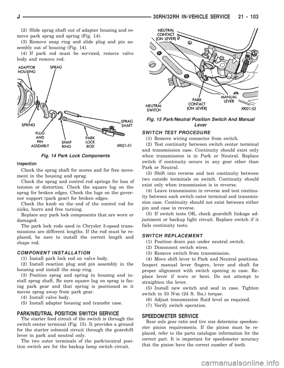
(2) Slide sprag shaft out of adapter housing and re-
move park sprag and spring (Fig. 14).
(3) Remove snap ring and slide plug and pin as-
sembly out of housing (Fig. 14).
(4) If park rod must be serviced, remove valve
body and remove rod.
Inspection
Check the sprag shaft for scores and for free move-
ment in the housing and sprag.
Check the sprag and control rod springs for loss of
tension or distortion. Check the square lug on the
sprag for broken edges. Check the lugs on the gover-
nor support (park gear) for broken edges.
Check the knob on the end of the control rod for
nicks, burrs and free turning.
Replace any park lock components that are worn or
damaged.
The park lock rods used in Chrysler 3-speed trans-
missions are different lengths. If the rod must be re-
placed, be sure to install the correct length and
shape rod.
COMPONENT INSTALLATION
(1) Install park lock rod on valve body.
(2) Install reaction plug and pin assembly in the
housing and install the snap ring.
(3) Position sprag and spring in housing and in-
stall sprag shaft. Be sure square lug on sprag is fac-
ing park gear and that spring is positioned so it
moves sprag away from park gear.
(4) Install valve body.
(5) Install adapter housing and transfer case.
PARK/NEUTRAL POSITION SWITCH SERVICE
The starter feed circuit of the switch is through the
switch center terminal (Fig. 15). It provides a ground
for the starter solenoid circuit through the gearshift
lever in park and neutral only.
The two outer terminals of the park/neutral posi-
tion switch are for the backup lamp switch circuit.
SWITCH TEST PROCEDURE
(1) Remove wiring connector from switch.
(2) Test continuity between switch center terminal
and transmission case. Continuity should exist only
when transmission is in Park or Neutral. Replace
switch if continuity occurs in any gear other than
Park or Neutral.
(3) Shift into reverse and test continuity between
two outside terminals on switch. Continuity should
exist only when transmission is in reverse.
(4) Leave transmission in reverse and test continu-
ity between each switch outer terminal and transmis-
sion case. Continuity should not exist between either
pin and case in reverse.
(5) If switch tests OK, check gearshift linkage ad-
justment or backup light circuit. Replace switch if it
fails continuity tests.
SWITCH REPLACEMENT
(1) Position drain pan under neutral switch.
(2) Disconnect switch wires.
(3) Remove switch from transmission.
(4) Move shift lever to Park and Neutral positions.
Inspect manual lever fingers, lever and shaft for
proper alignment with switch opening in case. Re-
place lever if worn or bent. Do not attempt to
straighten the lever.
(5) Install new switch and seal in case. Tighten
switch to 33 Nzm (24 ft. lbs.) torque.
(6) Adjust transmission fluid level as required.
(7) Verify switch operation.
SPEEDOMETER SERVICE
Rear axle gear ratio and tire size determine speedom-
eter pinion requirements. If the pinion must be re-
placed, refer to the parts catalogue information for the
correct part. It is important for speedometer accuracy
that the pinion have the correct number of teeth.
Fig. 14 Park Lock Components
Fig. 15 Park/Neutral Position Switch And Manual
Lever
J30RH/32RH IN-VEHICLE SERVICE 21 - 103
Page 1677 of 1784
SERVICE DIAGNOSISÐELECTRICAL
BLOWER CONTROLSÐXJ VEHICLES
DESCRIPTION
The blower motor delivers air to the inside of the
vehicle. Its speed is controlled by the blower switch
and the blower resistors. With the switch in LO, part
of the battery voltage is supplied to the motor
through all of the resistors. The motor runs slowly.
As the blower switch is moved to a higher speed, the
switch allows more voltage to be applied to the
blower motor, which will increase its speed. When
the switch is in HI, the blower resistors are bypassed
and battery voltage is applied directly to the blower
motor. The motor runs at the fastest speed in this
mode.
DIAGNOSIS
Refer to the Group 8W, Wiring Diagrams for com-
plete system schematic.
1. BLOWER MOTOR INOPERATIVE
²Remove and inspect fuse. If the fuse is blown, re-
place fuse.
2. BLOWER MOTOR INOPERATIVE (HI Posi-
tion)
Put the ignition switch in RUN, the select switch
in HEAT and the blower switch on HI.
²Blower motor connector (Terminal A) should be
battery voltage. If not go to next step.
²Blower motor connector (Terminal B) should be 0
ohms. If not, repair wire to ground.
²Blower switch connector (Terminal C) should be
battery voltage. If battery voltage replace blower
switch. If not, replace select switch.
3. BLOWER MOTOR INOPERATIVE (LO, M1
& M2 Positions)
Ignition switch in RUN, select switch in HEAT.
²Blower resistors connector (Terminal D) should be
battery voltage. If not, replace select switch.
²Blower resistors connector (Terminal C) should be
battery voltage. If not, replace blower switch.
²Blower resistors connector (Terminal A) should be
battery voltage. If not, replace blower switch.
²Blower resistors connector (Terminal B) should be
battery voltage. If not, replace blower resistor.
AIR CONDITIONING SYSTEMÐXJ VEHICLES
DESCRIPTION
The A/C Compressor Clutch is belt-driven by the
engine. A clutch, operated by a solenoid, automati-
cally turns the compressor on and off to control evap-
orator icing.
The A/C Compressor Clutch operation is controlled
by several components: the A/C Low-Pressure
Switch, Thermostat Switch, Fuel Pump Relay, A/C
Clutch Relay and the Engine Controller.The A/C low pressure switch opens when there is
not enough refrigerant in the system. When this hap-
pens, voltage is no longer present at the Engine Con-
troller. The Engine Controller will turn off the A/C
clutch relay. With the proper refrigerant level in the
system, the low pressure switch remains closed.
When the evaporator temperature is low enough to
ice the cooling coils, the thermostat switch opens.
The Engine Controller will turn off the A/C clutch.
The thermostat switch closes when the temperature
rises. The Engine Controller will then turn the A/C
clutch relay on again.
DIAGNOSIS
Refer to the Group 8W, Wiring Diagrams for com-
plete system schematic.
With engine running, Engine Controller may delay
A/C clutch up to 30 seconds.
1. A/C COMPRESSOR CLUTCH INOPERA-
TIVE
Clutch connector disconnected.
²Jumper fused test lead, battery to clutch connec-
tor, clutch should operate. If not, replace compressor
clutch assembly.
2. A/C LOW PRESSURE SWITCH
Ignition in RUN, A/C controls in MAX or NORM.
²Low pressure switch connector (Terminal A)
should be battery voltage. If not, repair open to select
switch.
²Low pressure switch connector (Terminal C)
should be battery voltage. If not, check switch resis-
tance and check freon pressure.
3. A/C CLUTCH RELAY
Engine RUNNING, A/C controls in MAX or
NORM.
²Relay connector Pin 4 to ground should be battery
voltage. If not, check fuse F6 in Power Distribution
Center.
²Ground A/C clutch relay (Terminal 5) should have
A/C compressor clutch engagement. If not, check En-
gine Controller Terminals 27, 28 and 34.
HEATING SYSTEMÐYJ VEHICLES
DESCRIPTION
The blower motor circuit begins at a 25 amp fuse
that receives its battery feed from the ignition
switch. From the fuse the circuit extends to a micro-
switch mounted on the heater control.
The micro-switch is normally closed is operated by
a cam on the heater control lever. In all heater con-
trol lever positions, except OFF and VENT, the
blower motor electrical circuit is complete. In the
OFF and VENT positions the cam depresses the mi-
cro-switch lever opening the electrical circuit to the
blower motor.
24 - 14 HEATING AND AIR CONDITIONINGJ
Page 1678 of 1784
The blower switch allows the driver to select 1 of 3
blower speedsÐlow, medium and high. In the high
speed position, the switch connects the motor directly
to the battery source. The remaining 2 slower speeds
are accomplished by routing the battery source
through a resistor assembly.
The resistor and switch are wired in such a way
that only a single wire is needed to operate the
blower motor at 3 different speeds.
DIAGNOSIS
Refer to Group 8W, Wiring Diagrams for complete
system schematic.
1. HEAT/OFF MICRO-SWITCH
Place selector lever in heat mode and turn ignition
switch to RUN.
²Heat/Off micro-switch connector supply side should
be battery voltage. If not, repair open from fuse
No.12.
²Heat/Off micro-switch connector output side should
be battery voltage. If not, replace Heat/Off micro-
switch.
2. BLOWER SWITCH
Turn ignition switch to RUN and place selector le-
ver in HEAT mode.
²Blower switch (terminal A) should be battery volt-
age. If not, repair open from HEAT/OFF switch con-
nector output side to blower switch.
²Blower switch (terminal D) with blower switch in
HI should be battery voltage. If not, replace blower
switch.
²Blower switch (terminal C) with blower switch in
LO should be battery voltage. If not, replace blower
switch.
²Blower switch (terminal B) with blower switch in
MED should be battery voltage. If not replace blower
switch.
3. BLOWER RESISTOR
Turn ignition switch to RUN for voltage tests and
turn ignition switch to OFF for resistance tests.
²Blower resistor (Terminal A) with blower switch in
LO should be battery voltage. If not, repair open be-
tween blower switch and blower resistor.
²Blower resistor (Terminal C) with blower switch in
MED should be battery voltage. If not, repair open
between blower switch and blower resistor.
²Blower resistor (Terminal B) with blower switch in
HI should be battery voltage. If not, repair open be-
tween blower switch and blower resistor.
²Blower resistor between Terminals A and B should
be 3.25 ohms, if not replace blower resistor.
²Blower resistor between Terminals B and C should
be 0.60 ohms. If not, replace blower resistor.
²Blower resistor between terminals A and C should
be 2.65 ohms, if not replace blower resistor.4. BLOWER MOTOR
Turn blower motor switch to HI and place selector
lever in HEAT mode. Turn ignition switch to RUN
for voltage tests or to OFF for resistance tests.
²Blower motor voltage should be battery voltage. If
not, repair open from blower switch.
²Blower motor case to clean chassis ground should
be 0 ohms. If not, repair/replace blower motor.
AIR CONDITIONING SYSTEMÐYJ VEHICLES
DESCRIPTION
The air conditioning circuit consists of 3 segments;
battery supply, blower motor and compressor clutch.
The 3 segments have a common connection point at
the blower switch.
The power supply segment of the circuit extends
from the 25 amp HTR/FAN fuse to the blower
switch. From the blower switch, battery feed is
routed to the blower motor and compressor clutch
segments of the circuit.
The blower motor segment consists of the 3 wires
from the blower switch to the motor, the motor itself
and the motor ground wire. Through the switch, the
3 wires connect the motor brushes to battery supply.
When connected to battery feed, the separate brushes
provide the 3 blower speedsÐLO, MED, and HIGH.
In all blower switch positions except OFF, the com-
pressor clutch segment of the circuit also receives
battery feed. ON and OFF cycling of the compressor
and therefore the temperature of the outlet air is
regulated by the thermostatic control. A thermal sen-
sor extends from the control to the evaporator hous-
ing. When the temperature of the evaporator drops
below the set temperature, the thermostatic control
opens the clutch circuit. The circuit remains open un-
til evaporator temperature rises above the set tem-
perature.
The compressor clutch segment of the circuit also
contains a low pressure switch. If the pressure in the
refrigerant system drops due to a leak, the circuit is
opened to prevent damage to the compressor.
The last component in the compressor clutch seg-
ment of the circuit is the clutch coil. When the coil is
connected to battery feed, its windings form an elec-
tromagnet that pulls the clutch hub against the
clutch pulley.
DIAGNOSIS
BLOWER MOTOR
Refer to Group 8W, Wiring Diagrams for complete
system schematic.
1. FUSEÐIgnition in RUN.
²Heater blower motor operates. If not, check fuse
No.12.
JHEATING AND AIR CONDITIONING 24 - 15
Page 1679 of 1784
²Battery side of fuse No.12 should be battery volt-
age. If not, repair open from ignition switch.
²A/C blower switch (terminal A) should be battery
voltage. If not, repair open from fuse No.12.
2. BLOWER SWITCHÐIgnition in RUN.
²A/C blower switch (Terminal A) with blower
switch in any position should be battery voltage. If
not, repair open from fuse panel.
²A/C blower switch (Terminal L) with blower
switch in LO should be battery voltage. If not, re-
place switch.
²A/C blower switch (Terminal M) with blower
switch in MED should be battery voltage. If not, re-
place switch.
²A/C blower switch (Terminal H) with blower
switch in HI should be battery voltage. If not, replace
switch.
3. BLOWER MOTOR
Turn ignition switch to RUN for voltage tests and
turn ignition switch to OFF for resistance tests.
²A/C blower housing to ground (Terminal G) should
be 0 ohms. If not, repair ground connection. If the
blower motor is still inoperative, replace motor.
²A/C blower motor connector (Terminal C) with
blower switch in LO should be battery voltage. If not,
repair open from blower switch. If the blower motor
is still inoperative, replace motor.
²A/C blower motor connector (Terminal B) with
blower switch in MED should be battery voltage. If
not, repair open from blower switch. If the blower
motor is still inoperative, replace motor.
²A/C blower motor connector (Terminal A) with
blower switch in HI should be battery voltage. If not,
repair open from blower switch. If the blower motor
is still inoperative, replace motor.COMPRESSOR CLUTCH
Refer to Group 8W, Wiring Diagrams for complete
system schematic.
With engine running, Engine Controller may delay
A/C clutch up to 30 seconds.
1. COMPRESSOR CLUTCH.
²Jumper wire from battery positive post to A/C
compressor clutch connector (Terminal A), clutch
should engage. If not, go to next step with jumper in-
stalled.
²Jumper wire from clutch coil frame to chassis
ground, clutch should engage. If not, repair clutch
coil ground or replace coil.
2. LOW PRESSURE SWITCH
Turn ignition switch to RUN, A/C blower switch to
ON and thermostatic control set to MAX cool.
²A/C low pressure switch connector (Terminal A)
should be battery voltage. If not, proceed to thermo-
static control tests (Step 3).
²Jumper wire across A/C low pressure switch con-
nector (Terminals A and B), clutch should engage. If
not, check system refrigerant charge. If system is
properly charged, replace A/C low pressure switch.
3. THERMOSTATIC CONTROL
Turn ignition switch to RUN, A/C blower switch to
ON and thermostatic control set to MAX cool.
²Thermostatic control connector (Terminal A)
should be battery voltage. If not, repair open from
blower switch.
²Thermostatic control connector (Terminal B)
should be battery voltage. If not, replace thermo-
static control.
²A/C low pressure switch connector (Terminal A)
should be battery voltage. If not, repair open from
thermostatic control.
24 - 16 HEATING AND AIR CONDITIONINGJ
Page 1689 of 1784
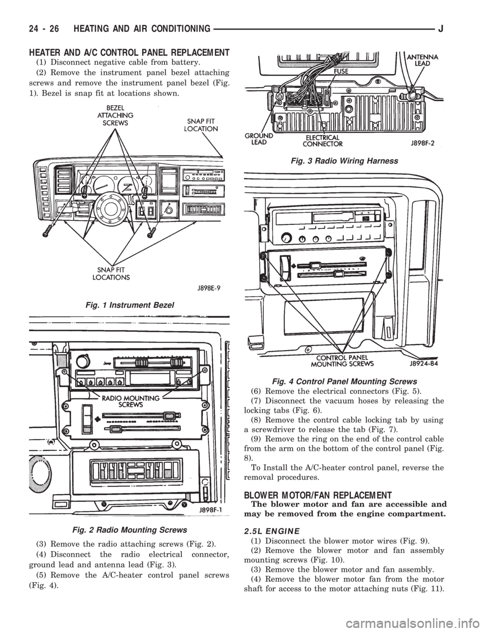
HEATER AND A/C CONTROL PANEL REPLACEMENT
(1) Disconnect negative cable from battery.
(2) Remove the instrument panel bezel attaching
screws and remove the instrument panel bezel (Fig.
1). Bezel is snap fit at locations shown.
(3) Remove the radio attaching screws (Fig. 2).
(4) Disconnect the radio electrical connector,
ground lead and antenna lead (Fig. 3).
(5) Remove the A/C-heater control panel screws
(Fig. 4).(6) Remove the electrical connectors (Fig. 5).
(7) Disconnect the vacuum hoses by releasing the
locking tabs (Fig. 6).
(8) Remove the control cable locking tab by using
a screwdriver to release the tab (Fig. 7).
(9) Remove the ring on the end of the control cable
from the arm on the bottom of the control panel (Fig.
8).
To Install the A/C-heater control panel, reverse the
removal procedures.
BLOWER MOTOR/FAN REPLACEMENT
The blower motor and fan are accessible and
may be removed from the engine compartment.
2.5L ENGINE
(1) Disconnect the blower motor wires (Fig. 9).
(2) Remove the blower motor and fan assembly
mounting screws (Fig. 10).
(3) Remove the blower motor and fan assembly.
(4) Remove the blower motor fan from the motor
shaft for access to the motor attaching nuts (Fig. 11).
Fig. 1 Instrument Bezel
Fig. 2 Radio Mounting Screws
Fig. 3 Radio Wiring Harness
Fig. 4 Control Panel Mounting Screws
24 - 26 HEATING AND AIR CONDITIONINGJ
Page 1730 of 1784
FOREWORD
The information contained in this service manual has been prepared for the professional automotive tech-
nician involved in daily repair operations. This manual does not cover theory of operation, which is addressed
in service training material. Information describing the operation and use of standard and optional equipment
is included in the Owner 's Manual provided with the vehicle.
Information in this manual is divided into groups. These groups contain general information, diagnosis,
testing, adjustments, removal, installation, disassembly, and assembly procedures for the components. To as-
sist in locating a group title page, use the Group Tab Locator on the following page. The solid bar after the
group title is aligned to a solid tab on the first page of each group. The first page of the group has a contents
section that lists major topics within the group. If you are not sure which Group contains the information you
need, look up the Component/System in the alphabetical index located in the rear of this manual.
A Service Manual Comment form is included at the rear of this manual. Use the form to provide Chrysler
Corporation with your comments and suggestions.
Tightening torques are provided as a specific value throughout this manual. This value represents the
midpoint of the acceptable engineering torque range for a given fastener application. These torque values are
intended for use in service assembly and installation procedures using the correct OEM fasteners. When re-
placing fasteners, always use the same type (part number) fastener as removed.
Chrysler Corporation reserves the right to change testing procedures, specifications, diagnosis, repair
methods, or vehicle wiring at any time without prior notice or incurring obligation.
NOTE: The acronyms, terminology and nomenclature used to identify emissions related components in
this manual may have changed from prior publications. These new terms are in compliance with S.A.E.
recommended practice J1930.
NEXT PAGE©
Page 1734 of 1784
FOREWORD
The information contained in this service manual
has been prepared for the professional automotive
technician involved in daily repair operations. This
manual does not cover theory of operation, which is
addressed in service training material. Information
describing the operation and use of standard and op-
tional equipment is included in the Owner 's Manual
provided with the vehicle.
This manual is designed as a supplement to be
used along with the 1994 Jeep Cherokee/Wrangler
Service Manual, 81-370-4146. It includes information
related to 1994 vehicles built after December, 1993.
It should be used in conjunction with the initial man-
ual for complete vehicle coverage.
This contains general information, diagnosis, and
testing procedures for the new R134a refrigerant sys-
tem.
The Component and System Index of th is man-
ual identifies the correct page for the component or
system to be serviced. In addition, a Service Manual
Comment form is included at the rear of this manual.
Use the form to provide Chrysler Corporation with
your comments and suggestions.
Chrysler Corporation reserves the right to
change testing procedures, specifications, diagnosis,
repair methods, or vehicle wiring at any time without
prior notice or incurring obligation.
HEATING AND AIR CONDITIONING 1
INDEX 1
Service Manual Comment Forms (Rear of Manual)
NOTE: The acronyms, terminology and nomenclature used to identify emissions related components in
this manual may have changed from prior publications. These new terms are in compliance with S.A.E.
recommended practice J1930.