1994 JEEP CHEROKEE warning light
[x] Cancel search: warning lightPage 8 of 1784
JUMP STARTING, HOISTING AND TOWING
JUMP STARTING
WARNING: DO NOT ATTEMPT TO PUSH OR TOW A
VEHICLE TO START THE ENGINE. UNBURNED
FUEL COULD ENTER THE EXHAUST CATALYTIC
CONVERTER AND IGNITE AFTER THE ENGINE IS
STARTED. THIS COULD CAUSE THE CONVERTER
TO OVERHEAT AND RUPTURE.
BOOSTER BATTERY
WARNING: TO PREVENT PERSONAL INJURY OR
CLOTHING DAMAGE, DO NOT ALLOW BATTERY
(ACID) TO CONTACT EYES, SKIN OR CLOTHING.
DO NOT LEAN OVER A BATTERY WHEN CON-
NECTING JUMPER CABLES. DO NOT ALLOW THE
POSITIVE AND NEGATIVE CABLE CONNECTOR
CLAMPS TO CONTACT EACH OTHER. KEEP OPEN
FLAMES AND SPARKS AWAY FROM THE BATTERY
VENT HOLES. ALWAYS WEAR EYE PROTECTION
WHEN INVOLVED WITH BATTERIES.
If it is necessary to use a booster battery and
jumper cables to start an engine use the following
procedure.
(1) Engage the parking brake and shift the auto-
matic transmission to PARK, manual transmission
shift to NEUTRAL.
(2) Turn off all lights, the heater-A/C blower mo-
tor, and all other electrical loads.
WARNING: WHEN THE AIR TEMPERATURE IS BE-
LOW THE FREEZING POINT (0ÉC OR 32ÉF), THE
ACID IN A DISCHARGED VEHICLE BATTERY CAN
FREEZE. DO NOT ATTEMPT TO JUMP START AN
ENGINE BEFORE DETERMINING THE CONDITION
OF THE BATTERY.
(3) Inspect the general condition of the battery.
CAUTION: Do not permit metal surfaces on vehicles
to contact because this could establish ground con-
tinuity between vehicle bodies.
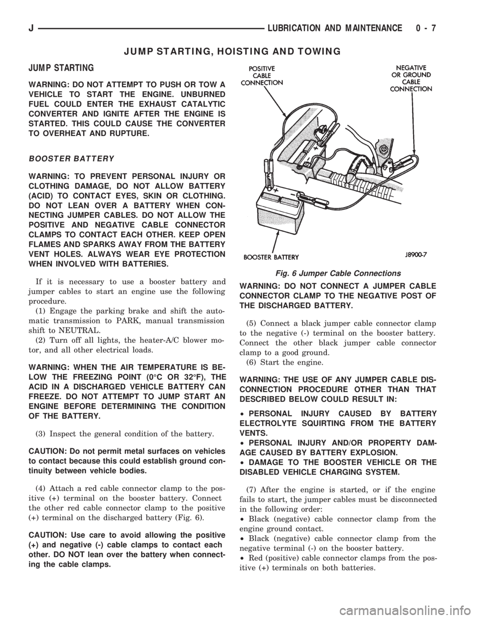
(4) Attach a red cable connector clamp to the pos-
itive (+) terminal on the booster battery. Connect
the other red cable connector clamp to the positive
(+) terminal on the discharged battery (Fig. 6).
CAUTION: Use care to avoid allowing the positive
(+) and negative (-) cable clamps to contact each
other. DO NOT lean over the battery when connect-
ing the cable clamps.WARNING: DO NOT CONNECT A JUMPER CABLE
CONNECTOR CLAMP TO THE NEGATIVE POST OF
THE DISCHARGED BATTERY.
(5) Connect a black jumper cable connector clamp
to the negative (-) terminal on the booster battery.
Connect the other black jumper cable connector
clamp to a good ground.
(6) Start the engine.
WARNING: THE USE OF ANY JUMPER CABLE DIS-
CONNECTION PROCEDURE OTHER THAN THAT
DESCRIBED BELOW COULD RESULT IN:
²PERSONAL INJURY CAUSED BY BATTERY
ELECTROLYTE SQUIRTING FROM THE BATTERY
VENTS.
²PERSONAL INJURY AND/OR PROPERTY DAM-
AGE CAUSED BY BATTERY EXPLOSION.
²DAMAGE TO THE BOOSTER VEHICLE OR THE
DISABLED VEHICLE CHARGING SYSTEM.
(7) After the engine is started, or if the engine
fails to start, the jumper cables must be disconnected
in the following order:
²Black (negative) cable connector clamp from the
engine ground contact.
²Black (negative) cable connector clamp from the
negative terminal (-) on the booster battery.
²Red (positive) cable connector clamps from the pos-
itive (+) terminals on both batteries.
Fig. 6 Jumper Cable Connections
JLUBRICATION AND MAINTENANCE 0 - 7
Page 16 of 1784
ENGINE OIL CHANGE AND FILTER REPLACEMENT
WARNING: CARE SHOULD BE TAKEN WHEN
CHANGING OIL. PROTECTIVE CLOTHING AND
GLOVES SHOULD BE WORN. EXPOSED SKIN
SHOULD BE WASHED WITH SOAP AND WATER TO
REMOVE ANY ENGINE OIL. DO NOT USE GASO-
LINE, THINNER, OR SOLVENTS TO REMOVE EN-
GINE OIL FROM SKIN.
REQUIRED MAINTENANCE
With normal driving conditions, engine oil and fil-
ter must be changed after each 12 000-km (7,500-
miles)/12-month interval. If the vehicle is involved
with a severe driving condition, after each 4 800-km
(3,000-miles)/3-month interval. A severe driving con-
dition includes:
²frequent short trip driving less than 24 km (15
miles);
²frequent driving in a dusty environment;
²trailer towing;
²extensive engine idling;
²sustained high-speed operation;
²desert operation;
²frequent starting and stopping;
²cold-climate operation;
²off-road driving; or
²commercial service.
OIL CHANGE AND FILTER REPLACEMENT
(1) Drain the engine oil from the crankcase. Wait
until after the engine has attained the normal oper-
ating temperature to ensure complete drainage of oil.
(2) Install the drain-hole plug with a replacement
gasket.
The oil filter should be replaced during every
engine oil change.
(3)
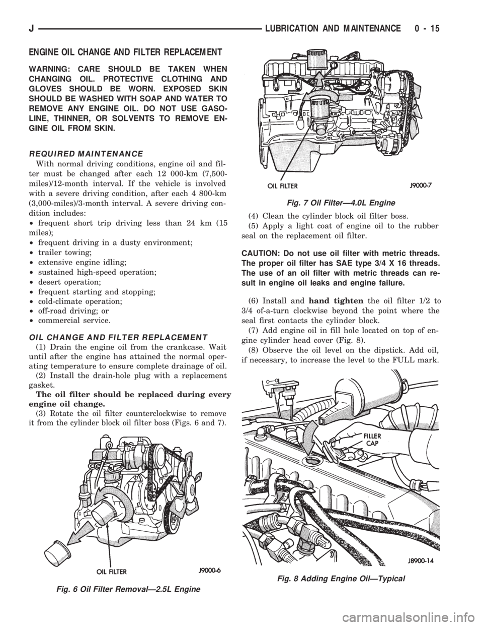
Rotate the oil filter counterclockwise to remove
it from the cylinder block oil filter boss (Figs. 6 and 7).
(4) Clean the cylinder block oil filter boss.
(5) Apply a light coat of engine oil to the rubber
seal on the replacement oil filter.
CAUTION: Do not use oil filter with metric threads.
The proper oil filter has SAE type 3/4 X 16 threads.
The use of an oil filter with metric threads can re-
sult in engine oil leaks and engine failure.
(6) Install andhand tightenthe oil filter 1/2 to
3/4 of-a-turn clockwise beyond the point where the
seal first contacts the cylinder block.
(7) Add engine oil in fill hole located on top of en-
gine cylinder head cover (Fig. 8).
(8) Observe the oil level on the dipstick. Add oil,
if necessary, to increase the level to the FULL mark.
Fig. 6 Oil Filter RemovalÐ2.5L Engine
Fig. 7 Oil FilterÐ4.0L Engine
Fig. 8 Adding Engine OilÐTypical
JLUBRICATION AND MAINTENANCE 0 - 15
Page 25 of 1784
dye to aid in detecting the source of ATF leaks. The
use of transmission sealing additives should also be
avoided.
Black-light detection dye is factory-installed in
automatic transmissions and, unless the ATF
has been drained and re-placed, it is not neces-
sary to add dye.
ATF LEVEL
Determine the ATF level according to the following
procedure.
WARNING: USE EXTREME CAUTION WHEN THE
ENGINE IS OPERATING. DO NOT PUT YOUR
HANDS NEAR THE DRIVE BELT, PULLEYS OR FAN
BLADE. DO NOT STAND IN A DIRECT LINE WITH
THE FAN BLADE.
(1) Operate the engine and allow the automatic
transmission sufficient time to warm to the normal
operating temperature (77ÉC/170ÉF).
When at normal operating temperature, ATF
will be uncomfortable to fingertips when the
dipstick is touched. Normally, 25 km (15 miles) is
a sufficient driving distance for a transmission
to warm to normal operating temperature (77ÉC/
170ÉF).
(2) Place the vehicle on a level surface.
(3) Operate the engine at idle speed.
(4) Engage the parking brake.
(5) Place a block in front of and at the rear of one
wheel/tire to prevent vehicle movement.
(6) Depress the brake pedal and move the trans-
mission selector lever through all the positions and
then place the selector lever in NEUTRAL position.
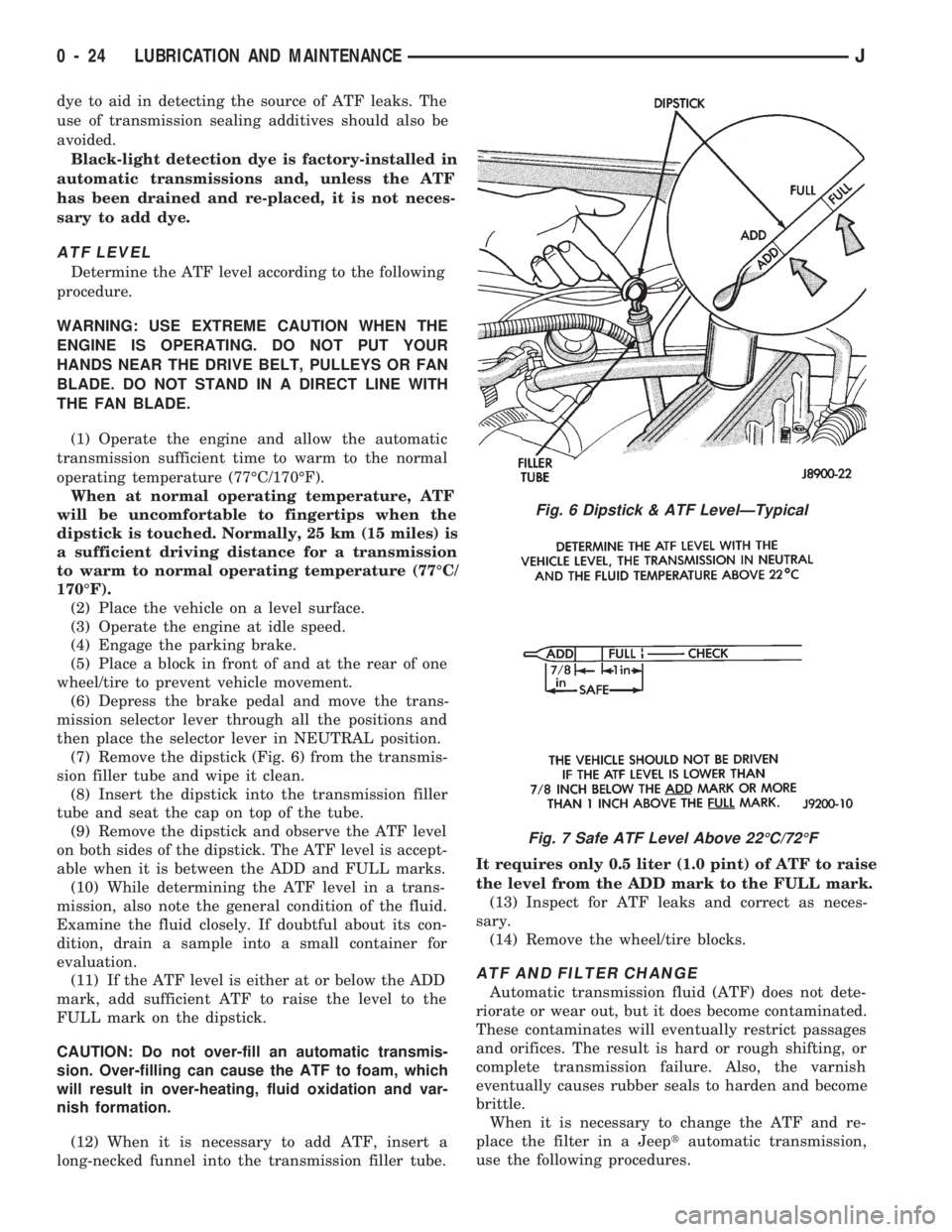
(7) Remove the dipstick (Fig. 6) from the transmis-
sion filler tube and wipe it clean.
(8) Insert the dipstick into the transmission filler
tube and seat the cap on top of the tube.
(9) Remove the dipstick and observe the ATF level
on both sides of the dipstick. The ATF level is accept-
able when it is between the ADD and FULL marks.
(10) While determining the ATF level in a trans-
mission, also note the general condition of the fluid.
Examine the fluid closely. If doubtful about its con-
dition, drain a sample into a small container for
evaluation.
(11) If the ATF level is either at or below the ADD
mark, add sufficient ATF to raise the level to the
FULL mark on the dipstick.
CAUTION: Do not over-fill an automatic transmis-
sion. Over-filling can cause the ATF to foam, which
will result in over-heating, fluid oxidation and var-
nish formation.
(12) When it is necessary to add ATF, insert a
long-necked funnel into the transmission filler tube.It requires only 0.5 liter (1.0 pint) of ATF to raise
the level from the ADD mark to the FULL mark.
(13) Inspect for ATF leaks and correct as neces-
sary.
(14) Remove the wheel/tire blocks.
ATF AND FILTER CHANGE
Automatic transmission fluid (ATF) does not dete-
riorate or wear out, but it does become contaminated.
These contaminates will eventually restrict passages
and orifices. The result is hard or rough shifting, or
complete transmission failure. Also, the varnish
eventually causes rubber seals to harden and become
brittle.
When it is necessary to change the ATF and re-
place the filter in a Jeeptautomatic transmission,
use the following procedures.
Fig. 6 Dipstick & ATF LevelÐTypical
Fig. 7 Safe ATF Level Above 22ÉC/72ÉF
0 - 24 LUBRICATION AND MAINTENANCEJ
Page 99 of 1784
REMOVALÐYJ MODELS
WARNING: EXTINGUISH ALL TOBACCO SMOKING
PRODUCTS BEFORE SERVICING THE FUEL SYS-
TEM. KEEP OPEN FLAME AWAY FROM FUEL SYS-
TEM COMPONENTS.
(1) Disconnect negative battery cable.
(2) Remove the fuel filler cap. Using an approved por-
table gasoline siphon/storage tank, drain fuel tank.
(3) Raise and support vehicle.
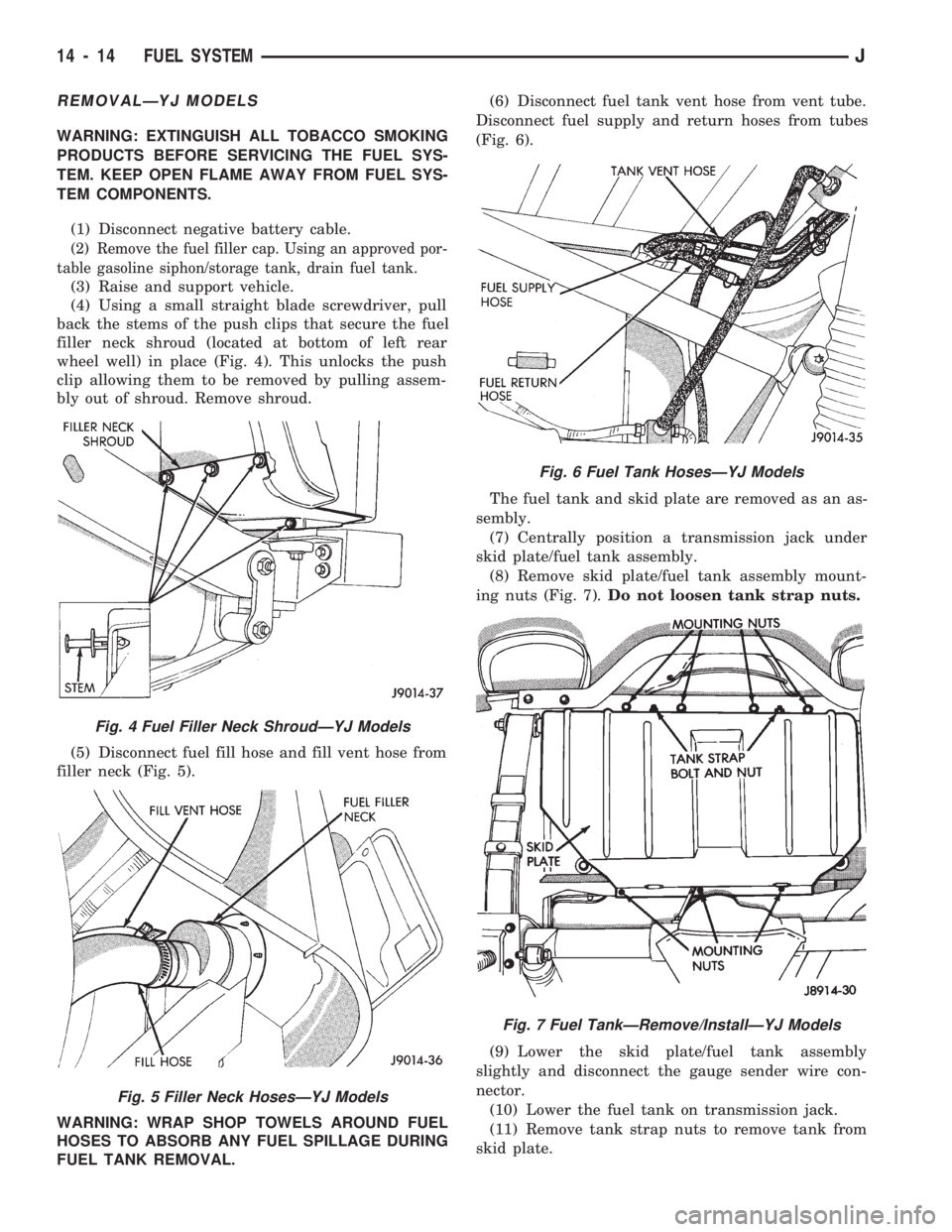
(4) Using a small straight blade screwdriver, pull
back the stems of the push clips that secure the fuel
filler neck shroud (located at bottom of left rear
wheel well) in place (Fig. 4). This unlocks the push
clip allowing them to be removed by pulling assem-
bly out of shroud. Remove shroud.
(5) Disconnect fuel fill hose and fill vent hose from
filler neck (Fig. 5).
WARNING: WRAP SHOP TOWELS AROUND FUEL
HOSES TO ABSORB ANY FUEL SPILLAGE DURING
FUEL TANK REMOVAL.(6) Disconnect fuel tank vent hose from vent tube.
Disconnect fuel supply and return hoses from tubes
(Fig. 6).
The fuel tank and skid plate are removed as an as-
sembly.
(7) Centrally position a transmission jack under
skid plate/fuel tank assembly.
(8) Remove skid plate/fuel tank assembly mount-
ing nuts (Fig. 7).Do not loosen tank strap nuts.
(9) Lower the skid plate/fuel tank assembly
slightly and disconnect the gauge sender wire con-
nector.
(10) Lower the fuel tank on transmission jack.
(11) Remove tank strap nuts to remove tank from
skid plate.
Fig. 4 Fuel Filler Neck ShroudÐYJ Models
Fig. 5 Filler Neck HosesÐYJ Models
Fig. 6 Fuel Tank HosesÐYJ Models
Fig. 7 Fuel TankÐRemove/InstallÐYJ Models
14 - 14 FUEL SYSTEMJ
Page 111 of 1784
ing the IAC motor pintle in and out of the air control
passage. The IAC motor is positioned when the igni-
tion key is turned to the On position.
A (factory adjusted) set screw is used to mechani-
cally limit the position of the throttle body throttle
plate.Never attempt to adjust the engine idle
speed using this screw.All idle speed functions are
controlled by the PCM.
IGNITION COILÐPCM OUTPUT
System voltage is supplied to the ignition coil pos-
itive terminal. The powertrain control module (PCM)
operates the ignition coil.Base (initial) ignition
timing is not adjustable.The PCM adjusts ignition
timing to meet changing engine operating conditions.
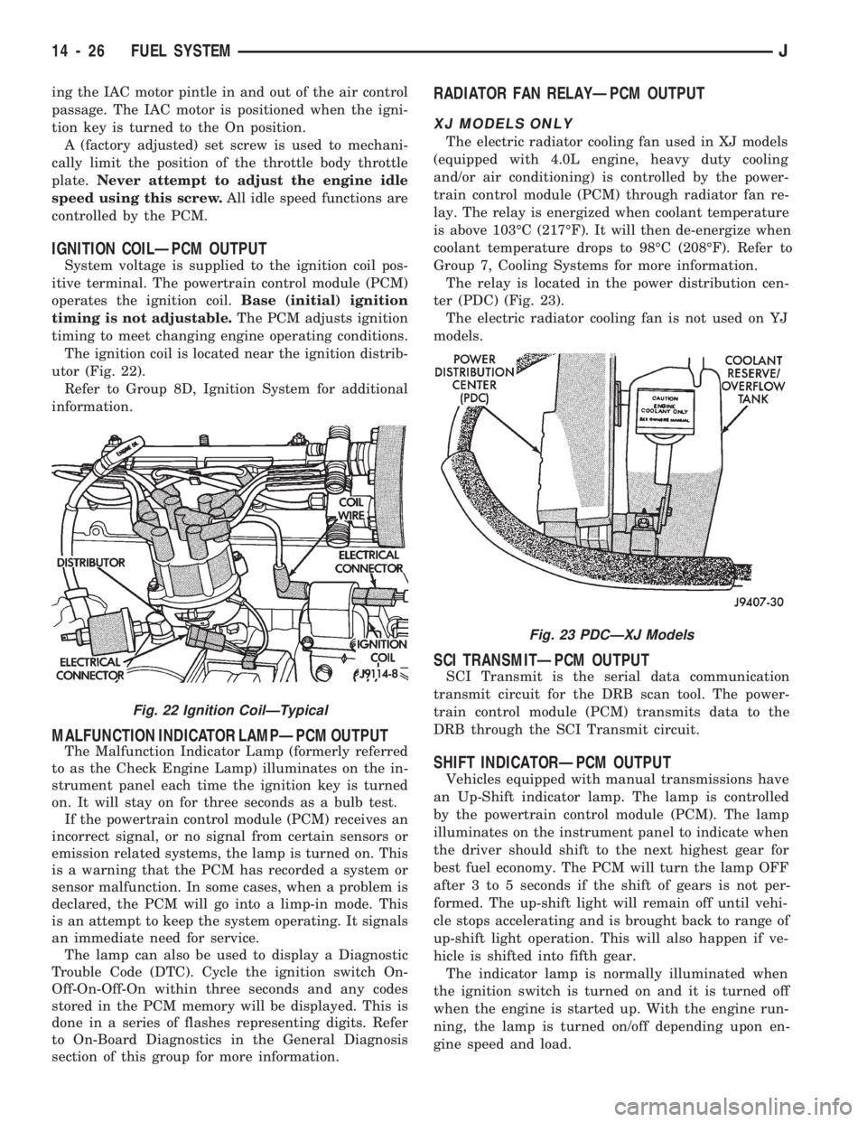
The ignition coil is located near the ignition distrib-
utor (Fig. 22).
Refer to Group 8D, Ignition System for additional
information.
MALFUNCTION INDICATOR LAMPÐPCM OUTPUT
The Malfunction Indicator Lamp (formerly referred
to as the Check Engine Lamp) illuminates on the in-
strument panel each time the ignition key is turned
on. It will stay on for three seconds as a bulb test.
If the powertrain control module (PCM) receives an
incorrect signal, or no signal from certain sensors or
emission related systems, the lamp is turned on. This
is a warning that the PCM has recorded a system or
sensor malfunction. In some cases, when a problem is
declared, the PCM will go into a limp-in mode. This
is an attempt to keep the system operating. It signals
an immediate need for service.
The lamp can also be used to display a Diagnostic
Trouble Code (DTC). Cycle the ignition switch On-
Off-On-Off-On within three seconds and any codes
stored in the PCM memory will be displayed. This is
done in a series of flashes representing digits. Refer
to On-Board Diagnostics in the General Diagnosis
section of this group for more information.
RADIATOR FAN RELAYÐPCM OUTPUT
XJ MODELS ONLY
The electric radiator cooling fan used in XJ models
(equipped with 4.0L engine, heavy duty cooling
and/or air conditioning) is controlled by the power-
train control module (PCM) through radiator fan re-
lay. The relay is energized when coolant temperature
is above 103ÉC (217ÉF). It will then de-energize when
coolant temperature drops to 98ÉC (208ÉF). Refer to
Group 7, Cooling Systems for more information.
The relay is located in the power distribution cen-
ter (PDC) (Fig. 23).
The electric radiator cooling fan is not used on YJ
models.
SCI TRANSMITÐPCM OUTPUT
SCI Transmit is the serial data communication
transmit circuit for the DRB scan tool. The power-
train control module (PCM) transmits data to the
DRB through the SCI Transmit circuit.
SHIFT INDICATORÐPCM OUTPUT
Vehicles equipped with manual transmissions have
an Up-Shift indicator lamp. The lamp is controlled
by the powertrain control module (PCM). The lamp
illuminates on the instrument panel to indicate when
the driver should shift to the next highest gear for
best fuel economy. The PCM will turn the lamp OFF
after 3 to 5 seconds if the shift of gears is not per-
formed. The up-shift light will remain off until vehi-
cle stops accelerating and is brought back to range of
up-shift light operation. This will also happen if ve-
hicle is shifted into fifth gear.
The indicator lamp is normally illuminated when
the ignition switch is turned on and it is turned off
when the engine is started up. With the engine run-
ning, the lamp is turned on/off depending upon en-
gine speed and load.
Fig. 23 PDCÐXJ Models
Fig. 22 Ignition CoilÐTypical
14 - 26 FUEL SYSTEMJ
Page 148 of 1784
BRAKES
CONTENTS
page page
ABS BRAKE DIAGNOSIS.................. 3
ABS COMPONENT SERVICE.............. 47
ABS SYSTEM OPERATION............... 39
ANTILOCK BRAKE SYSTEM OPERATION.... 43
BRAKE BLEEDINGÐBRAKE FLUID AND
LEVELÐBRAKELINES AND HOSES....... 13
BRAKE PEDAL AND BRAKELIGHT SWITCH . . 65
DISC BRAKES.......................... 24DRUM BRAKES........................ 34
GENERAL INFORMATION.................. 1
PARKING BRAKES...................... 56
POWER BRAKE BOOSTER................ 22
SERVICE BRAKE DIAGNOSIS.............. 7
SPECIFICATIONS....................... 67
STANDARD MASTER CYLINDER........... 20
GENERAL INFORMATION
INDEX
page page
Antilock Brake System (ABS)................ 1
Brake Fluid/Lubricants/Cleaning Solvents........ 1
Brake Safety Precautions................... 2
Brake Warning Lights...................... 1
Brakelining Material........................ 1Hydraulic Components..................... 1
Jeep Body Code Letters.................... 2
Power Brakes............................ 1
Wheel Brake Components................... 1
WHEEL BRAKE COMPONENTS
Front disc and rear drum brakes are used on all
models. The disc brake components consist of single
piston calipers and ventilated rotors. The rear drum
brakes are dual shoe, units with cast brake drums.
The parking brake mechanism is lever and cable
operated. The cables are attached to actuating levers
mounted on the rear drum brake secondary shoes.
The parking brake mechanism is operated by a foot
pedal on YJ models and a hand lever on XJ models.
POWER BRAKES
Power brakes are standard on all models. A vac-
uum operated power booster is used for standard and
ABS brake applications.
HYDRAULIC COMPONENTS
A dual reservoir master cylinder is used for all
standard brake applications. A combination propor-
tioning valve/pressure differential switch is used. A
center feed style master cylinder is used for ABS
brake applications.
BRAKELINING MATERIAL
The factory installed brakelining on all models con-
sists of an organic base material combined with me-
tallic particles. The lining does not contain asbestos.
BRAKE WARNING LIGHTS
A red, brake warning light is used to alert the
driver if a pressure differential exists between the
front and rear hydraulic systems. The light also
alerts the driver when the parking brakes are ap-
plied. The light illuminates for a few seconds at start
up as part of a bulb check procedure.
An additional warning light is used on models with
antilock brakes. This light is amber in color and is
located in the same side of the instrument cluster as
the red warning light. The amber light illuminates
only when an ABS system fault occurs.
ANTILOCK BRAKE SYSTEM (ABS)
An antilock brake system (ABS) is available on
XJ/YJ models. The system is an electronically oper-
ated, all-wheel brake control system. The ABS sys-
tem is designed to retard wheel lockup during
periods of high wheel slip braking. Refer to the anti-
lock brake section for operation and service informa-
tion.
BRAKE FLUID/LUBRICANTS/CLEANING SOLVENTS
Recommended fluid for all Jeep vehicles is Mopar
DOT 3 brake fluid, or an equivalent meeting SAE
J1703 and DOT 3 standards.
JBRAKES 5 - 1
Page 150 of 1784
ABS BRAKE DIAGNOSIS
INDEX
page page
ABS Fault Diagnosis....................... 4
ABS System Wiring and Electrical Circuits...... 4
ABS Warning Light Display.................. 3
Brake Warning Light Display................. 4
Diagnosis Procedures...................... 3
ECU Diagnosis........................... 4
HCU Diagnosis........................... 4Loss of Sensor Input....................... 3
Operating Sound Levels.................... 3
Rear Speed Sensor Air Gap................. 3
Steering Response........................ 3
Vehicle Response in Antilock Mode............ 3
Wheel/Tire Size and Input Signals............. 3
DIAGNOSIS PROCEDURES
ABS diagnosis involves three basic steps. First is
observation of the warning light display. Second is a
visual examination for low fluid level, leaks, parking
brakes applied, or obvious damage to system compo-
nents or wires. The third step involves using the
DRB II scan tool to identify a faulty component.
The visual examination requires a check of reser-
voir fluid level and all system components. Things to
look for are leaks, loose connections, or obvious com-
ponent damage.
The final diagnosis step involves using the DRB II
scan tool to determine the specific circuit or compo-
nent at fault. The tester is connected to the ABS di-
agnostic connector in the passenger compartment.
The connector is at the driver side of the center con-
sole under the instrument panel. Refer to the DRB II
scan tool Manual for tester procedures. Also refer to
the ABS Fault Diagnosis charts at the end of this
section for additional diagnosis information.
Initial faults should be cleared and the vehicle road
tested to reset any faults that remain in the system.
Faults can be cleared with the DRB II scan tool.
REAR SPEED SENSOR AIR GAP
The front wheel sensors are fixed and cannot be ad-
justed. Only the rear sensor air gap is adjustable. Air
gap must be set with a brass feeler gauge.
Correct air gap is important to proper signal gen-
eration. An air gap that is too large may cause com-
plete loss of sensor input. Or, a gap that is too small
could produce a false input signal, or damaging con-
tact between the sensor and tone ring.
WHEEL/TIRE SIZE AND INPUT SIGNALS
Antilock system operation is dependant on accurate
signals from the wheel speed sensors. Ideally, the ve-
hicle wheels and tires should all be the same size
and type. However, the Jeep ABS system is designed
to function with a compact spare tire installed.
OPERATING SOUND LEVELS
The ABS pump and solenoid valves may produce
some sound as they cycle on and off. This is a normal
condition and should not be mistaken for faulty oper-
ation.
VEHICLE RESPONSE IN ANTILOCK MODE
During antilock braking, the HCU solenoid valves
cycle rapidly in response to ECU inputs.
The driver will experience a pulsing sensation
within the vehicle as the solenoids decrease, hold, or
increase pressure as needed. A pulsing brake pedal
will also be noted.
The pulsing sensation occurs as the solenoids cycle
during antilock mode braking. A slight pulse in the
brake pedal may also be noted during the dynamic
self check part of system initialization.
STEERING RESPONSE
A modest amount of steering input is required dur-
ing extremely high deceleration braking, or when
braking on differing traction surfaces. An example of
differing traction surfaces would be when the left
side wheels are on ice and the right side wheels are
on dry pavement.
LOSS OF SENSOR INPUT
Sensor malfunctions will most likely be due to
loose connections, damaged sensor wires, incorrect
rear sensor air gap, or a malfunctioning sensor. Ad-
ditional causes of sensor faults would be sensor and
tone ring misalignment or damage.
ABS WARNING LIGHT DISPLAY
ABS Light Illuminates At Startup
The amber ABS light illuminates at startup as
part of the system self check feature. The light illu-
minates for 2-3 seconds then goes off as part of the
normal self check routine.
ABS Light Remains On After Startup
An ABS system fault is indicated when the light
remains on after startup. Diagnosis with the DRB II
JBRAKES 5 - 3
Page 151 of 1784

scan tool will be necessary to determine which ABS
component has malfunctioned.
ABS Light Illuminates During Brake Stop
A system fault such as loss of speed sensor signal
or solenoid failure, will cause the amber warning
light to illuminate. The most effective procedure here
is to check for obvious damage first. Then check the
electronic components with the DRB II scan tool.
BRAKE WARNING LIGHT DISPLAY
The red brake warning light and the ABS light op-
erate independently. If the red light remains on after
startup or illuminates during a brake stop, refer to
the standard brake system diagnosis section. Either
the parking brakes are applied, or a wheel brake
malfunction has occurred.
ECU DIAGNOSIS
The ECU controls all phases of antilock system op-
eration. It also differentiates between normal and an-
tilock mode braking.
The ECU monitors and processes the signals gen-
erated from all of the system sensors at all times.
The ECU program includes a self check routine
that tests each of the system components. The self
check occurs during both phases of the initialization
program. A failure of the self check program will
cause the immediate illumination of the amber warn-
ing light. The light will also illuminate if a solenoid
or other system component fails during the dynamic
phase of initialization.
If a system malfunction should occur, do not imme-
diately replace the ECU. A blown system fuse, bad
chassis ground, or loss of feed voltage will each cause
a system malfunction similar to an ECU failure.
Never replace the ECU unless diagnosis with the
DRB II scan tool indicates this is necessary.
HCU DIAGNOSIS
The HCU pump and motor and solenoid valve body
are serviced only as an assembly. The HCU assembly
should not be replaced unless a fault has actually
been confirmed. Verify fault conditions with the DRB
II scan tool before proceeding with repair.
ABS SYSTEM WIRING AND ELECTRICAL CIRCUITS
Location of the ABS fuse (in the fuse panel) is
shown in Figure 1. The engine compartment harness
routing for the ABS components is shown in Figure 2.
ABS FAULT DIAGNOSIS
The fault diagnosis chart provides additional infor-
mation on potential ABS system faults. Use the
chart as a guide when diagnosing a system problem.
Fig. 1 ABS Fuse Location
5 - 4 BRAKESJ