Page 1247 of 1413

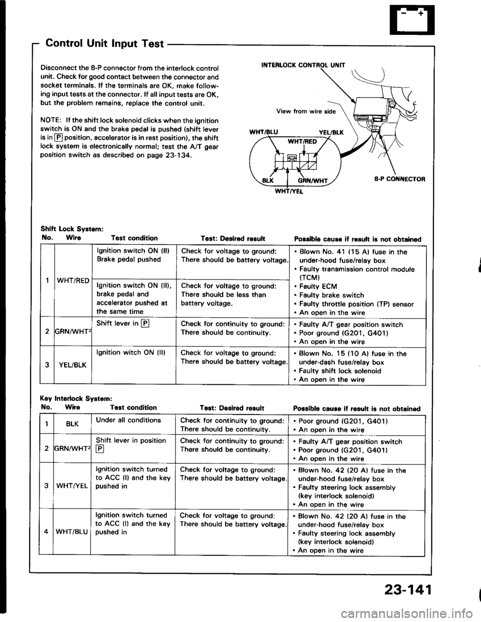
Control Unit Input Test
Oisconnect the 8-P connector from the interlock control
unit. Check for good contact between the connector and
socket terminals. lf the terminals 8re OK, make Iollow-
ing input tests at the connector. lf all input tests are OK,
but the problem remains, replace the cont.ol unit,
NOTE: lf the shilt lock solenoid clicks when the ignition
switch is ON and the brake pedal is pushed (shift tever
is in lfl position, accelerator is in rest position), the shiftlock system is electronically normal; test the A/T gear
positaon switch as described on page 23- 134.
Shift Lock Sy.tem:
No, Wlr6 Tost condition
Koy Intodock Systam:
No. WireT6st condition
Tost: Dosired resultPossiblo cause if rssuh is not obtainod
T6st: Desiled reaultPossible caure if rosult is not obtainsd
'I
lgnition switch ON (ll)
Brake pedal pushedCheck for voltage to ground:
There should be bsttery voltage
Blown No. 41 (15 A) fuse in the
under-hood fuse/relay box
Faulty transmission control module(TCM}
Faulty ECM
Faultv brake switch
Faulty throftle position lTP) sensor
An oDen in the wire
wn t/hEulgnition switch ON
brske pedal and
accelerator pushed
the same time
I [),
at
Check for voltage to ground:
There should be less than
battery voltage.
GRN^/vHT'
Shift lever in @Check lol continuity to ground:
There should be continuity.
Faulty A/T gear position switch
Poor ground {G201, G401}
An oDen in the wire
YEL/BLK
lgnition witch ON (lllCheck for voltage to ground:
There should be battery voltage
Blown No. 15 (10 A) luse in the
under-dash fuse/relay box
Faulty shift lock solenoid
An oDen in the wire
BLKUnder all conditionsCheck for continuity to ground:
There should be continuitv.
. Poor ground (G2O1, G4O1). An ooen in the wire
2
Shift lever in position
E
Check for continuity to ground;
Ther€ should be continuity.
Faulty A/T gear position swirch
Poor ground (c2O1 , G4O1)
An oDen in the wire
3WHTAYEL
lgnition switch tu.ned
to ACC (ll 8nd the keypushed in
Check for voltage to ground:
There should be battery voltage
Bfown No. 42 l2O Al fuse in the
under-hood tuse/relay box
Faulty steering lock assembly(kev interlock solonoid)
An oDen in the wire
4WHT/BLU
lgnition switch turned
to ACC (ll and the keypushed in
Check tor voltage to ground:
There should be batery voltage,
Bfown No. 42 l2O Al fuse in the
under-hood fuse/relav box
Faulty steering lock assembly(key interlock solenoid)
An oDen in the wire
23-141
Page 1255 of 1413

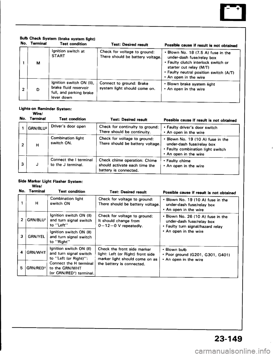
Bulb Check System
No. Tsrminal
(blake system lightl
Test condition
Lights-on Romind6r Systom:
Wire/
No, ToiminalT6Et condition
Side Markol Light Flashar System:
Wiro/
No. TerminalTest condition
Tost: Desirod resuhPossibls caus6 it result is not obtainod
Tost: Dositod rosuhPossibl6 caus6 if rosuh is not obtainod
Tast: Desired rosultPo$ible cause if result is not obtained
IM
lgnition switch at
STARTCheck lor voltage to ground:
There should be battery voltage.
Blown No. 18 {7.5 Al fuse in theunder-dash fuse/relay box
Faulty clutch int€rlock switch or
starter cut relay {M/T}Faulty neutral position switch (A/T)
An open in the wire
D
lgnition switch ON (ll),
brake fluid reservoir
tull, and parking brake
lever down
Connect to ground: Brake
system light should come on.
. Blown brake system light. An oDen in the wire
GRN/8LU'Driver's door openCheck for continuity to ground:
There should be continuity.
. Faulty driver's door switch. An oDen in the wire
H
Combination light
switch ON.
Check for voltage to g.ound:
There should be battery voltage
Blown No. l9 (1O A) tuse in the
under-dash fuse/relav box
Faulty combination light switch
An oDen in the wire
5
Connect the I terminal
to the J terminal.
Check chime operation: Chime
should activate each time the
batterv is connected,
. Faulty chime. An open in the wire
1H
Combination light
switch ON
Check for voltage to ground:
There should be battery voltage
. Blown No. 19 (1O A) tuse in the
under-dash fuse/relay box. An open in the wire
GRN/BLU1
lgnition switch ON {ll)and turn signal switch
to "Left"
Check for voltage to ground:
It should change from
O-12-O V repeatedly.
Blown No. 26 (10 A) luse in theunder-dash fuse/relav box
Faulty turn signal/hazard relay
An oDen in the wire2GRN/YEL
lgnition switch ON {ll)and turn signal switch
to "Right"
4GRN/WHTlgnition switch ON (ll)
and turn signal switch
to "Left (or Rightl":
Connect the H terminal
to the GRNMHT(or GRN/REDl) terminal.
Check the front side marker
light: Left (or Right) front sidemarker light should come on asthe batterv is connected.
Blown bulb
Poor ground (G2O1, c3O1, G4O1lAn open in the wire
GRN/REDl
23-149
Page 1261 of 1413
Gircuit Diagram (Canadal
BATTERY
G"*
UNOER_HOOD FUSEiRETAY 8OX
coMBrNAtor{ rcHrswnc
-il w
| '.=r" I
ll'L I I
I I *o\." l-'li' ;- ;j
I LI
"- r.r-,9 "orr
I
d "
L
RED/BLU REO/}VHT RED,ll
I UNDEN-DASH II FUSEiIEI,AY 8OX I
tl
L-J
t'GRN
/d\BATtG2\9-l
rGNrTrot{swITcH
No.2lfl0A)\I
No.l9|l04]Jm.tr (
t10A) ttt
I
No.l6{7.54}
tl
i,"#
llrrff li'rrt,
RED/GRtIIBLU REOr'TVHTINED/B
V
WHTTYEL
. DASH LGHTS BRIGHTNESSCOI{TROLLER. DASH I-IGHTS. PARKING I-GHIS. TAII,LIGHTS. UCENSE N"AT€ LIGI{TS
I a-rneonru jllA/Vr l"o I f# wxrintoRED/GRI{ +\{H I
DAYTIME RUNNINGUGI{TS RESISTOR
IRED/GRN
Hr I r-01651,1/) | l55W)HIt85W)LOt55Wl
HIGH BEAMINOICATORUGHTfl.4W
I
RIGHTHEADLIGHTPARKIIIGBRAKEsw{TcH
23-155
Page 1263 of 1413

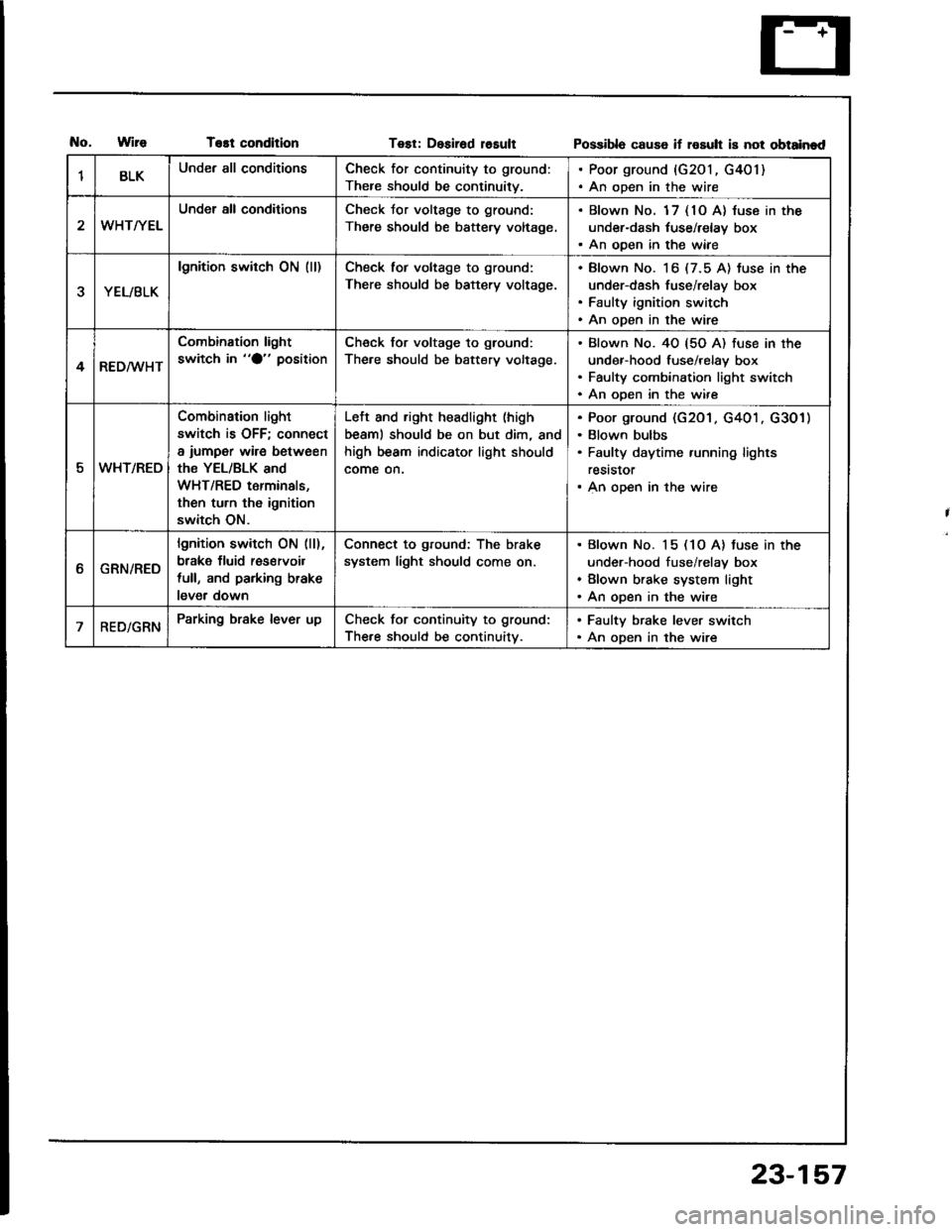
T€st conditionTest: Desirad losultPossibla cause if rosult is not obtainad
1BLKUnder all conditionsCheck for continuity to ground:
There should be continuity.
. Poor ground {G201, G401). An open in the wire
WHT/YEL
Under all conditionsCheck Jor voltage to ground:
There should be battery voltage.
. Blown No. 1 7 { 10 A} luse in the
under-dash tuse/relay box. An ooen in the wiae
YEL/BLK
lgnition switch ON (ll)Check tor voltage to ground:
There should be battery voltage.
Blown No. 16 (7.5 A) tuse in the
under-dash fuse/relay box
Faulty ignition switch
An open in the wire
4RED/WHT
Combination light
switch in "O" positionCheck for voltage to ground:
The.e should be battery voltage.
Blown No. 40 {5O A) fuse in the
under-hood fuse/relay box
Faulty combination light switch
An ooen in the wire
5WHT/REO
Combination light
switch is OFF; connect
a iumper wire between
the YEL/BLK and
WHT/RED terminals,
then turn th6 ignition
switch ON.
Left and right headlight (high
beaml should be on but dim, and
high beam indicator light should
come on.
Poor ground (G201 . G401 . G301)
Blown bulbs
Faulty daytime running lights
reststor
An open in the wire
ttGRN/RED
lgnition switch ON (ll),
brake fluid res€rvoil
full, and parking brake
lever down
Connect to ground: The brake
system light should come on.
Blown No. 15 (1O A) tuse in the
under-hood fuse/relay box
Blown brake system light
An open in the wire
RED/GRNParking brake lever upCheck for continuity to ground:
The.e should be continuitv.
. Faulty brake lever switch. An open in the wire
23-157
Page 1272 of 1413
-
Taillights (Hatchbackl
Replacement
23-166
1.Open the resr hatch.
Remove the rear panellining and the side lining {see
section 20).
Disconnect the 4-P connector from the taillight.
Remove the six mounting nuts, then pull out the
taillight.
4.
NOTE:
a Inspect the gasket. Replace it if it is distorted or
stavs compresseo.
a After installation. run wate. over ths lights to
make sure thev don't leak.
4-P CON[{ECTOR
BulbReplacement
R6ei tum slgnal/Rolr parking lights:
1 . Open the rear hatch, then remove the access panel.
2. Remove the bulb lrom the bulb socket.
@: REAR TURN SIGNAL LIGHT BULB (32 CPI
@: REAR PARKING LIGHT BULB {3 CP)
Brake/T8illight/Back-up lights:
1. ODen the rear hatch.
2. Remove the rear panel lining {see section 20).
BACK-UP LIGHT BULB {32 CP}
ERAKE/TAILLIGHT BULB (32l3 CP)
o:
@:
ACCESS PANEL
Page 1274 of 1413
Taillights (Sedanl
Bulb Replacement
Tsillight:
1. Open the trunk lid. then remove the rear panel lin-
ing and side lining {see section 20}.
2. Remove the bulb from the bulb socket.
lnnor T.illlght:
1. Open the trunk lid, then remove the bulb housing.
2. Remove the bulb from the bulb housing.
@:
@:
@:
BRAKE/TAILLIGHT BULB (32l3 CP}
TURN SIGNAL LIGHT BULB (32 CP}
REAR PARKING LIGHT BULB {3 CP)
O:
@:
BACK-UP LIGHT BULB (32 CP}
BRAKE/TAILLIGHT BULB I3213 CP}
BULB HOUSII{G
23-168
l'r'qn'F',
Page 1287 of 1413
Circuit Diagram
Brake Lights
UNDEE-HOOOFUSE/NELAY BOX
. HORi{. IMTERI.OCK SYSTEM
{.BLK
*H-i
{.{u8tK
23-181
Page 1288 of 1413
AB'|Frt
jr'li
CD
Brake Lights
Brake Switch Test
lf the brake lights do not go on, check the No. 42
{2O A) fuse in the under-hood fuse/relay box, and
the brake light bulbs in the taillighr assembly and high
mount brake light.
lf the fuse and bulbs are OK. disconnect the 2-P or
4-P connector {rom the brake switch.
3. Check fo. continuitv between the B and C terminals.
There should be continuity with the brake pedal
pushed.
a lJ there is no continuitv, replsce the switch or ad-
just pedal height {see section 19).
a lf there is continuity, but the brake lights do not
go on, inspect for:- Poor ground (G5O3)
- An ooen in the wire
High Mount Brake Light Replacement
(LED typel
1. Remove the four screws and the high mount btake
light, then disconnect the connectors.
HIGH ltlOUt{T BRAKE LIGHT {LED TYPEI
23-1A2