Page 1134 of 1413
Connector ldentification and Wire Harness Routing
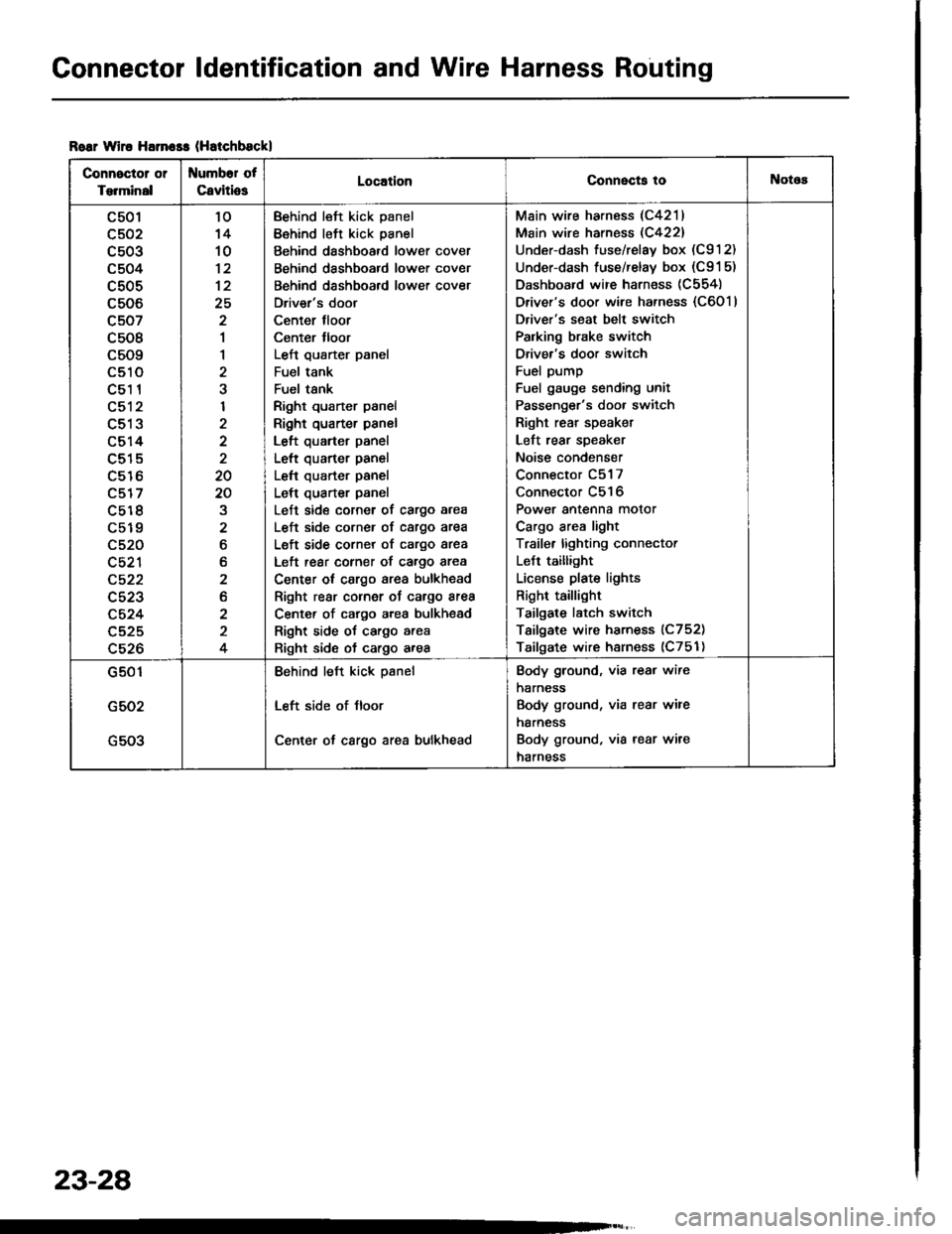
Roar wiro Harn$s (Hatchbsckl
Connector or
Torminal
Numbor of
CavitiosLocationConnecta tollotos
c501
c502
c503
c504
c505
c506
c507
c508
c509
LStt
c51 1
c512
c513
c514
c515
c516
c517
c5r 8
c519
c520
c521
c522
c523
c524
c525
c526
10'14
10
12
25
2
1
1
2
I
2
20
20
2
6
b
2
2
2
4
Behind left kick panel
Behind left kick panel
Behind dashboard lower cover
Behind dashboard lower cover
Behind dashboard lower cover
Driver's door
Center tloor
Center lloor
Left qusrter panel
Fuel tank
Fuel tsnk
Right quarter panel
Right quarter panel
Left quarter panel
Left quarter panel
Left quarter panel
Left quarter panel
Left side corner of cargo area
L€ft side corner of cargo area
Left side corner of cargo area
Left rear corner of cargo area
Center ot cargo area bulkhead
Right rear cornor oJ cargo area
Center of cargo area bulkhsad
Right side of cargo area
Right side of cargo area
Main wire harness (C4211
Main wire harness (C422)
Under-dash fuse/relay box (C912)
Under-dash fuse/relay box (C91 5)
Dashboard wire harness (C554)
Driver's door wire harness {C6011
Driver's seat belt switch
Palking brake switch
Driver's door switch
Fuel pump
Fuel gauge sending unit
Passenger's door switch
Right rear speaket
Left rear speaker
Noise condenser
Connector C517
Connector C516
Power antenna motor
Cargo area light
Traile. lighting connector
LeJt taillight
License plate lights
Right taillight
Tailgate latch switch
Tailgate wire harness (C752)
Tailgate wire harness (C751)
G501
G502
G503
Behind left kick psnel
Left side of Jloor
Center ot cargo area bulkhead
Body ground, via rear wire
harness
Body ground, via rear wire
harness
Body ground, via rear wire
harness
23-28
Page 1136 of 1413
Connector ldentification and Wire Harness Routing
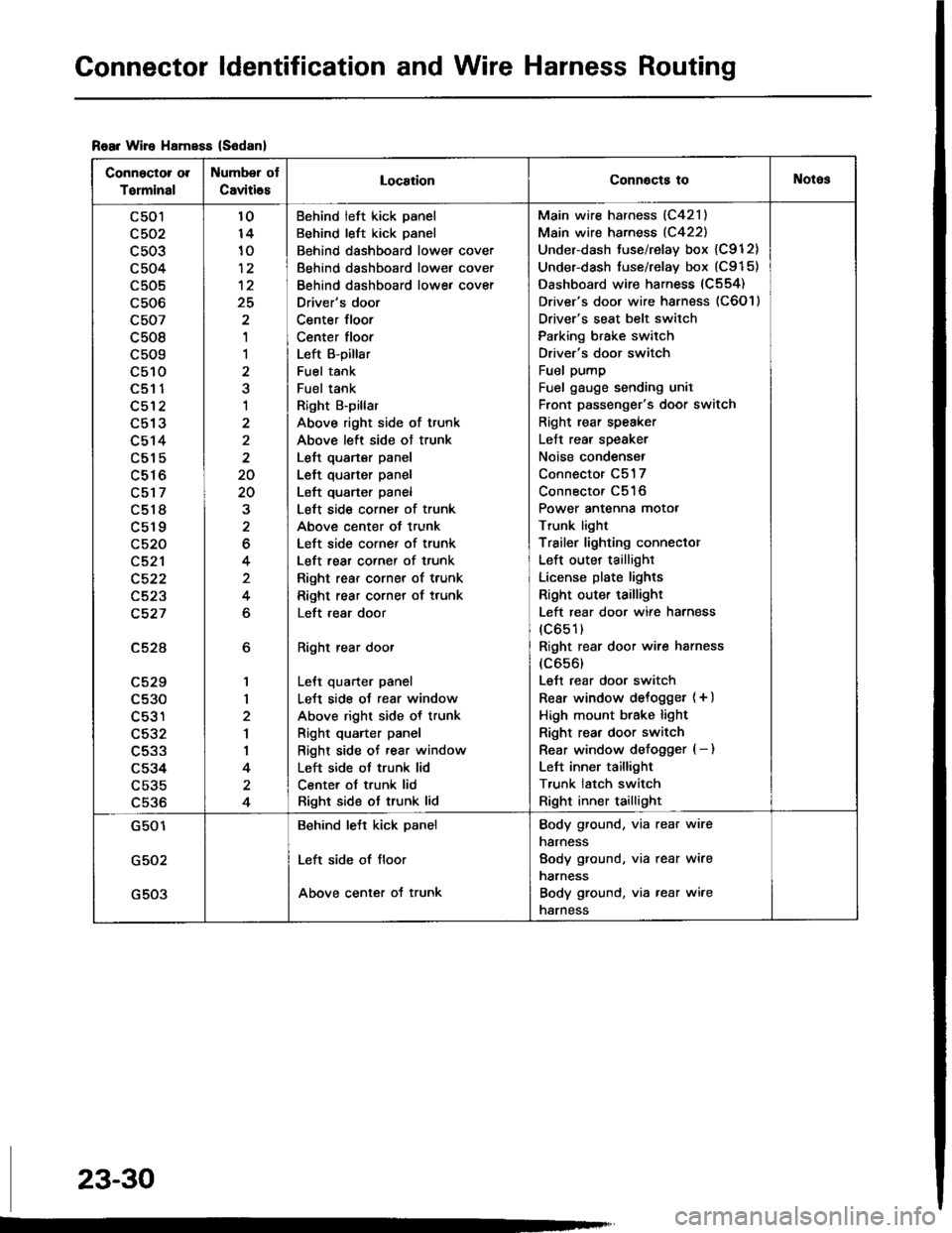
Rear Wire HamsEs (S6danl
Connector ol
Torminal
Number ot
Caviti6sLocaiionConnocts toNotos
c501
c503
c504
c505
c506
c507
c508
c509
c510aEt t
c512
L9 IJ
c514
c515
c516
c517
c518
c519
c520
c521
c522
c523
c527
c52A
LCZY
c530
c531
c532
c533
c534
c535
c536
6
1,|
2
1
I
4
4
10
10
12
25
'I
1
a
1
2
2
20
20
2
6
4
4
6
Behind left kick panel
Behind left kick panel
Behind dashboard lower cover
Behind dashboard lower cover
Behind dashboard lowe, cover
Driver's door
Center floor
Center floor
Left B-pillar
Fuel tank
Fuel tank
Right B'pillar
Above right side of trunk
Above left side ot trunk
Left quarter panel
Left quarter panel
Left quarter panel
Left side corner of trunk
Above center of trunk
Left side corner of trunk
Left rear corner of trunk
Right rear corner of trunk
Right rear corner of trunk
Left ,ear door
Right rear door
LeJt quarter panel
LeJt side oJ rear window
Above right side of trunk
Right quarter panel
Right side of rear window
Left side ot trunk lid
Center ot trunk lid
Right side ot trunk lid
Main wire harness (C421)
Main wire harness (C422)
Under-dash tuse/relay box {C912}
Under-dash fuse/relay box (C915)
Dashboard wire harness (C554)
Driver's door wire harness (C6O l )
Driver's seat belt switch
Parking brake switch
Driver's door switch
Fuel pump
Fuel gauge sending unil
Front passenger's door switch
Right rear speaker
Left rear speaker
Noise condenser
Connector C517
Connector C516
Power antenna motor
Trunk light
Trailer lighting conneclor
Left outer taillighr
License plate lights
Right outer taillighr
Left rear door wire harness
(c651)
Right rear door wire harness
(c656)
Lett rear door switch
Rear window delogget (+ )
High mount btake light
Right rear door switch
Rear window defogger (- )
Left inner taillight
T,unk latch switch
Right inner taillight
G501
G502
G503
Behind lett kick panel
Left side of floor
Above center of trunk
Body ground, via rear wire
narness
Body ground, via rear wire
narness
Body ground, via rear wire
narness
23-30
Page 1150 of 1413
Connector ldentification and Wire Harness Routing
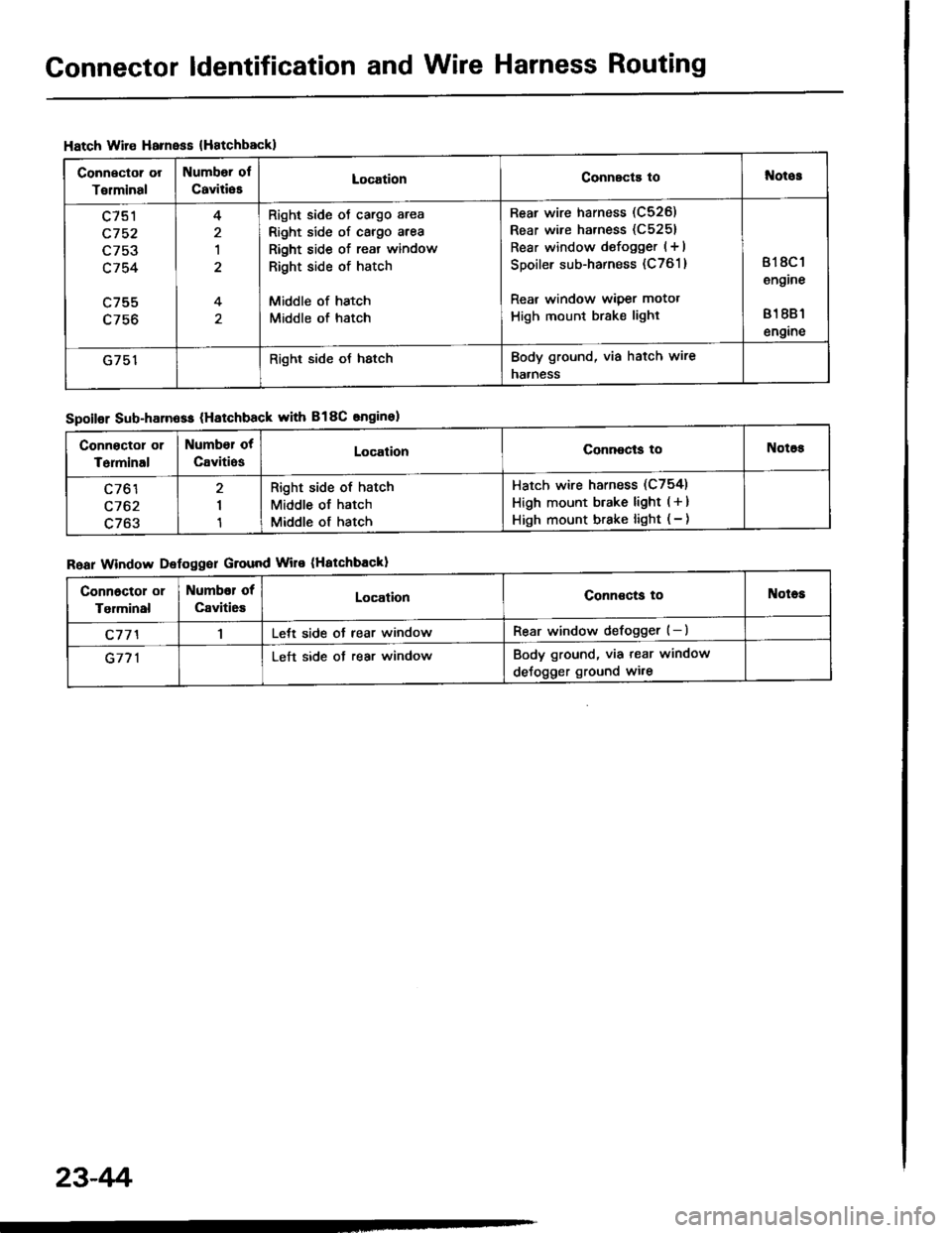
Hatch Wire Harnsss {Hatchbackl
Connector or
Torminal
Numbor ol
CaviliesLocationConnscts tol{otos
c751
c752
L/5J
c754
c755
4
1
4
Right side oJ cargo area
Right side of cargo area
Right side of reat window
Right side of hatch
Middle of hatch
Middle of hatch
Rear wire harness (C526)
Rear wire harness (C5251
Rear window defogger (+ I
Spoiler sub-harness (C761 )
Rear window wiper motot
High mount brake light
818C 1
engine
81 881
engine
G751Right side oJ hstchBody ground, via hatch wire
naaness
Spoilor Sub-harn6ss (Hatchback with B18C snginel
Roar Window Defoggor Ground Wire (Hatchbackl
Connoctor or
Terminal
Number ot
CavitiosLocalionConnocls toNotos
c761
c762
c763
I
1
Right side of hatch
Middle of hatch
Middle of hatch
Hatch wire harness (C754)
High mount btake light ( + )
High mount brake light ( - )
Connoctol or
Tgrminal
Numbor of
Caviti6sLocationConnoctg toNotes
c77'l1Lett side ot rear windowRear window defogger (-)
G771Left side ot rear windowBody ground, via tear window
deJogger ground wi.e
23-4r'i
Page 1158 of 1413
Fuses
Under-hood Fuse/Relay Box
ALTERI{ATOR
fTo .ngino wlto hsrno$ {Tlolll
Not usod
r: l\lot u3.d
umborAmpsColor
nF n nn46 45 /t4 35 3l
UU U UU
n32
U
n
33
U
r:rg
U
n
42
U
n43
U
[To rldidor hn r.l.Yl
Componon! (sl 01 Clrcuit 13) Protoqtod
3115 AYEL/WHTPGM-Fl main relay
327.5 AWHT/BLUECM, TCM. Clock, Stereo radio/cassette plsyer, Maintenance reminder unit
a2204BLK/REDRadiator Jan motor
34Not used
35204WHTCondenser fan motor, A/C compressor clutch
50AWHT/REDNo. I {3O A), No. 3 (7.5 A). No. 4l2O Al, No 5 (2O A), No. 7 (2O A),
No. I (20 A) fuses
3740ABLU/lVHTBlower motor
3830ABLK/GRNRear window defogger, Noise condenser
?q50AWHT/BLKlgnition switch {BAT}
4050AWHTCombination light switch, No. 17 (1O Al fuse
41100 APower distribution
4220AWHT/GRNHorn system, Brake system, Key interlock solenoid (Aff)
4310 AWHT/GRNTurn signal/hazard.elay
44Not used
45Not used
46Not used
23-52
Page 1219 of 1413
Gauge Assembly
Component Location Index
CAUTION:
a All SRS electrical wiring harnosses are cov€rod withyellow insulation.
a Bofore disconnecting any prn ot th€ SRS wire har-ness, connect tho short connector(sl.a R€place th6 entirs affGcted SRS halne$ assembly ifit has an open circuit o? damaged wiring.
SRS MAIN HARNESS{Cov.r6d with yollow inrularionl
GAUGE ASSEMBLYGauge Location Index, page 23-114Indicator Location Index, page 23-1 14Terminal Location Index, page 23-114Bulb Location. page 23-'l 15Disassembly. page 23-1 19Removal, page 23-118
FUEL GAUGE SENDING UNtTTest, page 23'124Repfacemenr, page 23-124
VEHICLE SPEEO SENSOB IVSS}Test, page 23-120fnput Test. page 23-120Repfacement, page 23-122
PARKITTG BRAKE SWITCHTest, page 23-127
BRAKE FLUID LEVEL SWITCHTesr, page 23-127
EI{GINE OIL PBESSURE SWITCHTest, page 23-122
ENGINE COOLANT TEMPERATURE IECTI GAUGESENOING UNITTest, page 23-126
(C61'ios tho SBS indicator signal)
23-113
Page 1233 of 1413
Brake System lndicator
Parking Brake Switch Test
Remove the tloor console, and disconnect the con-
nector from the switch.
Check for continuity b€tween the positive terminal
and body ground in each lever position accordino to
the table.
Canada:
lf the parking brake switch is OK, but ths brake sys-
tem indicator does not function, pertorm the input
test for the daytime running lights control unit (see
page 23-156).
L6vor position
TorminalPOSITIVEEODY
UP
DOWN
Brake Fluid Level Switch Test
Remove the reservoir caD.
Check that the tloat moves up and down freely, if
it does not, replace the reservoir cap sssembly.
Chsck for continuitv between the terminals in each
float position according to the table.
RESERVOIR CAPDOWN POSITION
when float drops.
4. lf necessary, replace the reservoir cap assemblv.
Terminal
Float positionPOSITIVENEGATIVE
UP
DOWN-o
POStTtVE
TERMINAL
Switch contacts open atproper fluid level.
23-127
Page 1241 of 1413
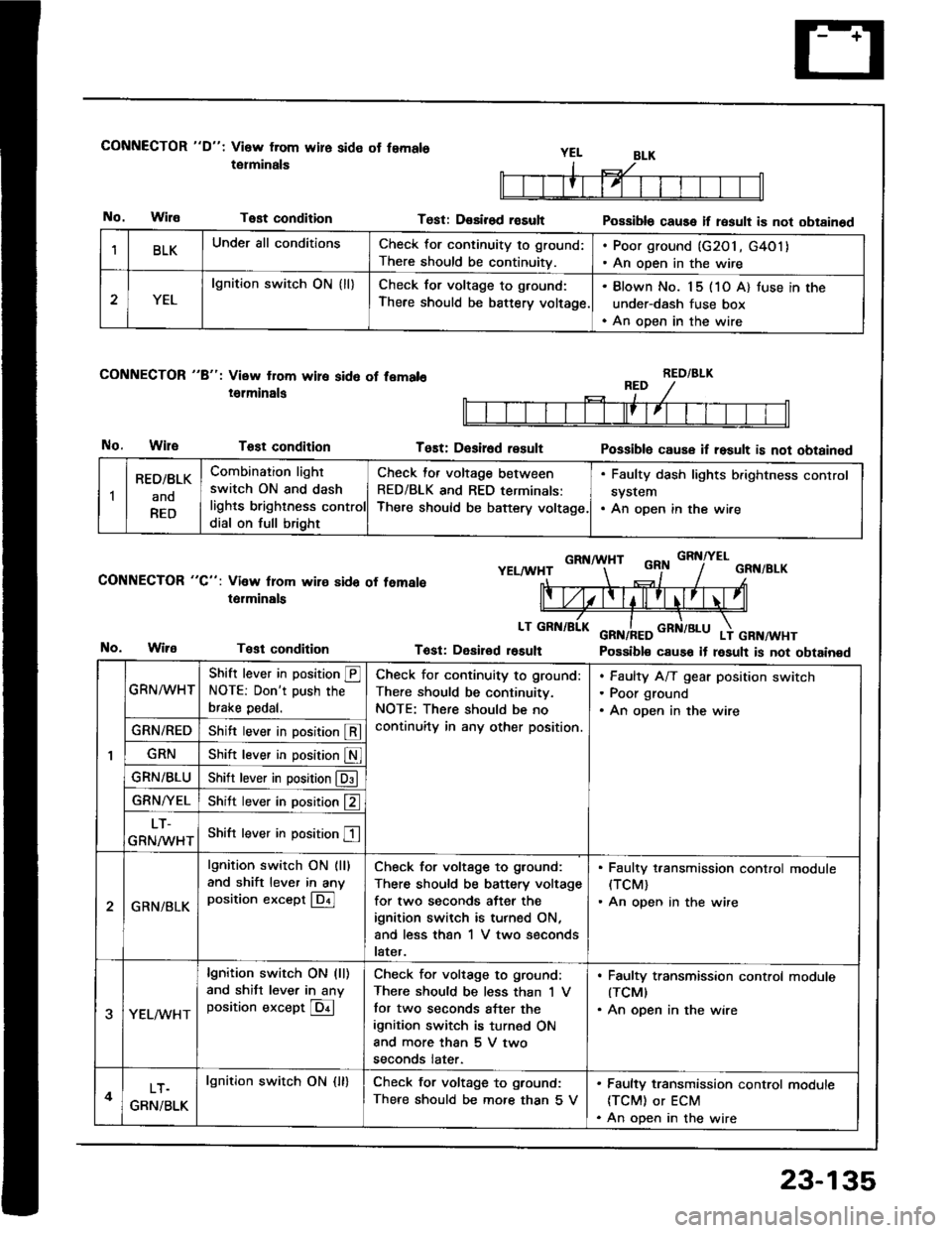
CONNECTOR "D": Visw from wire side ot femals
tetminals
No.WilaTest condition
CONNECTOR "8": View from wire sid6 of fem.l6
i6lminals
No.WileTost condition
CONNECTOR "C": Vi3w lrom wire sido of temale
t6rminals
Test condition
Test: D€sirod rasultPossible cause if result is not obtainod
Tost: D€sir6d resultPossiblo cause if result is not obtained
GRNA HTGRNITELYELAA'HTGRN/BLK
Tost: Desirod r6sult Possible cause it result is not obtainedNo.
BLKUnder all conditionsCheck for continuity to ground:
There should be continuitv.
. Poor ground (G2O1, G4O1). An open in the wire
2YEL
lgnition switch ON { ll}Check for voltage to ground:
There should be battery voltage.
. Blown No. 15 (1O A) tuse in the
under-dash fuse box. An open in the wire
RED/BLK
1
RED/BLK
ano
RED
Combination light
switch ON and dash
lights brighlness control
dial on full bright
Check for voltage between
RED/BLK and RED terminals:
There should be baftery voltage.
. Faulty dash lights b.ightness control
system. An open in the wire
GRN^^/HT
Shift lever in position @NOTE: Don't push the
brake pedal.
Check for continuity to ground:
There should be continuitv.
NOTE: There should be no
continuity in any other position.
Faulty A/T gear position switch
Poor ground
An open in the wire
GRN/REDShift lever in position @
GRNShift lever in position S
GRN/BLUShitr lever in position @
GRN/YELShitt lever in position f2 ]
LT-
GRNMHTShift lever in position E
2GRN/BLK
lgnition switch ON (ll)
and shift lever in anyposition except @
Check for voltage to ground:
There should be battery voltage
for two seconds after the
ignition switch is turned ON,
and less than 1 V two seconds
later.
. Faulty t,ansmission control module(TCM)
. An open in the wire
3YEL/vVHT
lgnition switch ON (ll)
and shitt lever in anyposition except @
Check for voltage to ground:
There should be less than 'l V
tor two seconds after the
ignition switch is turned ON
and more than 5 V two
seconds later.
. Faulty transmission control modute(TCMI
. An open in the wire
4LT.
GRN/BLK
lgnition swirch ON {ll}Check for voltage to ground:
There should be mofe than 5 V
. Faulty transmission control module
ITCM) or ECM. An open in the wire
23-135
Page 1245 of 1413
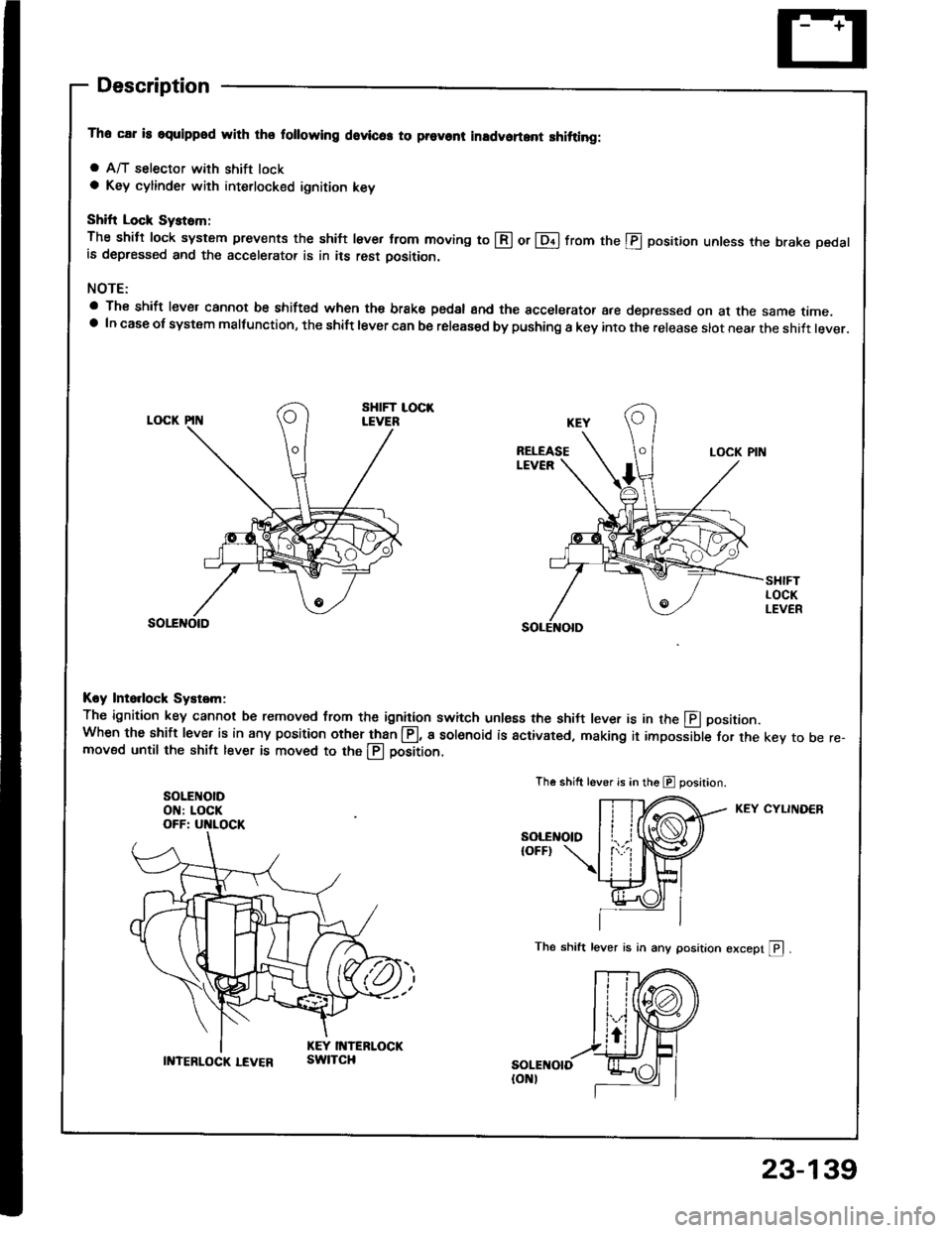
Descraption
The car is squippod with thq following dovlc6. to prevont inadvoft.nt shitting:
a A/T selector with shift locka Key cylinder with interlocked ignition key
Shift Lock Syst6m;
The shitt lock system prevents the shift lever from moving to @ or lDil from the @ position unless the brake pedalis depressed and the accelerator is in its rest oosition.
NOTE:
a The shift lever cannot be shifted when the brake pedsl and the accelerator are depressed on at the same time.a In case ot system malfunction, the shift lever can be released by pushing a key into the release slot near the shift lever.
Koy Ints.lock Systsm:
The ignition key cannot be removed from the ignition switch unless the shil-t lever is in the E positionWhen the shift lever is in any position other than @, a sol€noid is activated, making it impossible for the key to be re-moved until the shift lever is moved to the llj position.
SOLEI{OIDON: LOCKOFF: UNLOCK
Th€ shift lever is in the E position.
KEY CYLINDER
The shift lever is in any position except pl .
II{TERLOCK LEVERswtTcH
23-139