1994 HONDA INTEGRA brake
[x] Cancel search: brakePage 996 of 1413

8. Remove the carpet by sliding it rearward.
V : Cllp loc6tions
AV : Clip, 3B>: Clip, 1
FASTENERS
:ft
r,,-,
Hatchback
CARPET
Ssdan
FASTENERS
SILL MOLDINGREAR CONSOLEBRACKETSILL MOLDING
Installation is the reverse of the removal procedure.
NOTE:
a Take care not to damage, wrinkle or twist the
carpet.
a Make sure the seat harness is routed correctly.a Slip the slits in the carpet over the rear console
bracket.
REAR CONSOLEBRACKET
a Reattach the @ cut area of the carpet {see page
20-126). as tollows.
- 1) Clean the back of the carpet with a sponge
damoened in alcohol.
Attach the fasteners to the edge of the car,
pet with double-faced adhesive tape.
FASTENERS
-2) Attach the other tastener. as shown.
FASTENERS
CARPET
-3) Align the carpet with the fastener,
press the carpet down securely.
then
CARPET
Reattach the cut area under the parking brake
lever and (9 cut area (see page 20-126) with wire
ties, as shown.
Cut otf.
WIRE TIE
a lf necessary, replace any damaged clips.
FASTENER
SLIT
20-127
Page 998 of 1413

3.Remove the rear console,
NOTE:
a Lift up the parking brake lever.
a Oetach the hooks by lifting the front ot the rear
console and sliding it rearward.
Remove the sshtrsy and front console panel.
> : Scrow locatlon3, 2
Diaconn€ct the connector.
4.
l
5. Remove the trim ring, then remov€ th€ consolepanel.
NOTE:
a Take cafe not to scratch the selecter l6ver 8ndA/T gear position indicator panel.
a Remove the shiJt lever knob (M/T).
A : Cllp, hook loc.tions
AA : Clip, 2 BA : Cllp, 2 CA : Hook, 2
SHIFT I.EVERKNOB
CONSOLE PANEL
IM/TI
TRIM RI'{G
"onroar€
,"Hr"t z{o$
co soLE
POStTtONSELECTERLEVEBINDICATOR PANEL
6. Remove the screws.
> : Screw locationr, 4
6bo'' I:./
20-129
Page 999 of 1413

Front and Rear Consoles
Replacement (cont'd)
7. Remove the Jront console as shown.
NOTE: Wrsp the selecter lever and A/T gear posi-
tion indicator psnel with a shop towel to prevent
damage.
20-130
8. It necessary, disassemble the Jront and rear
consoles.
: Scrow locations, 5
Ai
_Y_)
CONSOLE PANEL (M�TI
SHIFT LEVERBOOT (M/TI
: Scraw locations, I
AI
Y,/
REAR CONSOLE
PARKING BRAKECOVER
COVER SETPLATE
9. Installation is the reverse of the removal procedure.
CONSOLE
ARMREST
cof{solE Box
Page 1015 of 1413

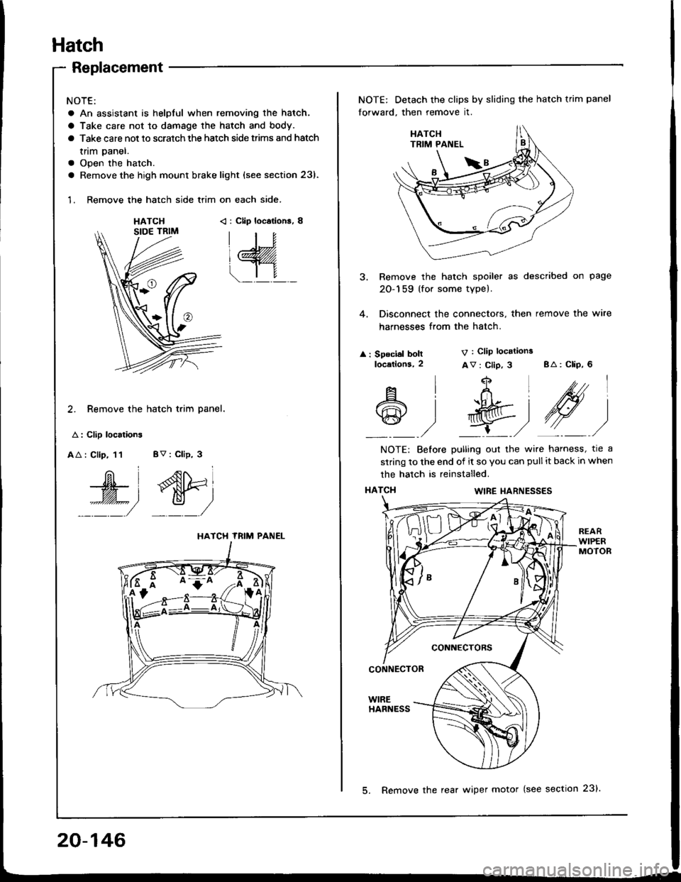
Hatch
Replacement
NOTE:
a An assistant is helpful when removing the hatch.
a Take care not to damage the hatch and body.
a Take care not to scratch the hatch side trims and hatch
tnm paner.
a Open the hatch.
a Remove the high mount brake light {see section 23).
1. Remove the hatch side trim on each side.
HATCH< : Clip locations, 8
2. Remove the hatch trim panel.
A : Clip localions
AA : Clip, 11 BV : Clip, 3
W', dtri
::::/ _:_/
HATCH TRIM PANEL
NOTE: Detach the clips by sliding the hatch trim panel
forward, then remove it.
3. Remove the hatch spoiler as described on page
20-159 (for some type).
4. Disconnect the connectors, then remove the wire
harnesses from the hatch.
: Speclal boltlocetlons,2
V : Clip locations
Av : Clip, 3 BA: CliP, 6
4
t+Ltfrl
l'R@t
,/ L,/
A
@
l
)
NOTE: Before pulling out the wire harness, tre a
strinq to the end of it so you can pull it back in when
the hatch is reinstalled.
HATCI{WIRE I{ARNESSES
CONNECTORS
CONNECTOR
WIREHARNESS
20-146
5. Remove the rear wiper motor (see section 23).
Page 1059 of 1413

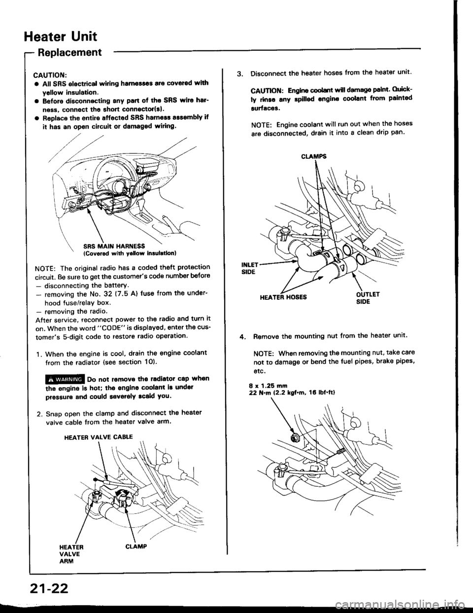
Heater Unit
Replacement
CAUTION:
a All SRS electrical witing hame$os are covoed wlth
yollow insulation.
a Before disconnecting any patt of tho SRS wito har-
neas, connect tha shott connoctol(s|.
a Roplaco th€ enlire sffacted SRS harnosr a$smbly if
it has an opon cilcult or dsmaged wiring.
NOTE: The original radio h8s a coded theft protection
circuit. Be sure to get the customer's code number betors
- disconnecting the bafterY.
- removing the No. 32 (7.5 A) fuse from th€ under-
hood tuse/relav box.- removing the radio
After service. teconnect power to the radio and turn it
on, when the word "CODE" is displayed, enter the cus-
tomer's 5-digit code to restore radio operation.
1. When the engine is cool, dtain the engine coolant
from the radiator (see section 1O).
@@ oo not lomove tho radiator cap whan
the ongine is hol; tha ongino coolant is undot
pressure and could a€voralY tcald you.
2. Snap open the clamp and disconnect the heater
valve cable from the heater valve arm.
HEATER VALVE CABLE
21-22
CLAMFS
3. Disconnect the heater hoses from the heater unit'
CAUTIOII: Engino coobnt will damago paint. orick-
ly dnse any rpilled engine coolant from paintod
surfac63.
NOTE: Engine coolant will tun out when the hoses
are disconnected, drain it into a clean drip pan'
HEATER HOSES
Remove the mounting nut from the heater unit.
NOTE: When removing the mounting nut, take care
not to damage or bend the fuel pipes, brake pipes,
etc.
8 r 1,25 rn|n22 N.m 12.2 kgt.m, tO lbf'ftl
4.
Page 1107 of 1413

Electrical
Special Tools
Troubleshooting
Tips and Precautions ................................ 23-3Five-stop Tloubleshooting ..............,...-..-... Z3-sSchematic Symbols ................................_. 23-6wire Color Cod€s ..................................... 23-6Relay and Control Unit Locations
Engine Compartment .........,............ ... --. 23-7Dsshboard and Door ..,,......................... 23-gDashboard and Floor ............................. 23-t OOuaner Panel .....-.....23-12Connector ldentification and WireHarness Routing ........ 23-i 3
Index to Circuits and Systems
Airbag ............... ...-..-... 2g-26sAir Conditioning ....,.. Section 2lAltelnator ......_.............. 23-99Anti-lock Brake Systsm (ABS) Section 19Automatic Transmission Section 14Battery .............. .......... 23-66Chafging System ........... 23-98rCigalstte Lighter .....................-...-......-..-.. Z3-2O4Cfock ................. ..........23-197rcruise Controf .......--..-... 23-242Distributor .................... 23-87Fan Controls ................. 23-1ogFuel and Emissions ... Section 1i*Fuses
Under-dash Fuse/Relay Box ................... 23-48Undor-hood ABS Fuse/Retay Box ............ 23-51Under-hood Fuse/Relay Box,.................. 23-52rGauges
Engine Coolant Temperature {ECT)Gauge ................ ..23-126Fuef cauge ............... 2g-123'Gauge Assembly ....--.23-113Speedometer .....-...,,. 23-114Tachometer .....,.....-.. 23-114Ground Distribution ........ 23-60Heater ,,,........,.... ..... Section 2lrHorn ................. ........... 23-199*fgnition Switch ............. 23-70fgnition Syst6m .......-..-.. 23-A7lgnition Timing .............. 23-89Indicator Lights"A/T Gear Position .............. ................... 23-1 32B1ak6 System ...,..,..-.23-127Engine Oil Pressura .............................. _ 23-1 51Low Fuel ............ ......23-125Malfunction Indicator Lamp {MlL} ...,,. Section I l
tfnteglated Control Unit ...29-144*lnterlock System ...................................... 23-1 3gLights, Exteriol
Back-up Lights ........... 23-179Brake Lights .............. 23-t8ltDaytime Running Lights {Csnada} ........... 23-156Front Palking Lights ............................. 23-1 65Flont Side Marker Lights ....................... 23-165Front Turn Signal Lights ........................ 23-1 65*Hazard Warning Lights .........................- 2g-1A4Headlights ................. 23-t6tLicense Plate Lights .............................. 23-1 69Taillights(Harchback) .......... 23-166
{Sedan) .............. .. 23-167Lights. Inteliol
Cargo Area Light {Hatchback) ...... -.. -.. -... 23-177Ceifing Light ........-..-.23-175
Dash Lights Blightness Controt .............. 23-t70Glove Box Lighr ................................... 23-1 69Spotfighr ............ ....-.23-174Trunk Light (Sedanl ............... .............. - 23.-177*Lighting Sysrem .......-.-... 23-152:Moonroof ,,.,.......,..,,,,,.-.23-211PGM-FI Systom ........ S€crion 11Power Distribution .,.-..--..23-54Power Door Locks .............,,..................... 23-233Power Mirors ..,..,....-...- 23-216Power Relays ...........,..... 23-68Power Windows ............ 29-222*Rear Window Defogger ........,... ..........,..... - 23-20,6Reminder Systems
Key-in Remindel System ....,.............,.... 23-1 50Lights-on Reminder System ................... 23-l 5f*Maintenance Reminder system ..,,.... -.. - -. 23-.1 2gSeat Belt Reminder System ..................- 23-125*Side Markel/Turn Signal/Hazard
Ffasher System .,..,..-.23.-1A4Spark Pfugs .........-...-..... 23-97Starting System ....,,.....-. 23-73*Stereo Sound System ...,.......................,,.. 23-l gg
Supplemental Restraint System {SRS} ......... 23-265Vehicfe Speed Sensor {VSS) .............--..-.... 23-122*Wiper/Washer Systom ...............--.........-..- Zg-254
rRead SRS pi€cautions on Page 23-271 betore workingin these areas.
-+
Page 1126 of 1413

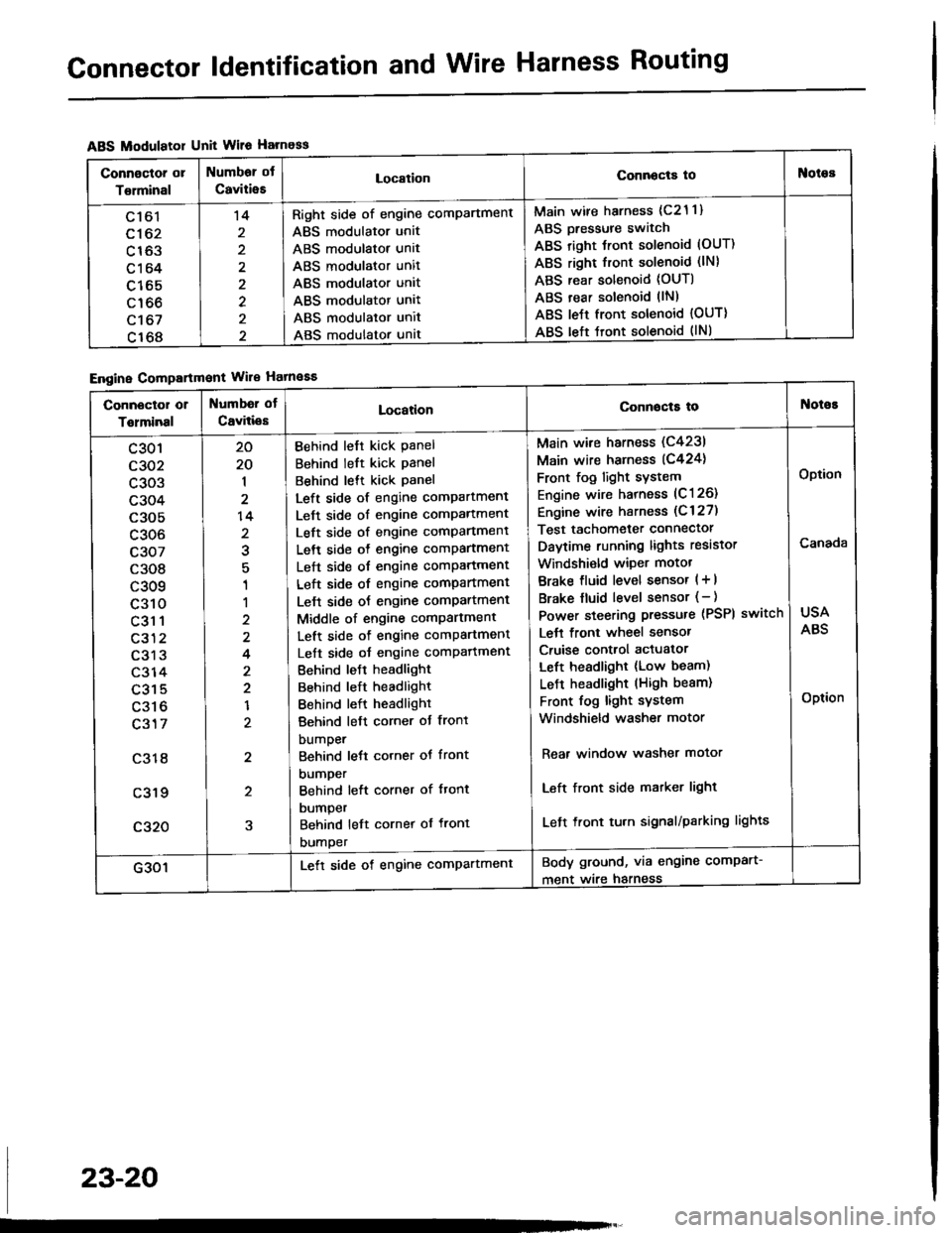
Connector ldentification and Wire Harness Routing
ABS Modulatol Unit Wile Harness
Engine Compartmont Wile Hatnaaa
Connoctor or
Torminal
Numbor ot
CaviiieELocationConnocta tooies
Ltol
c162
c163
c164
c165
c166
c't 67
c168
't4
2
2
Right side of engine comPartment
ABS modulator unit
ABS modulator unit
ABS modulator unit
ABS modulator unit
ABS modulator unit
ABS modulator unit
ABS modulator unat
Main wire harness (c21 1)
ABS Dressure switch
ABS right Jront solenoid (OUT)
ABS right front solenoid (lN)
ABS rear solenoid (OUT)
ABS rear solenoid llN)
ABS le{t front solenoid {OUT)
ABS left tront solenoid (lNl
Connector or
Tolminal
Numbd of
CaviliesLocationConnocta tot{oioE
c301
c302
c303
c304
c305
c306
c307
c308
c309
c310
c31 1
c312
c313
c314
c315
c316
c317
c318
c319
c320
20
20
1
2
14
2
1
1
2
4
2
2
1
2
2
5
Behind left kick Panel
Behind left kick panel
Behind lett kick Panel
Left side of engine compartment
Left side of engine comPartment
Left side of engine comPartment
Left side o{ engine comPartment
Left side of engine comPartment
Left side of engine compartment
Lelt side oJ engine comPartment
Middle of engine comPartment
Left side of engine comPartment
Left side oJ engine comPafiment
Behind leJt headlight
Behind left headlight
Behind left headlight
Behind left corner ot front
bumper
Behind lett corner ot front
DUmper
Behind left corner of ftont
DUmper
Behind left cornet of front
DUmper
Main wire harness (C4231
Main wire harness (C424)
Front fog light sYstem
Engine wire harness (C126)
Engine wire harness (C 127)
Test tachometer connector
Daytime running lights resistor
Windshi€ld wiper motot
Brake fluid level sensor ( + |
Brake fluid level sensor (- )
Power steering pressure (PSPI
Lett front wheel sensor
Cruise control actuator
Left headlight (Low beam)
LeJ-t headlight (High beam)
Front fog light system
Windshield washer motor
switch
Rear window washer motor
Left front side matker light
Left front tu.n signal/parking lights
USA
ABS
Option
Canada
Option
G301Lett side of engine comPartmentBody ground, via engine comPart-
ment wire harness
23-20
Page 1132 of 1413

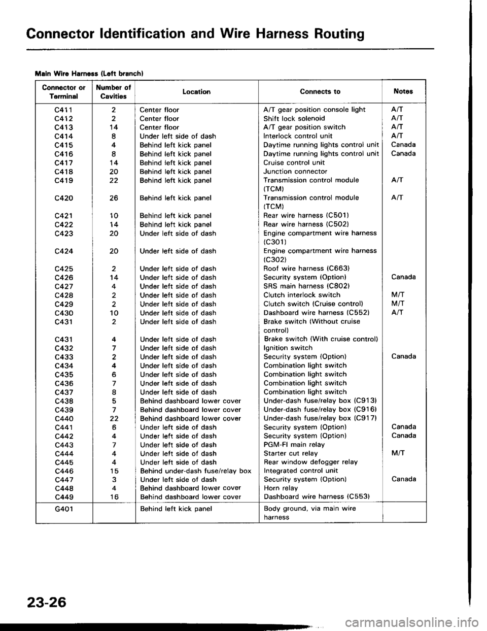
Connector ldentification and Wire Harness Routing
Msin Wiie Harness (Left branch)
Connector or
Terminal
Numbel ot
CavitiesLocationConnects toNotes
c411
c412
c413
c414
c415
c416
c4'17
c418
c419
c420
c42'l
c423
c424
c425
c426
c427
c42A
c429
c430
c431
c43l
c432
c433
c434
c435
c436
c437
c438
c439
c440
c44'l
c442
c443
c444
c445
c446
c447
c448
c449
26
10
20
20
14
8
4
I
14
20
22
't4
4
2
10
4
7
4
o
7
I
7
22
6
4
7
4
15
to
Center floor
Center floor
Center floor
Under left side ot dash
Behind left kick panel
Behind left kick panel
Behind left kick panel
Behind left kick panel
Behind left kick panel
Behind left kick panel
Behind left kick panel
Behind left kick panel
Under left side of dash
Under left side of dash
Under lett side of dash
Under left side ot dash
Under lett side of dash
Under lett side of dash
Under lett side of dash
Under lett side of dash
Under lett side ot dash
Under left side of dash
Under left side ol dash
Under left side of dash
Under left side of dash
Under left side of dash
Under left side of dash
Under left side of dash
Behind dashboard lower cover
Behind dashboard lower cover
Behind dashboard lower cover
Under left side of dash
Under left side of dash
Under left side of dash
Under lett side of dash
Under left side of dash
Behind under-dash fuse/relay box
Under left side ot dash
Behind dashboard lower cover
Behind dashboard lower cover
A/T gear position console light
Shift lock solenoid
A/T gear position switch
Interlock control unit
Daytime running lights control unit
Daytime running lights control unil
Cruise control unit
Junction connector
Transmission control module
(TCM)
Transmission controi module
{TCM)
Rear wire harness (C501)
Rear wire harness {C502)
Engine compartment wire harness
(c301)
Engine compartment wire harness
(c302)
Roof wire harness (C663)
Security system (Option)
SRS main harness (C802)
Clutch interlock switch
Clutch switch (Cruise control)
Dashboard wire harness (C552)
Brake switch (Without cruise
control)
Brake switch (With cruise control)
lgnition switch
Security system (Option)
Combination light switch
Combination light switch
Combination light switch
Combination light switch
Under-dash fuse/relay box {C9131
Under-dash fuse/relay box {C9161
Underdash tuse/relay box (C9'l 7l
Security system (Option)
Security system {Option)
PGM-FI main relay
Starter cut relay
Rear window defoqger relay
Integrated cont.ol unit
Security system {Option)
Horn relay
Dashboard wire harness (C553)
Afi
AiT
Afi
Afi
Canada
Canada
Arf
An
Canada
Canada
M/T
M/T
Atr
Canada
Canada
M/T
Canada
G401Behind left kick panelBody ground, via main wire
harness
23-26