1994 HONDA INTEGRA Stereo circuit
[x] Cancel search: Stereo circuitPage 1001 of 1413
Dashboard
Component Removal/lnstallation (cont'dl
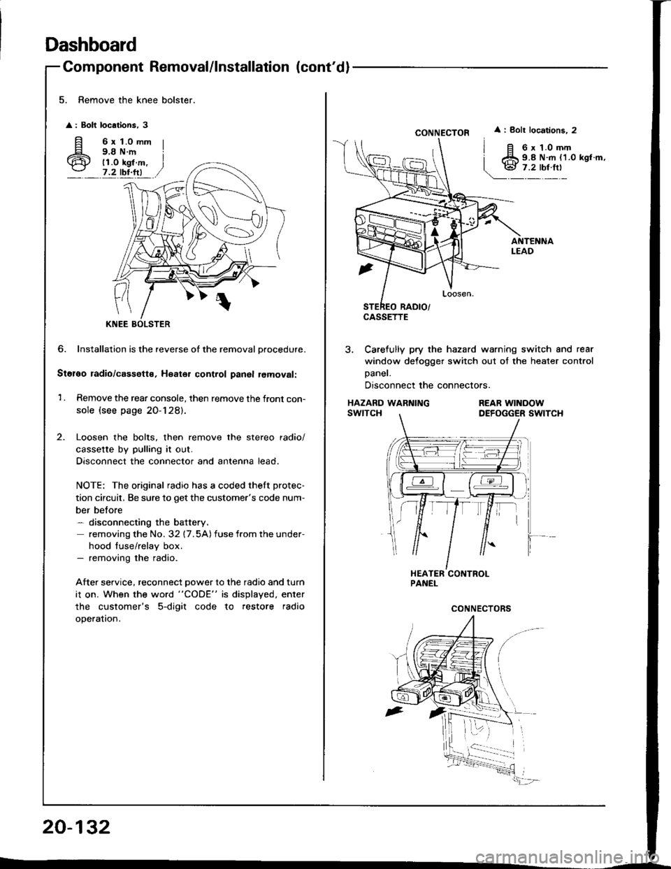
5. Remove the knee bolster.
: Bolt locations, 3
fi 6rt.omm
6 i;i'i#.,7.2 tbr.ftl
?
KNEE
6. Installation is the reverse of the removal Drocedure.
Stol€o radio/cassette, Heater control panal removal:
1 . Remove the rear console, then remove the front con-
sole (see page 20-128).
Loosen the bolts, then remove the stereo radio/
cassette by pulling it out.
Disconnect the connector and antenna lead.
NOTE: The original radio has a coded theft protec-
tion circuit, Be sure to get the customer's code num-
ber belore- disconnecting the battery.
removing the No. 32 17.5A) fuse from the under-
hood fuse/relay box.- removing the radio.
After service, reconnect power to the radio and turn
i1 on. When the word "CODE" is displayed. enter
the customer's 5-digit code to restore radio
operation.
20-132
CONNECTOR
CASSETTE
i Bolt locations. 2
6 x 1.0 mm9.8 N.m {1.0 kgl.m,
3, Carefully pry the hazard warning switch and rear
window defogger switch out of the heater control
Daner.
Disconnect the connectors.
HAZARD WARNINGswtTcHREAR WINOOWDEFOGGER SWITCH
Page 1107 of 1413

Electrical
Special Tools
Troubleshooting
Tips and Precautions ................................ 23-3Five-stop Tloubleshooting ..............,...-..-... Z3-sSchematic Symbols ................................_. 23-6wire Color Cod€s ..................................... 23-6Relay and Control Unit Locations
Engine Compartment .........,............ ... --. 23-7Dsshboard and Door ..,,......................... 23-gDashboard and Floor ............................. 23-t OOuaner Panel .....-.....23-12Connector ldentification and WireHarness Routing ........ 23-i 3
Index to Circuits and Systems
Airbag ............... ...-..-... 2g-26sAir Conditioning ....,.. Section 2lAltelnator ......_.............. 23-99Anti-lock Brake Systsm (ABS) Section 19Automatic Transmission Section 14Battery .............. .......... 23-66Chafging System ........... 23-98rCigalstte Lighter .....................-...-......-..-.. Z3-2O4Cfock ................. ..........23-197rcruise Controf .......--..-... 23-242Distributor .................... 23-87Fan Controls ................. 23-1ogFuel and Emissions ... Section 1i*Fuses
Under-dash Fuse/Relay Box ................... 23-48Undor-hood ABS Fuse/Retay Box ............ 23-51Under-hood Fuse/Relay Box,.................. 23-52rGauges
Engine Coolant Temperature {ECT)Gauge ................ ..23-126Fuef cauge ............... 2g-123'Gauge Assembly ....--.23-113Speedometer .....-...,,. 23-114Tachometer .....,.....-.. 23-114Ground Distribution ........ 23-60Heater ,,,........,.... ..... Section 2lrHorn ................. ........... 23-199*fgnition Switch ............. 23-70fgnition Syst6m .......-..-.. 23-A7lgnition Timing .............. 23-89Indicator Lights"A/T Gear Position .............. ................... 23-1 32B1ak6 System ...,..,..-.23-127Engine Oil Pressura .............................. _ 23-1 51Low Fuel ............ ......23-125Malfunction Indicator Lamp {MlL} ...,,. Section I l
tfnteglated Control Unit ...29-144*lnterlock System ...................................... 23-1 3gLights, Exteriol
Back-up Lights ........... 23-179Brake Lights .............. 23-t8ltDaytime Running Lights {Csnada} ........... 23-156Front Palking Lights ............................. 23-1 65Flont Side Marker Lights ....................... 23-165Front Turn Signal Lights ........................ 23-1 65*Hazard Warning Lights .........................- 2g-1A4Headlights ................. 23-t6tLicense Plate Lights .............................. 23-1 69Taillights(Harchback) .......... 23-166
{Sedan) .............. .. 23-167Lights. Inteliol
Cargo Area Light {Hatchback) ...... -.. -.. -... 23-177Ceifing Light ........-..-.23-175
Dash Lights Blightness Controt .............. 23-t70Glove Box Lighr ................................... 23-1 69Spotfighr ............ ....-.23-174Trunk Light (Sedanl ............... .............. - 23.-177*Lighting Sysrem .......-.-... 23-152:Moonroof ,,.,.......,..,,,,,.-.23-211PGM-FI Systom ........ S€crion 11Power Distribution .,.-..--..23-54Power Door Locks .............,,..................... 23-233Power Mirors ..,..,....-...- 23-216Power Relays ...........,..... 23-68Power Windows ............ 29-222*Rear Window Defogger ........,... ..........,..... - 23-20,6Reminder Systems
Key-in Remindel System ....,.............,.... 23-1 50Lights-on Reminder System ................... 23-l 5f*Maintenance Reminder system ..,,.... -.. - -. 23-.1 2gSeat Belt Reminder System ..................- 23-125*Side Markel/Turn Signal/Hazard
Ffasher System .,..,..-.23.-1A4Spark Pfugs .........-...-..... 23-97Starting System ....,,.....-. 23-73*Stereo Sound System ...,.......................,,.. 23-l gg
Supplemental Restraint System {SRS} ......... 23-265Vehicfe Speed Sensor {VSS) .............--..-.... 23-122*Wiper/Washer Systom ...............--.........-..- Zg-254
rRead SRS pi€cautions on Page 23-271 betore workingin these areas.
-+
Page 1155 of 1413
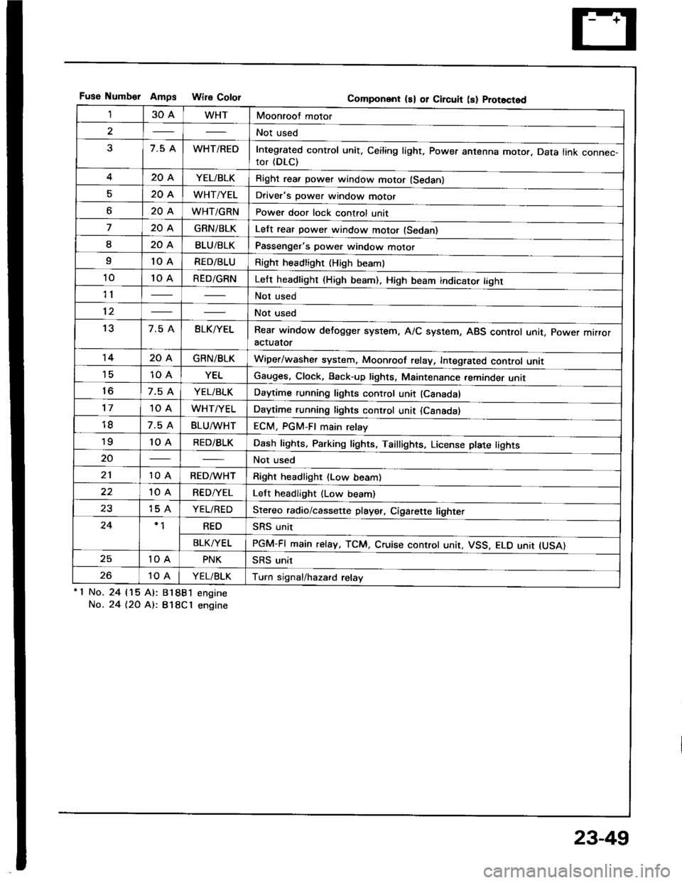
Fuse Numb€r AmDs Wire CololGomponent ls) or Circuit (s) Prot8cted
130AWHTMoonroof motor
2Not used
37.5 AWHT/REDIntegrated control unit, Ceiling light, Power antenna motor. Data link connec-tor (DLC)
420AYEL/BLKRight rea. power window motor (Sedan)
520AWHT/YELDriver's power window motor
o20AWHT/GRNPower door lock control unit
720AGRNiBLKLelt rear power window motor (Sedan)
I20ABLU/BLKPassenger's power window motor
I10 ARED/BLURight headlight {High beaml
1010 ARED/GRNLeft headlight (High beam). High beam indicato. tight
11Not used
12Not used
137.5 ABLK/YELRear window defogger system, A/C system, ABS control unit, power mrrroractuator
1420AGRN/BLKWiper/washer system, Moonroof relay, Integrated control unii'1510 AYELGauges, Clock, Back-up lights, Maintenance reminder unit
to7.5 AYEL/BLKDaytime running lights control unit (Canadal
1710 AWHT/YELDaytime running lights control unit (Csnada)
7.5 ABLU^tvHTECM, PGM-FI main relay'to10 ARED/BLKDash lights, Parking lights, Taillights, License plate tights
20Not used
2110 ARED/WHTRight headlight (Low beam)
10 ARED/YELLeft headlight (Low beam)
2315 AYEL/REDStereo radio/cassette player, Cigarette lighter
24REOSRS unit
BLK/YELPGM-FI main relay, TCM, Cruise controt unit, VSS, ELO unit IUSA)
2510 APNKSRS unit
2610 AYEL/BLKTurn signal/hazard relay'1 No.
No.
24 115 Al:
24 t2O At:.
81881 engine
B18Cl engine
23-49
Page 1294 of 1413
Stereo Sound System
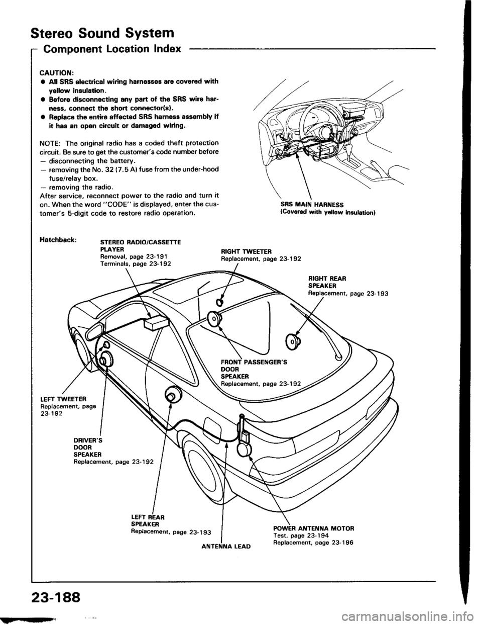
Component Location Index
LEFT TWEETERReplacement, page
23-192
DRIVER'SDOORSPEAKERRepfacement, page 23-192
CAUTION:
a All SRS el€ctrical wlring harneaseE are covered with
yallow insulation.
a Belore dbconnscting any part of the SRS wire har-
nass, connect tho short connector(sl.
a Replace tho entir6 affoctod SRS harn6ss assembly if
it has an opan circuit or damag6d widng.
NOTE: The original radio has a coded theft protection
circuit. Be sure to get the customet's code number belore- disconnecting the battery.- removing th€ No. 32 (7.5 A)tuse from the under-hood
fuse/relay box.- removing the radio.
After service, reconn€ct power to th€ radio and tutn it
on. When the word "CODE" is displaved, enter the cus-
tomer's 5-digit code to restore radio opelation.
Hatchback:STEBEO RADIO/CASSETTEPTAYERRemoval. paoe 23-191Terminals, page 23-192
SBS MAII{ I{ARI{ESS(Covor€d wirh y6llow in3ulationl
LEFTSPEAKER
RIGHT REARSPEAKERReplacement. page 23-193
ANTENNA MOTORTest, page 23-194
DOORSPEAKERRepfacement, page 23-192
23-188
!iltil;s'
Replacemenr. page 23-193
Replacement, page 23-196
Page 1296 of 1413
tlo.4lllo0Al No.39l50Al
SIER€O MOOCASSETTE N.AYER
Stereo Sound System
UNDER-HOOO FUSE i RETAY BOX
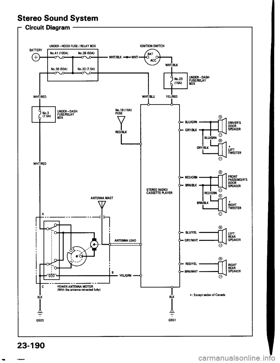
Circuit Diagram
UNDEN-DASHFUSENEIAY8ox
tGNtTOt{ SWTTCH
WHT/BI"K +WHT
No.l9ll0AlRJSE
AI{TE?{NA MAST
-L-fl
4
-fi1
.a'J
POWER AIT€NI{A MOTOFM_nh tho antanna ntrrct d fulvl
AMTEI{iIA ITAD
RIGI{TREARSPEAXER
23-190
| : Excoot !ad!n of Crnede
Page 1297 of 1413
Unit Removal
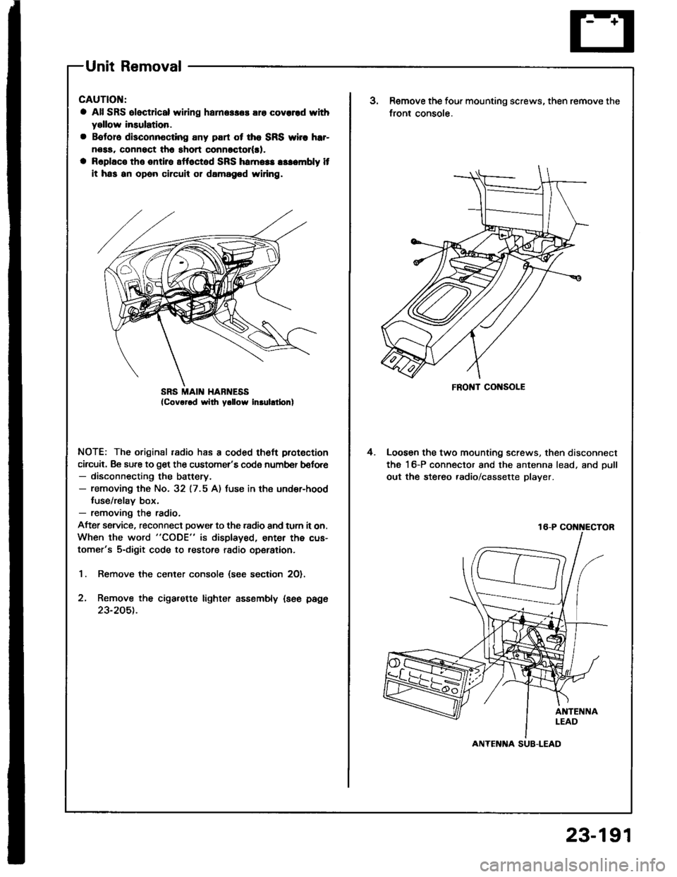
CAUTION:
a All SRS oloctrical wi ng harn.$.s ara covcrrd withyellow insulation.
a B€toro disconnocting any part ot tho SRS wirc hrr-
nosa, connsct tho short conn6ctol(rl.
a Raplaco the sntirs sttoctod SRS hamoas asacmbly it
it has an opon circuil 01 damagod widng.
NOTE: The original radio has a coded theft protection
circuit. Be sure to get the customer's code number b€lore- disconnecting the battery.- removing the No. 32 (7.5 A) fuse in the under-hood
fuse/relay box.- removing the radio.
After ssrvice, reconnect power to the radio and turn it on.
When the word "CODE" is displayed, enter the cus-
tomer's 5-digit code to restore radio operation.
1. Remove the center console (see section 2O).
2, Remove the cigarette lighter assembly {see page
23-205t.
SRS MAII{ HABNESSFRONT CONSOLE
3.Remove the four mounting screws, then remove the
front console.
Loosen the two mounting screws, then disconnect
the 16-P connector and the antenna lead, and oull
out the stereo .adio/cassette player.
4.
16-P COi{i{ECTOR
ANTENlTA SUB-LEAD
23-191
Page 1303 of 1413
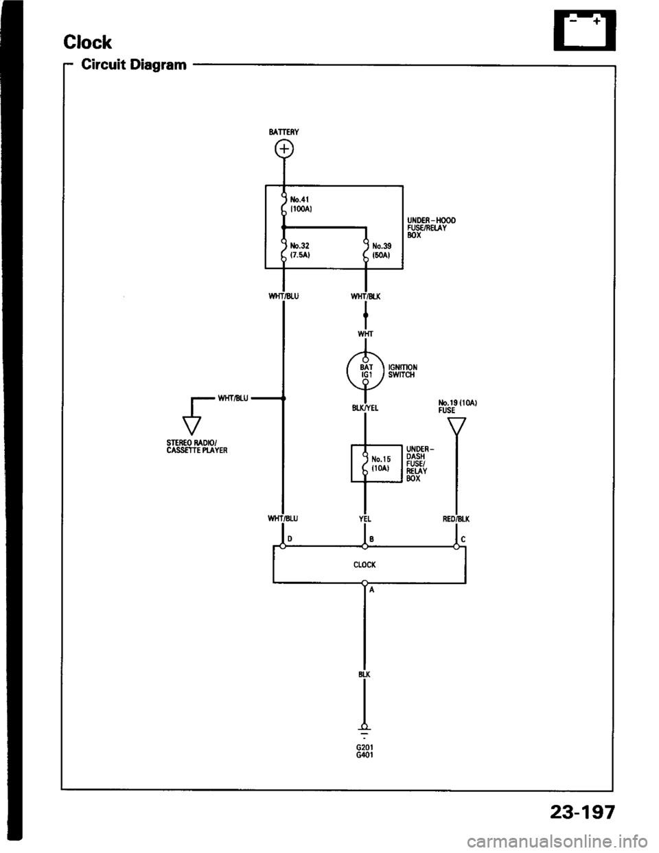
Circuit Diagram
VSTEREO RADIO/CASS€TIE PI-AYER
23-197