1994 HONDA INTEGRA hood release
[x] Cancel search: hood releasePage 40 of 1413

Lubrication Points
For the details ol lubrication points and type of lubricants to be spplied, reter to the illustrated index and various workprocedure (such as Assembly/Reassembly, Replacement, Overhaul, Instatlation, etc.) contained in each section.
No.LUBRICATION POII\ITSLUBRICAI\IT
IEngineAPI Service Grade: Use SG or SH "Energy Conserving
II" grade oil.
The oil container may also display the API Certifications€al shown below. Make sure it says'For GasolineEngines.'
SAE Viscosity; See chan below.
Transmission Manual
Automatic
API Service Grades: SF or SG
SAE Viscosity: 1O W-3O or 1O W-4O
Honda Premium Formula or DEXRON@ II
Automatic transmission fluid
3Brake line (lncludes Anti-lock brake linelBrake fluid DOT3 or DOT4
4Clutch lineBfake tluid DOT3 or DOT4
Power steering gearboxSteoring grease P/N 08733-BO7OE
Release fork (Manual transmission)Supe. High Temp Urea Grease (P/N O8798*9OO2)
8
Throttle wire end {Dashboard lower Danel holel
C.uise cont.ol actuatot wire end
{Dashboard lower Danel holel
Silicone grease
I
10'I '�l
12
13
14
15
to
17
18
Throttle cable end (Throttle linkl
Cruise control actuator cable end lActuator link)
Brake master cvlinder Dushrod
Clutch master cylinder pushrod
Engine hood hinges and engine hood latch
Batte.v terminals
Fuel fill lid
Hatch hinges or trunk hinges
Door hinges. upper and lowet
Door oDen detent
.Multi-purpose grease
19Rear brake calioersRust-p,eventive agant
20Power steering systemHonda power steering tluid-V
21Air conditioning compressorRetrigerant oit ND-otL8 |PlN 38899-pR7-A01)(For Relrigerant: HFC-134a (R-134a))
-20 0 20 r}() 60 ao loooF
-30 -20 -'to o 10 20 30 40"c
Recolnmendod engine oilEngine oil viscosity torambient tgmpelalure rangos
API CERTIFICATION SEAL
Page 284 of 1413

- ldle Speed Setting
Inspoction/Adiustment
NOTE:
a When the idle speed set, check the following items:
- The MIL has not been reported on.- lgnition timing- Spark plugs- Air cleaner- PCV svstem
a (Canada) Pullthe parking brake lever up. Stan the en-
gine, then check that the headlights are off.
1 Start the engine. Hold the engine at 3,000 rpm with
no load (A/T in S or @ position, M/T in neutral)
until the radiator tan comes on, then let it idle.
2. Connect a tachometer.
3. Disconnect the 2P connectot trom the ldle Air Con-
trol {lAC) valve.
Start the engine with the sccelerator pedal slightly
depressed. Stabilize the rpm at 1 ,OOO, then slowly
release the pedal until the engine idles.
Check idling in no-load conditions: headlights, blower
fan, rear defogger, radiator fan, and ai. conditioner
are not operatrng.
ldl€ spood should bo;
81881 ongino:
MlT48O ! 50 rym
An48O I 50 rpm
lin@or@oosition)
818C7 engine:48O ! 50 rym
Adjust the idle speed, if necessary, by turnmg the
idle adiusting screw.
NOTE: After adiust the idle speed in this step, check
the ignition timing (see section 231.
lf it is out ot spec. go back to step 4.
4.
e
Turn the ignition switch OFF.
Reconnect the 2P connector on the IAC valve, then
remove the BACK UP (7.5 A) fuse in the under-hood
tuse/relav box for 1O seconds to reset the ECM.
Restart 8nd idle the engine with no-load conditions
for one minute, then check the idle speed.
NOTE: (Canada) Pull the parking brake lever up.
Start the engine, then check that the headlights ate
off.
ldlo speed should be;
81881 ongino:
MTf75O ! 50 rpm
AIT75O t 50 rpm
(in[]or@positionl
818C1 engine: 750 1 50 rpm
(cont'd)
11-95
Page 960 of 1413

Interior Trim
Replacement
a W€al gloves to remove and installth€ trim and panols.a When prying with a flat tip screwd.ivor. wrap it withprotective tap€ to prevent damaga.
NOTE: Take care not to bend or scratch the trim andDanels.
Kick panel/Front pillar trim removal:
l. Remove the kick Danel.
< : Clip locations
A< | Cllp, 1 B< : Ctip, 1 CV : C[p, 1
Jtl,Ml*
U ry-ry
NOTE: Remove the driver's kick panel while pullingthe hood release handle.
KICK PANEL
Pull the door trim back, then remove the front oillarrflm.
< : Clip locations, 4
lnstallation is the reverse of the removal procedure.
NOTE: lf necessary, .eplace any damaged clips.
FRONT PILLAR
20-91
Hatchback
Rear trim panet/Side trim panel/Ouarter pillar trim p-l16moval:
1. Open the hatch.
2. Remove the .ear shelt.
Remove the rear seat (see page 20-'l08).
Remove the trunk mat and spare tire lid.4.
ao..t dr
REAR SHELF
REAR SHELF
TRUNK MAT
SPARE TIRE LID
Page 1021 of 1413

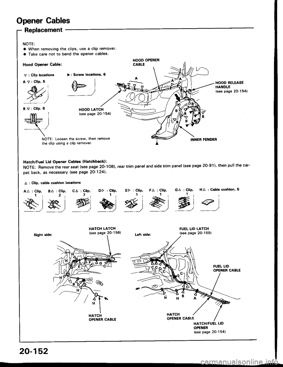
Opener Cables
NOTE:
a When removing the clips, use a clip remover.
a Take care not to bend the opener cables.
Replacement
Hood Opener Cable:
v : Clip location.
Av:CllP,5
M)
HOOD OPENERCABLE
> : Scrow locrtions, 6
Otr" I
:_ _)
HOOD RELEASEHAI{DLE(se€ page 20-1 54)
Bv:Clip.6HOOD LATCH(see page 20"154)E\I____lEt- L:=r
,/- -\-
NOTE: Loosen the screw, then remove
the clip using a clip remover.INNER FENDER
HA : C.bl6 cushlon, 5GA : Clip,
Wt
DD : Cllp, Etr : Cllp,1, I,
e&r @)9)
HATCH LATCH
lsee page 2O-1 56)Loft 3ido:
FUEL LID LATCH
lsse page 2O-155)
Hatch/Fuol Lid Oponer Cabls lHatchback):
NOTE: Remove the rear seat (see page 20-108), rear trim pan€l and side trim panel (see page 2O-91), then pull thecar-
Det back. as necessary lsee page 20-124).
A : Clip, csblo cushion location3
AA : Clip, 8A : Clip, CA : CliP,i r 2, 7,
s-,$, g,
FA : Cllp,
s,l
Right sids:
HATCHOPENER CABLE
HATCH/FUEL LID
OPENER{see page 2O-'l 54)
20-152
HATCH
Page 1023 of 1413

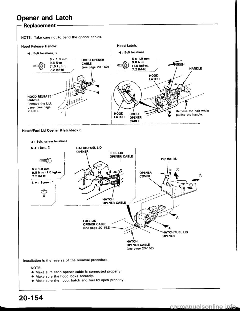
Opener and Latch
Replacement
NOTE: Take care not to bend the opener cables.
Hood Relsase Handle:
< i Bolt locations, 2
Hood Latch:
< : Bolt locations
6 x 1.0 mm9.8Nm(1.0 kgl m,7.2 tbl.lrl
HOOD OPENERCABLE(see page 20'152)
6 x 'l.O mm9.8Nm11.0 kgl m,7 .2 tbt ftl,/HANDLE
HOODLATCH
HOOD RELEASEHANOLERemove the kickpanel (see page
20-91).HOODLATCHHOODOPENERCABLE
Remove the bolt whilepulling the handle.
I
Hatch/Fuel Lid Opener lHatchback):
< : Bolt, sclow locations
A
6' I
vl
/
HATCHiFUEL LID
OPENER
6 x 1.0 mm
9.8 N m 11.0 kgl'm,
7.2 tbl.fr)
FUEL LIDOPENER CAELE
lnstallation is the reverse of the removal procedure'
NOTE:
a Make sure each opener cable is connected properly
a Make sure the hood locks securely
a Make sure the hood, hatch and fuel lid open properly.
the
J'o
t
OPENERCOVER
HATCHOPENER CABLE(see page 20-152)
@
t-
20-154
Page 1109 of 1413

Troubleshooting
Tips and Precautions
Before Troubloshooting
a Check applicable fuses in the appropriate fuse/relay
DOX.
a Check the battery for damage, state of charge, and
clean and tight connections.a Check the alternator belt tension.
CAUTION:
a Do not quick-charg€ a battery unless the batteryground cabla has be€n disconnoctsd. oth€rwisoyou will damage the alternator diodss.a Do not att6mpt to crank the engine with the bat-tery ground cable loosely connectsd or you will se-vorsly damag€ tho widng.
a The original radio has a codod thatt plotection ci.-cuit. Be sul€ to got tho customor's code numbet
before- disconnecting th€ battery.- lomoving tho No. 32 (7.5 Al tuso f.om the
under-hood tuse/lelay box.- removing tho radio.
Aflor s€lvic€. reconn€ct powet to tho radio and
turn it on. Whon the word "CODE" is displayed,
€nt€l the customer'E s-digit codo to .astore ladio
operation.
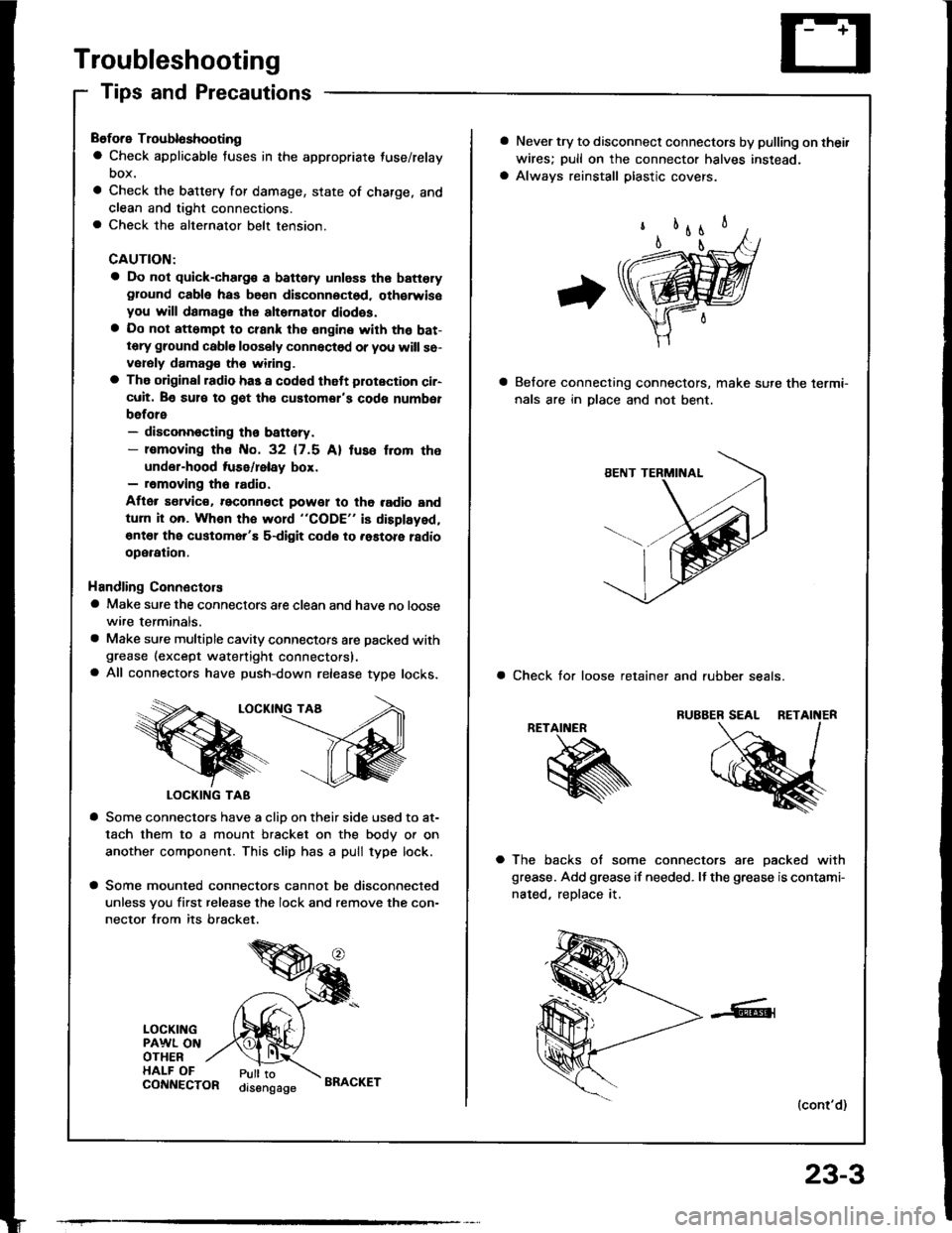
Handling Connectors
a Make sure the connectors are clean and have no loose
wire terminals.
a Make sure multiple cavity connectots are packed withgrease (except watertight connectors).a All connectors have push-down release type locks.
LOCKII{G TAA
LOCKING TAB
a Some connectors have a clio on their side used to at-
tach them to a mount bracket on the body or on
another component. This clip has a pull type lock.
a Some mounted connectors cannot be disconnected
unless you first release the lock and remove the con-
nector from its bracket.
LOCKINGPAWL ONOTHERHALF OFPull toorsengageCONNECTORBRACKET
23-3
a Never try to disconnect connectors by pulling on thei.
wires; pull on the connector halves instead.
a Always reinstall plastic covers.
Belore connecting connectors, make sure the lermi-
nals are in Dlace and not bent.
a Check tor loose retainer and rubber seals.
RETAINER
a The backs of some connectors are oacked with
grease. Add grease if needed. It the grease is contami-
nated, reDlace it.
(cont'd)
Page 1353 of 1413

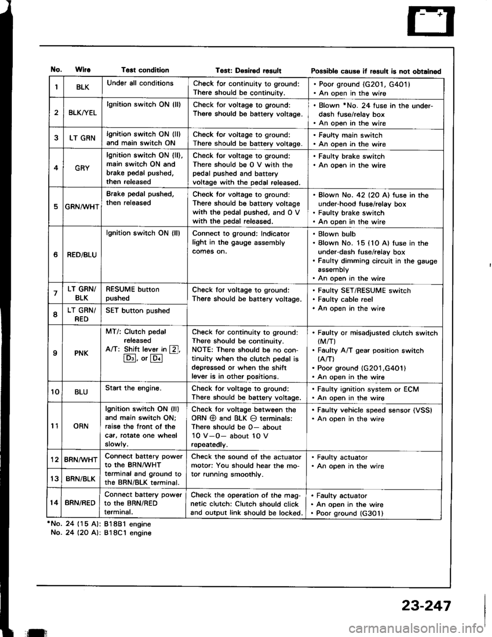
tlo.WlfeTost condition
*No. 24 (15 Al: 81881 engine
No.24 l2O A): 818C1 engine
Tost: Desired rosultPossibl6 caus€ it losult is not obtained
IBLKUnder all conditionsCheck for continuity to ground:
There should be continuitv.
. Poor ground (G201, G4011. An open in the wire
2BLKryEL
lgnition switch ON (ll)Check for voltage to ground:
There should be battery voltage.
. Blown rNo. 24 fuse in the under-
dash fuse/relay box. An open in the wire
5LT GRNlgnition switch ON (ll)
and main switch ON
Check for voltage to ground:
There should be battery volt€ge.
. Faulty main switch. An open in the wire
4GRY
lgnition switch ON lll),main switch ON and
brake pedal pushed,
then released
Check for voltage to g,ound;
There should be O V with thepedal pushed and battery
voltage with the pedal released,
. Faulty brake switch. An open in the wire
GRN/wHT
Brake pedal push€d,
then r€leased
Check tof voltage to ground:
There should be battery voltage
with the pedal pushed, and O V
with the Dedal released.
Blown No. 42 l2O Al tuse in the
under-hood fuse/relay box
Faulty brake switch
An open in the wire
6RED/BLU
lgnition switch ON (ll)Connect to ground; Indicator
light in the gauge assembly
comes on.
Blown bulb
Blown No. 15 (10 A) fuse in the
under-dash fuse/relay box
Faulty dimming circuit in the gauge
assembly
An open in the wire
7LT GRN/
BLK
RESUME button
pushedCheck for voltage to ground:
There should be battery voltage.
Faulty SET/RESUME switch
Faulty cable reel
An open in the wire6LT GRN/
RED
SET button pushed
qPNK
MT/: Clurch pedal
released
A/T: Shift l€ver in [Zl,
lD:I, or lE.l
-
Check for continuity to ground:
There should be continuity.
NOTE: There should be no con-
tinuity when the clutch pedal is
depressed or when the shift
lever is in other positions.
Faulty or misadiusted clutch switch(M/T)
Faulty A/T gear position switch(A/T)
Poor ground (G201 ,G4O1)An open in the wire
10BLUStart the engine.Chsck for voltage to ground:
There should be battery voltage.
. Faulty ignition system or ECM. An open in the wire
11ORN
lgnition switch ON (ll)
and main switch ON;
rsise the front of the
car, rotat€ one wheel
slowly.
Check Jor voltage between the
ORN @ and BLK O terminals:
There should be O- about
10 V-O- about 1O V
repeatedly.
. Faulty vehicle speed sensor (VSSI. An oDen in the wire
'128RN/WHTConnect battery power
to the BRN/WHT
terminal and ground to
the BRN/BLK terminal.
Check the sound of the actuator
motor: You should hear the mo-
tor running smoothly.
. Faulty actuator. An opsn in the wire
13BRN/BLK
14BRN/RED
Connect battery power
to the BRN/RED
terminal.
Check the operation of the mag-
netic clutch: Clutch should click
and output link should be locked.
Faulty actuator
An open in the wire
Poor ground (G3O 1)
il:
23-247