Page 424 of 1413

Description
Hydraulic Flow (cont'dl
@ or @ Position
1. lst Spe€d
The flow of fluid throuth the torque convener circuit is the same as in S Oosition.The line pressure ( 1 ) becomes line pressure (4) and it becomes the 1 st clutch pressure (1O). The I st ctutch pressure
is applied to the lst clutch and l st accumulator; consequently, the vehicle will move as the engine power is transmitted.The line pressure (1) becomes the modulator pressure (6) by the modulator valve and travels to 1-2 and 3-4 shift valves.
The 1-2 shift valve is moved to the right side because the shilt control solenoid valve A is turned off and B is turned
on by the TCM. This valve stops 2nd clutch pressure and power is not transmitted to the 2nd clutcn.Line pressu.e {4) also tlows to the seryo valve and line pressure (1 } also flows to throttle valve B.
NOTE:. When used, "left" or "right" indicates direction on the flowchart.. SOL-@: Shitt Control Solenoid Valve A. SOL-@:Shift Control Solenoid Valve B. SOL-O: Lock-up Control Solenoid Valve A. SOL-@: Lock-up Control Solenoid Valve B
14-32
I
Page 428 of 1413

Description
Hydraulic Flow (cont'd)
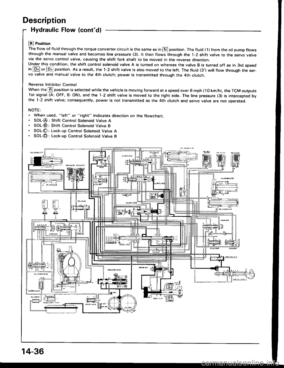
LEI Position
The flow ot fluid through the torque convener circuit is the same as in S position. The tluid ( 1 ) trom the oil pump flowsthrough the manual valve and becomes line pressure (31. lt then flows through the 1-2 shift valve to the servo varvevia the servo control valve, causing the shift tork shatt to be moved in the reverse direction.Under this condition, the shift control solenoid valve A is turned on whereas the valve B is turned ofJ as in 3rd speedin [Dil or lDs]l position. As a result, the 1-2 shift valve is also moved to the left. The ftuid (3'] will ftow through the ser-vo valve and manual valve to the 4th clutch; power is transmitted through the 4th clutch.
Reverse Inhibitor Control
When the @ position is selected while the vehicle is moving forward at a speed over 6 mph ( 1O km/h). the TCM outputs1st signal (A: OFF, B: ON), and the 1-2 shift valve is moved to the right side. The line pressure {3) is intercepted bvthe 1-2 shift valve; consequently, power is not transmitted as the 4th clutch and servo valve are not oDerareo.
NOTE:. When used, "lefl" ot "tight" indicates direction on the flowchart.. SOL-@: Shift Control Solenoid Valve A. SOL€: Shift Control Solenoid Valve B. SOL€: Lock-up Control Solenoid Vatve A. SOL-@: Lock-up Control Sotenoid Vatve B
14-36
Page 429 of 1413
Lll Position
The flow of fluid through the torque converter circuit is the same as in I position. The line pressure ( l ) becomes line
pressure (3) as it passes through the manual valve. Then line pressure (3) flows through the 1-2 shift valve to the servo
valve via the servo control valve. causing the shift fork shaft to be moved to the reverse position as in E position.
However. the hydraulic pressure is not supplied to the clutches. Power is not transmitted.
NOTE:. When used, "left" or "right" indicates direction on the flowchart.
. SOL-@: Shitt Control Solenoid Valve A
. SOL-@: Shift Control Solenoid Valve B
. SOL-O: Lock-up Control Solenoid Valve A
. SOL-O: Lock-up Control Solenoid Valve B
14-37
Page 430 of 1413
Description
Lock-up System
Lock-up Clutch
1. Operation (clutch on)
With the lock-up clutch on, the oil in the chamber between the torque convener cover and lock-up piston is discharged,and the converter oil exerts pressure through the piston against the converter cover. As a result, the converter turbineis locked on the converter cover firmly. The etfect is to bypass the converter, thereby placing the car in direct drive.
tpowefJlo-wl
The power tlows by way of:
Engine
I
Drive plate
I
Torque convener cover
I
Lock-up piston
I
Damper spring
I
Turbine
t
Mainshaft
TOROUE CONVERTERCOVER
LOCK-UP
TURBINE
To oil cooler
2. Operation (clutch off)
With the lock-up clutch off, the oil tlows in the reverse of CLUTCH ON. As a result, the lock-up piston is moved away
from the converter cover; that is, the torque converter lock-up is released.
Fowtttowl
Engine
I
Drive plate
I
Torque converter cover
Pump
I
Turbine
I
Mainshaft
OUTLET
t
,\
TURBINE
14-38
Page 431 of 1413

In E position in 2nd, 3rd and 4th, and @ position in 3rd, pressurized fluid is drained from the back of the torque con-
verter through an oil passage, causing the lock-up piston to be held against the torque converter cover. As this takes
place, the mainshaft rotates at the same speed as the engine crankshaft. Together with hydraulic control, the TCM op-
timized the timing ot the lock-up system. Under certain conditions, the lock-up clutch is applied during deceleration, in
3rd and 4th sDeed.
The lock-up system controls the range of lock-up according to lock-up control solenoid valves A and B, and throttle valve B.
When lock-up control solenoid valves A and B activate. modulator pressure changes. Lock-up control solenoid valves
A and B are mounted on the torque converter housing, and are controlled by the TCM.
NOTE:
When used, "left" or " tight" indicates direction on the tlowchart.
LOCK IJP COIITBOL
Solenoid valve
L""f."p "."aiti""\B
Lock-up OFFOFFOFF
Lock-up, slightONOFF
Lock-up, halfONON
Lock-up. fullONON
Lock-up
during decelerationONDuty operation
OFF -ON
LOCI( UP TIMII{G B VAIVE
{cont'd)
ott coot€R
14-39
Page 432 of 1413
Description
Lock-up System (cont'dl
No Lock-uo
The pressurized fluid regulated by the modulator works on both ends of the lock-up shift valve and on the left side ot
the lock-up control valve. Under this condition, the pressu.es working on both ends ol the lock-up shitt valve ate equal.
the shift valve is moved to the right side by the tension of the valve spring alone. The tluid from the oil pump will flow
through the left side of the lock-up clutch to the torque converter; i,e., the lock-up clutch is in OFF condition.
NOTE: When used. "left" or "right" indicates direction on the flowchart.
LOCK.UP CONTRO!
<- MOOULATOi PBfSSURE
LOCK.UP TIMI GAVALVE
14-40
Page 433 of 1413

{l
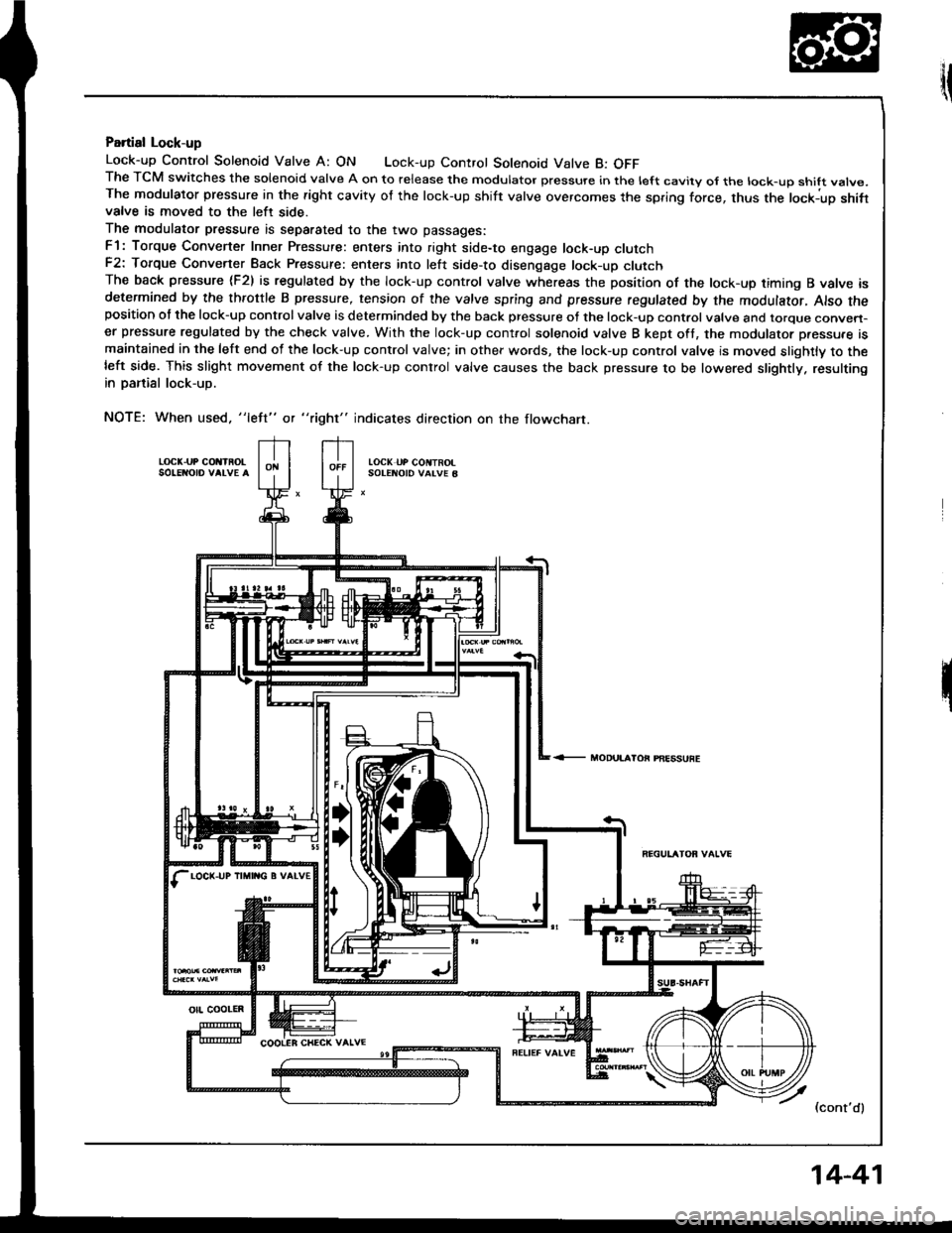
Partial Lock-up
Lock-up Control Solenoid Valve A: ON Lock-up Control Solenoid Valve B: OFFThe TCM switches the solenoid valve A on to release the modulator pressure in the left cavity ol the lock-up shift vatve.The modulator pressure in the right cavity of the lock-up shift valve overcomes the spring force, thus the lockiup shifivalve is moved to the left side.
The modulator pressure is separated to the two passages:
F1: Torque Converter Inner Pressure: enters into right side-to engage lock-up clutchF2: Torque Convener Back Pressure: enters into left side-to disenqage lock-up clutchThe back pressure (F2) is regulated by the lock-up control valve whereas the position of the lock-up timing B valve isdetermined by the throttle B pressure, tension of the valve spring and pressure regulated by the modulator, Also theposition of the lock-up control valve is determinded by the back pressure of the lock-up control valve and torque conven-er pressure regulated by the check valve. With the lock-up cont.ol solenoid valve B kept oft, the modulator p.essu.e ismaintained in the left end of the lock-up control valve; in other words, the lock-up control valve is moved slightly to theleft side. This slight movement of the lock-up conlrol valve causes the back pressure to be lowered slightly. resultingin panial lock-up.
NOTE: When used. "left" or "right" indicates direction on the flowchart.
LOCK.UP COIIIROLSO!ENO|o VALVE ALOCK UP COIITROISOTENOID VALVE B
<- MODUI.AIOi PAESSUFE
7 l.ont'al
LOCK-UP IIMII{G B VATV€
otl coolEn
14-41
Page 435 of 1413

Full Lock-uo
Lock-up Control Solenoid Valve A: ON Lock-up Control Solenoid Valve B: ON
When the vehicle speed fufther increases, the throttle B pressure is increased in accordance with the throttle opening.
The lock-up timing B valve overcomes the spring force and moves to the left side. Also, this valve closes the oil port
leading to the torque converter check valve.
Under this condition, the throttle B pressure working on the right end of the lock-up control valve becomes greater than
that on the left end (modulator pressure in the lelt end has already been released by the solenoid valve B); i.e., the lock-up
control valve is moved to the left. As this happens, the torque convener back pressure is released fully, causing the
lock-up clutch to be engaged fully.
NOTE: When used, "left" or "right" indicates direction on the tlowchart.
LOC( UP COi{TAO!toc( uP coNtnolSOIENOID VAIVE B
THRO]TIE A PFESSURE
PNESSUFE
FEGUTATOF VAIVE
LOCK-UP TIMIIIG B VALVE
(cont'd)
orl cootER
14-43