1994 HONDA INTEGRA torque
[x] Cancel search: torquePage 149 of 1413

ConnectingRod Bearings
ClearanceSelection
CAUTION: lf the codss are indeciphsrable bocause of
an accumulation of dirt and dust. do not scrub tham
with a wiro brush or scraper. Clean them only with sol-
vont or dotetgenl.
Connecting Rod Code Location
A number has been stamped on the side of each con-
necting rod as a code for the size of the big end. Use it,
and the letters stamped on the crank (codes for rod jour-
nal size), to choose the correct bearings.
tF;l I tl-lf
liBor'rll I
lEalll t
I 1o.,,,'ll L
Smaller Smallerrod bearingjournal (thicker|
Half of number isstamped on bearingcap and the otherhalf is stamped onrod.
Conn.cting Rod Joumsl Codc LocatioN lLotteE or B.trl
Berring ldcntification
t23
Color code ison the edge ofthe bearing.Larger big end bore
Smaller bearing {thicker)
RedGr€€n
Elack
Bla€kBlue
1. Remove the connecting rod cap and bearing half.
2. Clean the crankshaft rod journal and bea.ing half
with a clean shoo towel.
3. Place the plastigage across the rod journal.
4. Reinstall the bearing half and cap, and torque the
nuts.
81881 sngino: 31 N'm 13.2 kgf.m,23 lbt'ft)
818C1 sngine: 4,1 N.m 14.5 kgf.m. 33 lbf'ft}
NOTE: Do not rotate the crankshaft during inspec-
tion.
Connecting Rod B€aring-to-Journal Oil Clcalancr:
8l88l ongine:
Standard (New): 0.020 - 0.038 mm
{0.0008 - 0.0015 in)
Servica Limit: 0.050 mm (0.0020 inl
818C1 engin€:
Standard (New): 0.032 - 0.050 mm
(0.0013 - 0.(XP0 inl
Service Limit: 0.060 mm (0.0024 in)
ll the plastigage measures too wide or too narrow,
remove the upper half of the bearing. install a new,
complete bearing with the same color code (select
the color as shown in the right column), and
recheck the clearance.
CAUTION: Do not file, shim, or scrape lhe bearing
or the capg tq adiust clgaranca.
lf the plastigage shows the clearance is still incor-
rect, try the next la.ger or smaller bearing {the color
listed above or below that one), and check clear-
ance again.
NOTE: lf the proper clearance cannot be obtained
by using the appropriate larger or smaller bearings,
reolace the crankshaft and stan over.
1.
PLASTIGAGE STRIP
Page 156 of 1413

Piston
lnstallation
'1.
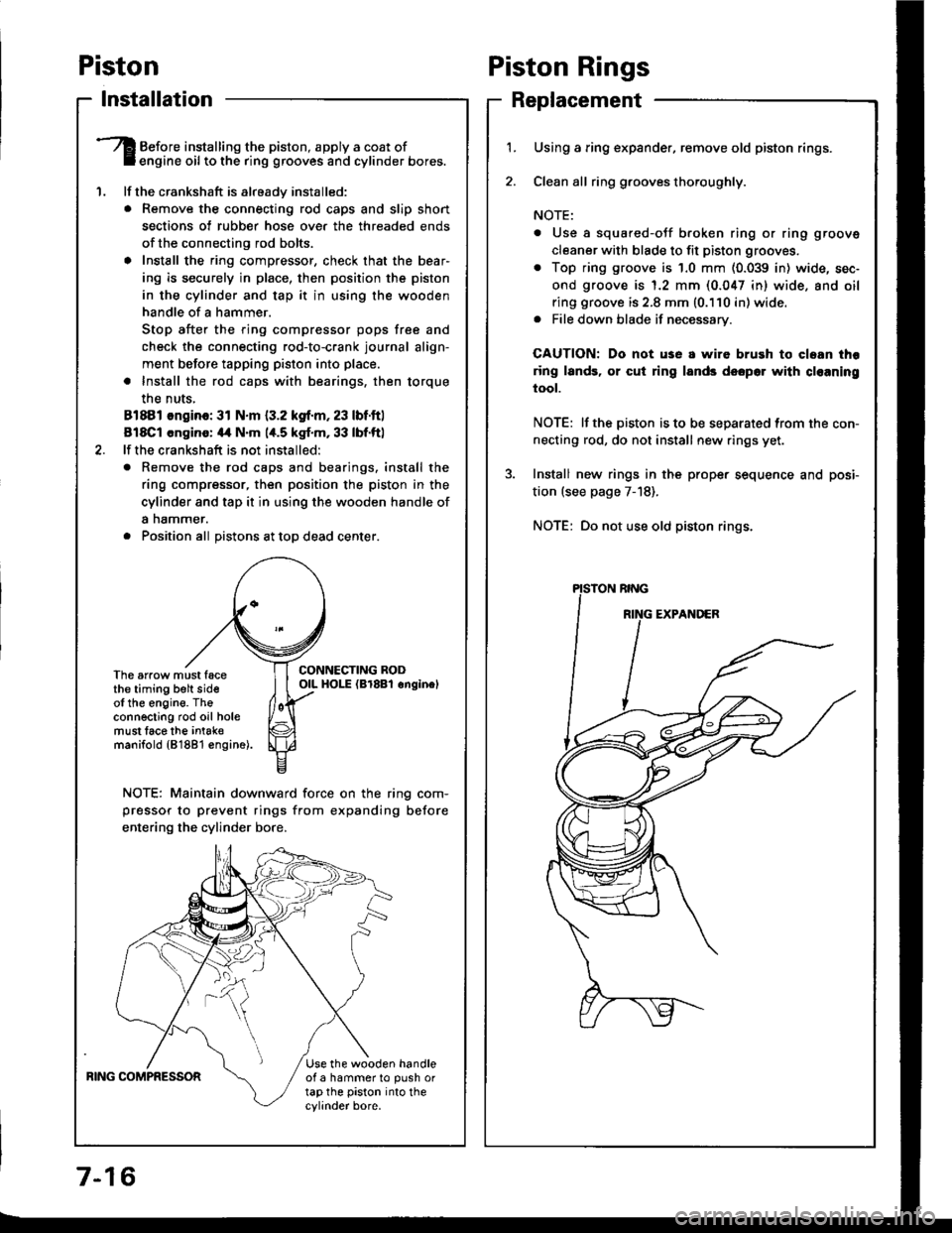
Before installing the piston, apply a coat ofengine oil to the ring grooves and cylinder bores.
lf the crankshaft is already installed:
. Remove the connecting rod caps and slip short
sections of rubber hose ove. the threaded ends
of the connecting rod bolts.
a Install the ring compressor, check that the bear'
ing is securely in place, then position the piston
in the cylinder and tap it in using the wooden
handle of a hammer.
Stop after the ring compressor pops free and
check the connecting rod-to-crank journal align-
ment before tapping piston into place.
. Install the rod caps with bearings, then torque
the nuts,
81881 ongino: 31 N.m {3.2 kgf.m, 23 lbf.ftl
818C1 cngino: 44 N'm 1,t.5 kgf.m, 33 lbf.ftl
lf the crankshaft is not installed:
o Remove the rod caps and bearings. install the
ring compressor, then position the piston in the
cylinder and tap it in using the wooden handle of
a nammer.
. Position all Distons at toD dead center.
CONNECTING RODOIL HOI-E (Br8Bl onginelThe arrow must facethe timing belt sideof the engine. Theconnecting rod oil holemust lace the intak€manifold {81881 €ngine).
NOTE: Maintain downward force on the ring com-
pressor to prevent rings from expanding before
entering the cylinder bore,
BING COMPRESSORUse the wooden handleof a hammer to push ortap the piston into thecylinder bore.
Piston Rings
Replacement
1.Using a ring expander, remove old piston rings.
Clean all ring g.ooves thoroughly.
NOTE:
. Use a squared-oJf broken ring or ring groove
cleaner with blade to fit piston grooves.
. Top ring groove is 1.0 mm (0.039 in) wide, sec-
ond groove is 1.2 mm (0.047 in) wide. and oil
ring groove is 2.8 mm (0.110 in) wide.. File down blade if necessary.
CAUTION: Do not use a wire brush to cloan thr
ring lands, or cut ring lands dsopo. with cl€aning
tool.
NOTE: lf the piston is to be separated from the con-
necting rod, do not install new rings yet.
Install new rings in the prope. sequence and posi-
tion (see page 7-18).
NOTE: Do not use old piston rings.
Page 165 of 1413

11.lnstallthe oil screen.
Installthe oil pan.
NOTE: Clean the oil pan gasket mating surfaces.
Tighten the bolts as shown below.
Torque: 12 N.m {1.2 kgf.m, 9 lbf'ft)
NOTE: Tighten the bolts and nuts in two steps and
toroue the bolts in a crisscross pattern
1'�I
Oil Seal
lnstallation
The seal surface on the block should be dry.
Apply a light cost of oil to the crankshaft and to
the liD of the seal.
Drive in flywheel end seal against right side cover.
NOTE: Drive the end seal in squarely.
DRIVER07t,49 - (xll(xtoo
2. Confirm that clearance is equal all the way around
with a fe€ler gauge.
Cler.6nce: 0.5 - 0.8 mm (0.02 - 0.03 inl
RIGHT SIDECOVER
NOTE: Reter to right column and 8-10 lor installa-
tion of the oil pump side oil seal.
lnstall sealwith thepart number sidetacing out.
7-25
Page 173 of 1413

Install the oil tilter by hand.
After the rubber sesl seats, tighten the oil filter clock-
wise with the special tool.
Tighten: 7/8 turn clockwise.
Tightening torque: 22 N.m (2.2 kgf'm, 16 lbf'ft)
CAUTION: Installation other than the abova ploce-
dure could r6suh in serious engine damag€ due to
oil leakage.
OIL FILTEB WRENCH07912-6110001
4.
_l-
8-7
Eight numbers {'l to 8) are printed on the surface of
rhe filter.
The following explains the procedure for tightening
filters using these numbers.
1 ) Make a mark on the cvlinder block under the num-
ber that shows al the bottom of the filter when
the rubber seal is seated.
2) Tighten the tilter by turning it clockwise seven
numbers from the marked point. For example, if
a mark is made under the number 2 when the tub-
ber seal is seated. the filter should be tightened
until the number 'l comes up to the marked point.
Number when rubberseal is seated.Number after tightening.
MARK
Number when rubber
seal is seated46I
Number after tightening8?o7
5. After installation, till the engine with oil up to the
specified level, run the engine for more than 3
minutes, then check for oil leakage and oil level.
.41
Page 174 of 1413

Oil Pressure
Testing
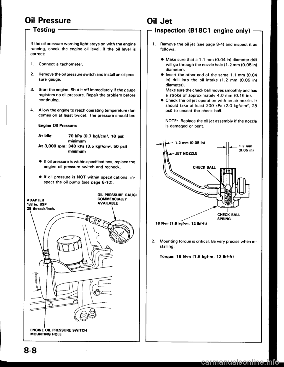
lf the oil pressure warning light stays on with the enginerunning, check the engine oil level. lf the oil level is
correct:
1. Connect a tachometer.
2. Remove the oil pressure switch and install an oil pres-
sure gauge.
3. Stan the engine. Shut it off immediately if the gauge
registers no oil pressure. Repair the problem before
continuing.
4. Allow the engine to reach operating temperatu,e {fancomes on at least twice). The Dressure should be:
Engine Oil Pressure:
At ldle: 70 kPa (0.7 kgf/cmr, 10 psi)
minimum
At 3,OOO lpm: 340 kPa {3.5 kgf/cmz, 50 psi}
minimum
a lJ oil pressure is within speciJications, replace the
engine oil pressure switch and recheck.
a lf oil pressure is NOT within specifications, in-
spect the oil pump (see page 8-1O).
1.2 mm 10.05 in)
'16 N.m (1.6 kgt.m, l2lbt.ftl
Oil Jet
Inspection (B18C1 engine only|
Remove the oil jet (see page 8-4) and inspect it as
follows.
a Make sure that a I .l mm (O.04 in) diameter drill
will go through the nozzle hole {1 .2 mm {O.OS in)
diameterl.
a Insert the other end of the same 1.1 mm (O.O4
in) drill into the oil intake {1.2 rnm {0.05 in}
diameter).
Make sure the check ball moves smoothlv and has
a stroke of approximately 4.0 mm {O. 16 in).a Check the oil jet operation with an air nozzle. lt
should take at least 2OO kPa (2.O kgf/cmr,28
Dsi) 10 unseat the check ball.
NOTE: Replace the oiljet assembly if the nozzle
is damaged or bent.
2. Mounting torque is critical. Be very precise when in-
stalling.
Torque: 16 N.m (1.6 kgt.m, 12lbf.ftl
OIL PRESSURE GAUGECOMMERCIALLYAVAILABI.E
8-8
Page 233 of 1413

3. Fuel Cut-oft Control
a During deceleration with the throttle valve closed, current to the {uel injectors is cut otJ to improve fuel economy
at speeds over tollowing rpm:
. 8188l engine: 91O tpm (Canada model: 1,O50 rpm)
. 818C1 engine: 95O tpm (Canada model: l,O5O rpm)
a Fuel cut-olf action also takes place when engine speed exceeds, 7,O0O rpm {81 8B1 engine), 8,1O0 rpm (B 18Cl
engine), regardless oI the position of the throttle valve, to protect the engine from ovet-revving.
A/C Compressor Clutch Relay
When the ECM receives a domand for cooling trom the air conditioning system, it del8ys the compressor from being
enetgized, and enriches the mixture to assure smooth transition to the A/C mode.
Evaporative Emission (EVAP) Purge Control Solenoid Valve
When the engine coolant tempersture is below 163oF {73"C), the ECM supplies a ground to the EVAP pu.ge control
solenoid valve which cuts vacuum to the EVAP purge control diaphragm valve.
Intake Air Bypsss (lAB) Control Sol€noid Valve
When the engine rpm is below 5,750 rpm, the IAB control solenoid valve is activated by a signal from the ECM,
intske air flows through the long intake path, then high torque is delivered. At spaeds highe. than 5,750 rpm, the
solenoid valve is deactivated by the ECM, and intake air flows through the short intake path in order to reduce the
resistance in airflow.
ECM fail-safe/bEck-up Functions
1. Fail-sate Function
When an abnormality occurs in a signal from a sensor, the ECM ignores that signal and assumes a pre-progtammed
value tor that sensor that allows the engine to continue to run.
Back-uD Function
When an abnormalitv occurs in the ECM itself, the fuel iniectors are controlled by a back-up citcuit independent of
the system in order to permit minimal driving.
Self-diagnosis Function IMaltunction Indicator Lamp {MlL)1
Wh6n an abnormality occurs in a signal from a sensor, the ECM supplies ground for the MIL and stores the code
in erasable memory. When the ignition is initially turned on, the ECM supplies ground tor the MIL tor two seconds
to check the MIL bulb condition.
Two Trio Detection Method
To prevent tals€ indications, th€ Two Trip Dstection Method is used for the HO2S and fuel metering-related self-
diagnostic tunctions. When an abnormslity occurs, the ECM stores it in its memo.y. Wh€n the ssme sbnormality
recurs alter the ignition switch is turned OFF and ON ag8in, the ECM informs the driver by lighting the MlL.
However, to ease troubleshooting, this function is canc€ll€d when you short the service check connector. The MIL
will then blink immedistelv when an abnormality occurs.
4.
6.
2
4.
11-41
Page 340 of 1413

Clutch Disc,
l.
t
Flywheel, Flywheel BearingPressure Plate
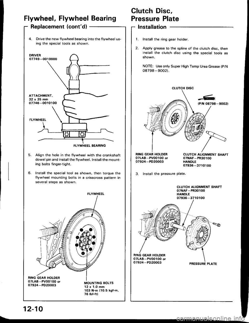
Replacement (cont'd)Installation
Install the ring gear holder.
Apply grease to the spline of the clutch disc, theninstall the clutch disc using the special tools assnown.
NOTE: Use only Super High Temp Urea Grease (P/N
08798-9OO2).
CLUTCH DISC
RING GEAR HOLDEROTLAB-PVOOI O0 ot07924-PD20003
3. Instali the pressure
CLUTCH ALIGNMENT SHAFT07NAF-PR30100HANDLE07936-3710100
plate.
CLUTCH ALIGNMENT SHAFToTNAF-PR30100HANDLE
PRESSURE PLATE
12-10
4. Drive the new flywheel bearing into the flywheel us-
ing rhe special tools as shown.
DRIVER07749-O010000
ATTACHMENT.32x35mm07746-OOlO100
o.
5.
FLYWHEEL
Align the hole in the flywheel with the crankshaft
dowel pin and installthe flywheel. Installthe mount-
ing bolts finger-tight.
Install the special tool as shown, then torque the
flywheel mounting bolts in a crisscross pattern in
several steDs as shown.
MOUNTING BOLTS12 x 1.0 mm103 N.m 110.5 kgf.m,76 tbf.fr)
FLYWHEEL BEARING
FLYWHEEL
07936-3710100
t\_
Page 341 of 1413

spection
release fork boot trom the clutch4. Torque the mounting bolts in a crisscross pattern as
shown. Tighten the bolts in several steps to prevent
warping the diaphragm spring.
8 x 1.25 mm25 N.m 12.6 kgt'm,19 tbt.ftl
2. Remove the release tork trom the clutch housing by
squeezing the release fork set spring with pliers. Re-
move the release bearing.
Check the release bearing for play by spinning it by
hand.
CAUTION: The release boaring i6 packed with
grease. Do not wash it in solvent.
Remove the special tools.
Recheck the diaphragm spring fingers tor height (see
page 12-7]..
Release Bearing
Removal/ln
1. Remove the
housing.
CLUTCH HOUSING
RELEASE FORK
-24/--2,t'.2424?'
IJ
l{ there is excessive plaY, rep)ace the rdease\Ear-
ing with a new one.
,F=:=