1993 VOLKSWAGEN CORRADO diagram
[x] Cancel search: diagramPage 2 of 920

HOW TO USE SYSTEM WIRING DIAGRAMSI - SYSTEM/COMPONENT TESTSINSTRUMENT PANELINTERFERENCE VERIFICATION CHECK FOR OHC ENGINEJ - PIN VOLTAGE CHARTSL - WIRING DIAGRAMSM - VACUUM DIAGRAMSMAINTENANCE INFORMATIONMAINTENANCE REMINDER LIGHT RESET PROCEDURESMETRIC CONVERSIONSMIRRORS - POWERN - REMOVE/INSTALL/OVERHAULP - EGR FUNCTION TESTINGPRE-ALIGNMENT CHECKSRIDING HEIGHT ADJUSTMENTSCHEDULED SERVICESSPECIFICATIONS & ELECTRIC COOLING FANSSTARTERSTEERING COLUMNSTEERING COLUMN SWITCHESSTEERING GEAR - POWER RACK & PINIONSUN ROOF - POWERSUSPENSION - FRONTSUSPENSION - REARSYSTEM WIRING DIAGRAMSTRANSMISSION REMOVAL & INSTALLATION - A/TTRANSMISSION REMOVAL & INSTALLATION - M/TTRANSMISSION SERVICING - A/TTRANSMISSION SERVICING - M/TTROUBLE SHOOTING - BASIC PROCEDURESVR65 ENGINE: AFFIX NEW VACUUM HOSE ROUTING LABELWAVEFORMS - INJECTOR PATTERN TUTORIALWHEEL ALIGNMENT SPECIFICATIONS & PROCEDURESWHEEL ALIGNMENT THEORY/OPERATIONWIPER/WASHER SYSTEMWIRING DIAGRAM SYMBOLSWIRING DIAGRAMSWIRING HARNESS CHAFING MAY CAUSE ENGINE STALL
Page 385 of 920

A/C-HEATER SYSTEM - MANUAL
Article Text (p. 10)
1993 Volkswagen Corrado
For Volkswagen Technical Site: http://vw.belcom.ru
Copyright © 1998 Mitchell Repair Information Company, LLC
Wednesday, March 22, 2000 08:49PM
INSTRUMENT PANEL
Removal & Installation
1) Disable air bag system. See AIR BAG SYSTEM SAFETY article
in GENERAL SERVICING. Disconnect battery. Remove storage trays and
panel under left side of instrument panel. Remove steering wheel.
Remove trim panel around instrument cluster.
2) Remove center console. Remove dash vents at each side,
glove box and radio. Remove center storage box, A/C-heater control
panel trim, and A/C-heater control panel screws. Push A/C-heater
control panel away from instrument panel.
3) Remove screws at both sides of instrument panel, at center
support, and 2 screws next to windshield. Detach instrument panel and
pull part way out.
4) Disconnect wiring harnesses from instrument panel.
Disconnect speedometer cable, if present. Remove instrument panel. To
install, reverse removal procedure.
THERMOSTAT
Removal & Installation
1) Remove thermostat cover. See Fig. 3. Remove thermostat
mounting screw and disconnect harness connector. Remove thermostat by
pulling sensing (capillary) tube through grommet.
2) To install, reverse removal procedures. Measure back 13"
(330 mm) from end of sensing tube and tape spot. Insert sensing tube
into evaporator guide channel up to tape.
TORQUE SPECIFICATIONS
TORQUE SPECIFICATIONS TABLEÄÄÄÄÄÄÄÄÄÄÄÄÄÄÄÄÄÄÄÄÄÄÄÄÄÄÄÄÄÄÄÄÄÄÄÄÄÄÄÄÄÄÄÄÄÄÄÄÄÄÄÄÄÄApplication Ft. Lbs. (N.m)
A/C Compressor Bolt/Nut .................... 33 (45)
A/C Compressor Bracket Bolt/Nut ............ 25 (35)
A/C Compressor Hoses
Discharge ................................. 18 (25)
Suction ................................... 25 (35)
ÄÄÄÄÄÄÄÄÄÄÄÄÄÄÄÄÄÄÄÄÄÄÄÄÄÄÄÄÄÄÄÄÄÄÄÄÄÄÄÄÄÄÄÄÄÄÄÄÄÄÄÄÄÄ WIRING DIAGRAMS
Page 386 of 920

A/C-HEATER SYSTEM - MANUAL
Article Text (p. 11)
1993 Volkswagen Corrado
For Volkswagen Technical Site: http://vw.belcom.ru
Copyright © 1998 Mitchell Repair Information Company, LLC
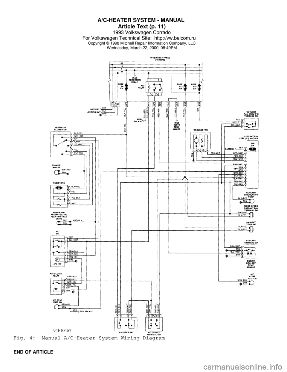
Wednesday, March 22, 2000 08:49PMFig. 4: Manual A/C-Heater System Wiring Diagram
END OF ARTICLE
Page 387 of 920

AA - USING THIS SECTION (GENERAL HELP INFORMATION)
Article Text
1993 Volkswagen Corrado
For Volkswagen Technical Site: http://vw.belcom.ru
Copyright © 1998 Mitchell Repair Information Company, LLC
Wednesday, March 22, 2000 08:49PM
ARTICLE BEGINNING
ENGINE PERFORMANCE
How To Use This Section
INTRODUCTION
NOTE: Because there are so many possible combinations of
articles for the different manufacturers and models,
the new hyper-text capabilities built into this product
DO NOT apply to this article.
It is the purpose of this repair information system to help
professional automotive technicians maintain top vehicle performance
and correct driveability problems related to today's high tech
vehicles.
Because of the limited amount of space allowable for the this
product, our titles have been condensed to fit into the menus. An
alphabetical designation has been added to the front of each title to
allow the titles to be displayed in a way that reflects their
respective order of use. References to the titles in some of the
diagnostic flow charts sometimes will not correlate with the titles in
the this product menu. If not, refer to the MENU CROSS-REFERENCE table
below.
MENU CROSS-REFERENCE TABLEÄÄÄÄÄÄÄÄÄÄÄÄÄÄÄÄÄÄÄÄÄÄÄÄÄÄÄÄÄÄÄÄÄÄÄÄÄÄÄÄÄÄÄÄÄÄÄÄÄÄÄÄÄÄÄÄÄÄÄÄÄÄÄÄÄÄÄÄÄÄTitle Associate Print (Book) Title:
A - ENGINE/VIN I D .................................... Introduction
B - EMISSION APPLICATION ..................... Emission Applications
C - TUNE-UP SPECS .............. Service & Adjustment Specifications
C - SPECIFICATIONS ............. Service & Adjustment Specifications
D - ADJUSTMENTS ............................. On-Vehicle Adjustments
E - THEORY/OPERATION ............................ Theory & Operation
F - BASIC TESTING ...................... Basic Diagnostic Procedures
G - TESTS W/ CODES ................................ Self-Diagnostics
H - TESTS W/O CODES .................... Trouble Shooting - No Codes
I - SYS/COMP TESTS ..................... Systems & Component Testing
J - PIN VOLTAGE CHARTS .......................... Pin Voltage Charts
K - SENSOR RANGE CHARTS .............. Sensor Operating Range Charts
L - WIRING DIAGRAMS ................................ Wiring Diagrams
M - VACUUM DIAGRAMS ................................ Vacuum Diagrams
N - REMOVE/INSTALL/OHAUL .......... Removal, Overhaul & Installation
ÄÄÄÄÄÄÄÄÄÄÄÄÄÄÄÄÄÄÄÄÄÄÄÄÄÄÄÄÄÄÄÄÄÄÄÄÄÄÄÄÄÄÄÄÄÄÄÄÄÄÄÄÄÄÄÄÄÄÄÄÄÄÄÄÄÄÄÄÄÄ Because of this we recommend that you read the rest of these
INTRODUCTION paragraphs to better understand why the information is
presented in this new format.
The A - ENGINE/VIN I D article will help you identify the
vehicle and its systems. It will also explain the VIN code and in many
cases, show its location.
Page 388 of 920

AA - USING THIS SECTION (GENERAL HELP INFORMATION)
Article Text (p. 2)
1993 Volkswagen Corrado
For Volkswagen Technical Site: http://vw.belcom.ru
Copyright © 1998 Mitchell Repair Information Company, LLC
Wednesday, March 22, 2000 08:49PM
If you want "TUNE-UP" type information, see D - ADJUSTMENTS
for the adjustment procedures. If you are familiar with the
procedures, but need a quick way to find the specification, go to C -
TUNE-UP SPECS or C - SPECIFICATIONS for the specifications pertaining
to the vehicle.
When diagnosing driveability problems, first go to F - BASIC
TESTING. This article is here to help eliminate wasted diagnostic
time. If the basic systems are working properly, go to G - TESTS W/
CODES.
If the vehicle still is having a driveability problem or if
the vehicle has no self-diagnostic system, go to H - TESTS W/O CODES.
This article will help you diagnose the problem by symptom, locate the
symptom exhibited by the vehicle, and inspect or test the items which
may be causing the problem.
After finding which specific system or component requires
testing, use the I - SYS/COMP TESTS article to tests the systems and
components. We have also included (when available) pin voltage charts
and sensor range charts. These can be found in J - PIN VOLTAGE CHARTS
and K - SENSOR RANGE CHARTS.
Also included in this section are wiring diagrams and vacuum
diagrams. These can be found in L - WIRING DIAGRAMS and M - VACUUM
DIAGRAMS.
When all diagnostic tests have been performed and the problem
has been discovered, it may be necessary to replace or overhaul the
defective part. This information can be found in
N - REMOVE/INSTALL/OHAUL.
The content of each of these articles is outlined below. As a
summary of the driveability diagnosis, see ROUTINE OUTLINE in this
article.
A - ENGINE/VIN ID
This article shows how to identify the model and engine by
its Vehicle Identification Number (VIN). A model coverage chart shows
each model and engine, the fuel system, ignition system and engine
code. The engine serial number locations are also included in this
article.
B - EMISSION APPLICATION
These charts identify the emission systems and sub-systems
applicable to each model and engine combination.
C - TUNE-UP SPECS
This is a collection of quick-reference type specifications.
This article is helpful when you are familiar with proper adjustment
procedures and only need specifications. Included in this section are:
* Battery specifications.
* Fluid capacities.
Page 391 of 920

AA - USING THIS SECTION (GENERAL HELP INFORMATION)
Article Text (p. 5)
1993 Volkswagen Corrado
For Volkswagen Technical Site: http://vw.belcom.ru
Copyright © 1998 Mitchell Repair Information Company, LLC
Wednesday, March 22, 2000 08:49PM
sensor is out of calibration. A sensor that is out of calibration may
not set a trouble code, but it will cause driveability problems.
L - WIRING DIAGRAMS
Use these WIRING DIAGRAMS to identify and trace component
circuits, locate shorts and opens in circuits, and understand how
individual circuits function as part of a system. The diagrams in this
article are only for fuel, ignition and emission systems
M - VACUUM DIAGRAMS
The VACUUM DIAGRAMS will assist you in finding incorrectly
routed vacuum hoses which may cause driveability problems or computer
indicated malfunctions.
N - REMOVE/INSTALL/OHAUL
N - REMOVE/INSTALL/OHAUL contains information found in the
sub-headings of REMOVAL, OVERHAUL & INSTALLATION. These are procedures
and specifications required to remove, overhaul (if possible) and
install components related to engine performance.
WHERE TO START
PERFORM BASIC INSPECTION
1) Verify customer complaint.
2) Perform visual inspection. See F - BASIC TESTING.
3) Test engine sub-system to determine that the following
systems are functioning properly. See F- BASIC TESTING.
* Mechanical conditions (compression)
* Ignition output
* Fuel Delivery
4) Check air induction system for leaks.
5) Check & adjust basic engine settings listed below to
ensure they are to specification. See D - ADJUSTMENTS.
* Ignition timing
* Idle speed
CHECK FOR TROUBLE CODES
1) If equipped with self-diagnostics, check for trouble
codes. Refer to G - TESTS W/ CODES.
2) Repair causes of trouble code(s).
3) Clear control unit memory.
SYMPTOM DIAGNOSIS
Page 421 of 920

ANTI-LOCK BRAKE SYSTEM
Article Text (p. 11)
1993 Volkswagen Corrado
For Volkswagen Technical Site: http://vw.belcom.ru
Copyright © 1998 Mitchell Repair Information Company, LLC
Wednesday, March 22, 2000 08:57PM
Connect a jumper wire ECU between ECU connector terminals No.
2, 16 and 35. See Fig. 2. Depress brake pedal. Left front wheel should
be locked up. Turn ignition on. Left front wheel should rotate. If
wheel does not rotate, replace hydraulic modulator. Turn ignition off.
REMOVAL & INSTALLATION
HYDRAULIC MODULATOR/PUMP
Removal & Installation
1) Depressurize brake system. See DEPRESSURIZING BRAKE
SYSTEM. Disconnect negative battery cable. Unplug all electrical
connectors from hydraulic modulator/pump. Identify and disconnect all
hydraulic lines from hydraulic modulator/pump. Plug all line openings.
2) From inside passenger compartment, remove push rod clevis
pin. Remove hydraulic modulator/pump retaining nuts. Remove hydraulic
modulator/pump. To install, reverse removal procedure. Tighten all
fittings to specification. See TORQUE SPECIFICATIONS table. Bleed
brake system. See BLEEDING BRAKE SYSTEM.
WHEEL SPEED SENSORS
NOTE: To protect magnetic part of sensor, always leave new wheel
speed sensor in special packaging until ready for
installation.
Removal & Installation
Remove bolt retaining wheel speed sensor. Unplug connector.
Remove wheel speed sensor. To install, apply Lubricant (G-000-650) to
sensor. Install sensor, and tighten retaining bolt to 84 INCH lbs. (10
N.m).
TORQUE SPECIFICATIONS
TORQUE SPECIFICATIONS TABLEÄÄÄÄÄÄÄÄÄÄÄÄÄÄÄÄÄÄÄÄÄÄÄÄÄÄÄÄÄÄÄÄÄÄÄÄÄÄÄÄÄÄÄÄÄÄÄÄÄÄÄÄÄÄÄÄÄÄÄÄÄÄÄÄÄÄÄÄÄÄApplications Ft. Lbs. (N.m)
Brake Lines-To-Hydraulic Modulator/Pump .................... 11 (15)
Hydraulic Modulator/Pump Retaining Nuts .................... 18 (25)
INCH Lbs. (N.m)
Wheel Sensor Retaining Bolt ................................ 89 (10)
ÄÄÄÄÄÄÄÄÄÄÄÄÄÄÄÄÄÄÄÄÄÄÄÄÄÄÄÄÄÄÄÄÄÄÄÄÄÄÄÄÄÄÄÄÄÄÄÄÄÄÄÄÄÄÄÄÄÄÄÄÄÄÄÄÄÄÄÄÄÄ WIRING DIAGRAMS
Page 422 of 920

ANTI-LOCK BRAKE SYSTEM
Article Text (p. 12)
1993 Volkswagen Corrado
For Volkswagen Technical Site: http://vw.belcom.ru
Copyright © 1998 Mitchell Repair Information Company, LLC
Wednesday, March 22, 2000 08:57PMFig. 4: ABS Wiring Diagram (Corrado SLC)
END OF ARTICLE