1993 VOLKSWAGEN CORRADO light
[x] Cancel search: lightPage 512 of 920

E - THEORY/OPERATION
Article Text (p. 7)
1993 Volkswagen Corrado
For Volkswagen Technical Site: http://vw.belcom.ru
Copyright © 1998 Mitchell Repair Information Company, LLC
Wednesday, March 22, 2000 09:09PM
speed, the vapors will be drawn into intake manifold. Depending on
engine load and oxygen sensor signal, the fuel evaporative (frequency)
valve will regulate the amount of vapors entering the intake manifold.
SELF-DIAGNOSTIC SYSTEM
The Electronic Control Module (ECM) recognizes faults (open
circuits, short circuits, missing signals, or a continuously applied
signal voltage) in the following circuits/components.
* EGR Frequency Valve
* EGR Temperature Sensor
* Engine Coolant Temperature Sensor
* Engine Speed (RPM)/Reference Sensor
* Fuel Evaporative (Frequency) Valve
* Hall Effect Sensor
* Idle Air Control/Stabilizer Valve
* Intake Air Temperature Sensor
* Knock Sensor(s)
* Throttle Valve Potentiometer
* Oxygen Sensor
MALFUNCTION INDICATOR (CHECK ENGINE) LIGHT
All California models are equipped with a malfunction
indicator (CHECK ENGINE) light. If CHECK ENGINE light comes on and
remains on during vehicle operation, cause of malfunction must be
determined. See the G - TESTS W/CODES article.
END OF ARTICLE
Page 528 of 920
EMISSION CONTROL VISUAL INSPECTION PROCEDURES
Article Text (p. 14)
1993 Volkswagen Corrado
For Volkswagen Technical Site: http://vw.belcom.ru
Copyright © 1998 Mitchell Repair Information Company, LLC
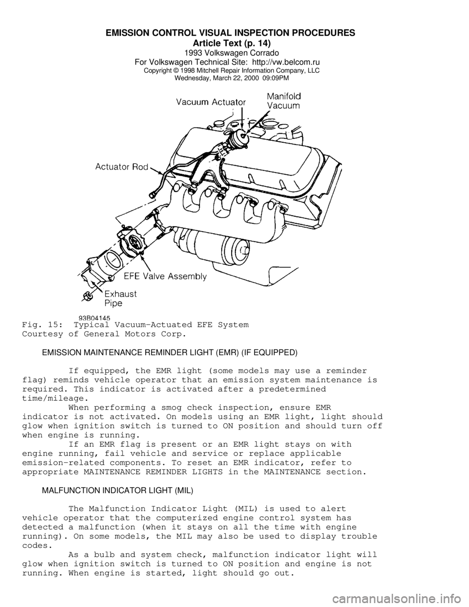
Wednesday, March 22, 2000 09:09PMFig. 15: Typical Vacuum-Actuated EFE System
Courtesy of General Motors Corp.
EMISSION MAINTENANCE REMINDER LIGHT (EMR) (IF EQUIPPED)
If equipped, the EMR light (some models may use a reminder
flag) reminds vehicle operator that an emission system maintenance is
required. This indicator is activated after a predetermined
time/mileage.
When performing a smog check inspection, ensure EMR
indicator is not activated. On models using an EMR light, light should
glow when ignition switch is turned to ON position and should turn off
when engine is running.
If an EMR flag is present or an EMR light stays on with
engine running, fail vehicle and service or replace applicable
emission-related components. To reset an EMR indicator, refer to
appropriate MAINTENANCE REMINDER LIGHTS in the MAINTENANCE section.
MALFUNCTION INDICATOR LIGHT (MIL)
The Malfunction Indicator Light (MIL) is used to alert
vehicle operator that the computerized engine control system has
detected a malfunction (when it stays on all the time with engine
running). On some models, the MIL may also be used to display trouble
codes.
As a bulb and system check, malfunction indicator light will
glow when ignition switch is turned to ON position and engine is not
running. When engine is started, light should go out.
Page 531 of 920

ENGINE OVERHAUL PROCEDURES - GENERAL INFORMATION
Article Text (p. 2)
1993 Volkswagen Corrado
For Volkswagen Technical Site: http://vw.belcom.ru
Copyright © 1998 Mitchell Repair Information Company, LLC
Wednesday, March 22, 2000 09:09PM
Cracks which are outlined by the particles cause an
interruption in the magnetic field. The dry powder method of Magnaflux
can be used in normal light. A crack will appear as an obvious bright
line.
Fluorescent liquid is used in conjunction with a blacklight
in a second Magnaflux system called Magnaglo. This type of inspection
demands a darkened room. The crack will appear as a glowing line in
this process. Both systems require complete demagnetizing upon
completion of the inspection. Magnetic particle inspection applies to
ferrous materials only.
PENETRANT INSPECTION
Zyglo
The Zyglo process coats the material with a fluorescent dye
penetrant. The part is often warmed to expand cracks that will be
penetrated by the dye. When the coated part is subjected to inspection
with a blacklight, a crack will glow brightly. Developing solution
is often used to enhance results. Parts made of any material, such as
aluminum cylinder heads or plastics, may be tested using this process.
Dye Check
Penetrating dye is sprayed on the previously cleaned
component. Dye is left on component for 5-45 minutes, depending upon
material density. Component is then wiped clean and sprayed with a
developing solution. Surface cracks will show up as a bright line.
ULTRASONIC INSPECTION
If an expensive part is suspected of internal cracking,
Ultrasonic testing is used. Sound waves are used for component
inspection.
X-RAY INSPECTION
This form of inspection is used on highly stressed
components. X-ray inspection maybe used to detect internal and
external flaws in any material.
PRESSURE TESTING
Cylinder heads can be tested for cracks using a pressure
tester. Pressure testing is performed by plugging all but one of the
holes in the head and injecting air or water into the open passage.
Leaks are indicated by the appearance of wet or damp areas when using
water. When air is used, it is necessary to spray the head surface
with a soap solution. Bubbles will indicate a leak. Cylinder head may
also be submerged in water heated to specified temperature to check
for cracks created during heat expansion.
CLEANING PROCEDURES
Page 534 of 920
ENGINE OVERHAUL PROCEDURES - GENERAL INFORMATION
Article Text (p. 5)
1993 Volkswagen Corrado
For Volkswagen Technical Site: http://vw.belcom.ru
Copyright © 1998 Mitchell Repair Information Company, LLC
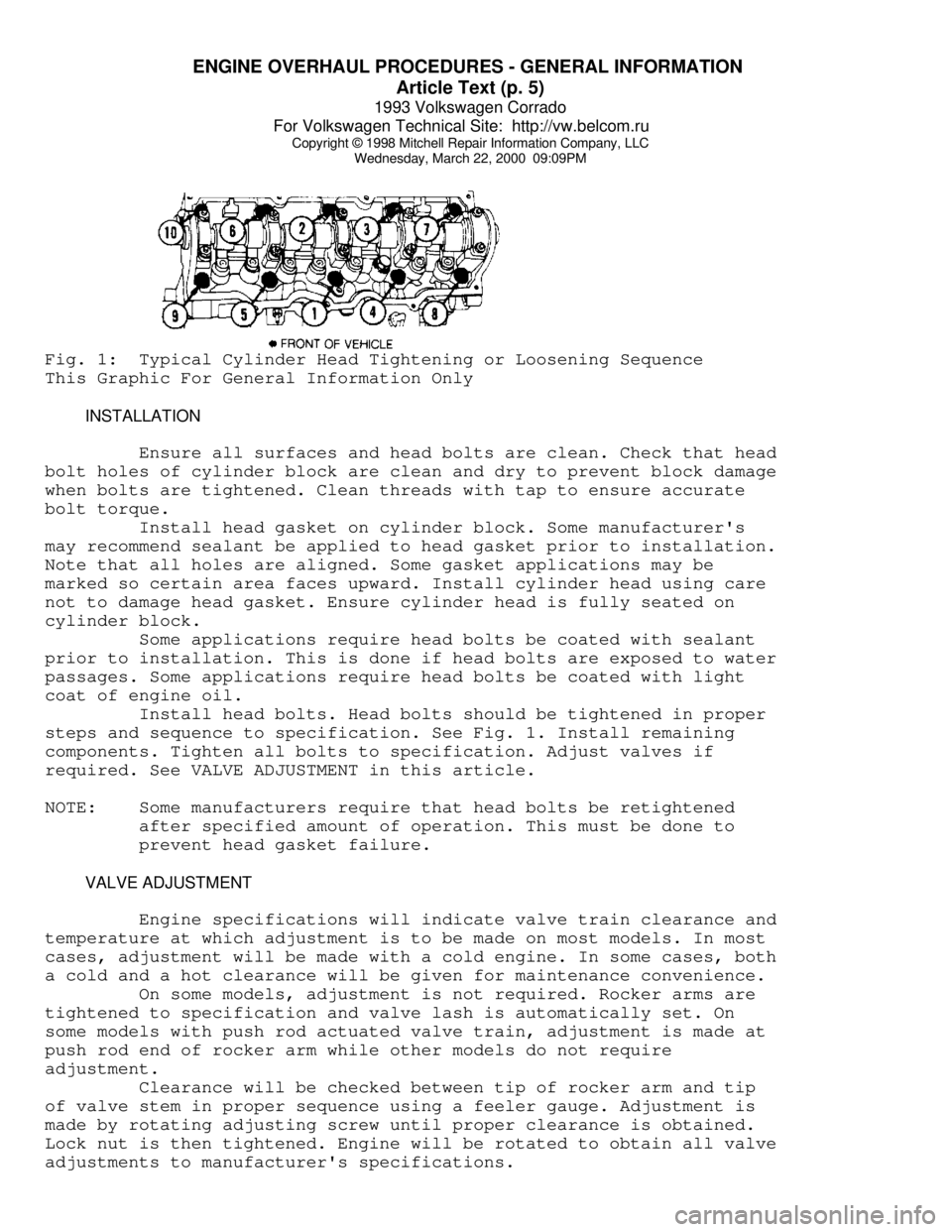
Wednesday, March 22, 2000 09:09PMFig. 1: Typical Cylinder Head Tightening or Loosening Sequence
This Graphic For General Information Only
INSTALLATION
Ensure all surfaces and head bolts are clean. Check that head
bolt holes of cylinder block are clean and dry to prevent block damage
when bolts are tightened. Clean threads with tap to ensure accurate
bolt torque.
Install head gasket on cylinder block. Some manufacturer's
may recommend sealant be applied to head gasket prior to installation.
Note that all holes are aligned. Some gasket applications may be
marked so certain area faces upward. Install cylinder head using care
not to damage head gasket. Ensure cylinder head is fully seated on
cylinder block.
Some applications require head bolts be coated with sealant
prior to installation. This is done if head bolts are exposed to water
passages. Some applications require head bolts be coated with light
coat of engine oil.
Install head bolts. Head bolts should be tightened in proper
steps and sequence to specification. See Fig. 1. Install remaining
components. Tighten all bolts to specification. Adjust valves if
required. See VALVE ADJUSTMENT in this article.
NOTE: Some manufacturers require that head bolts be retightened
after specified amount of operation. This must be done to
prevent head gasket failure.
VALVE ADJUSTMENT
Engine specifications will indicate valve train clearance and
temperature at which adjustment is to be made on most models. In most
cases, adjustment will be made with a cold engine. In some cases, both
a cold and a hot clearance will be given for maintenance convenience.
On some models, adjustment is not required. Rocker arms are
tightened to specification and valve lash is automatically set. On
some models with push rod actuated valve train, adjustment is made at
push rod end of rocker arm while other models do not require
adjustment.
Clearance will be checked between tip of rocker arm and tip
of valve stem in proper sequence using a feeler gauge. Adjustment is
made by rotating adjusting screw until proper clearance is obtained.
Lock nut is then tightened. Engine will be rotated to obtain all valve
adjustments to manufacturer's specifications.
Page 540 of 920
ENGINE OVERHAUL PROCEDURES - GENERAL INFORMATION
Article Text (p. 11)
1993 Volkswagen Corrado
For Volkswagen Technical Site: http://vw.belcom.ru
Copyright © 1998 Mitchell Repair Information Company, LLC
Wednesday, March 22, 2000 09:09PM
grinding machine.
Valve Lapping
During valve lapping of recent designed valves, be sure to
follow manufacturers recommendations. Surface hardening and materials
used with some valves do not permit lapping. Lapping process will
remove excessive amounts of the hardened surface.
Valve lapping is done to ensure adequate sealing between
valve face and seat. Use either a hand drill or lapping stick with
suction cup attached.
Moisten and attach suction cup to valve. Lubricate valve stem
and guide. Apply a thin coat of fine valve grinding compound between
valve and seat. Rotate lapping tool between the palms or with hand
drill.
Lift valve upward off the seat and change position often.
This is done to prevent grooving of valve seat. Lap valve until a
smooth polished seat is obtained. Thoroughly clean grinding compound
from components. Valve to valve seat concentricity should be checked.
See VALVE SEAT CONCENTRICITY.
CAUTION: Valve guides must be in good condition and free of carbon
deposits prior to valve seat grinding. Some engines contain
an induction hardened valve seat. Excessive material removal
will damage valve seats.
Valve Seat Grinding
Select coarse stone of correct size and angle for seat to be
ground. Ensure stone is true and has a smooth surface. Select correct
size pilot for valve guide dimension. Install pilot in valve guide.
Lightly lubricate pilot shaft. Install stone on pilot. Move stone off
and on the seat approximately 2 times per second during grinding
operation.
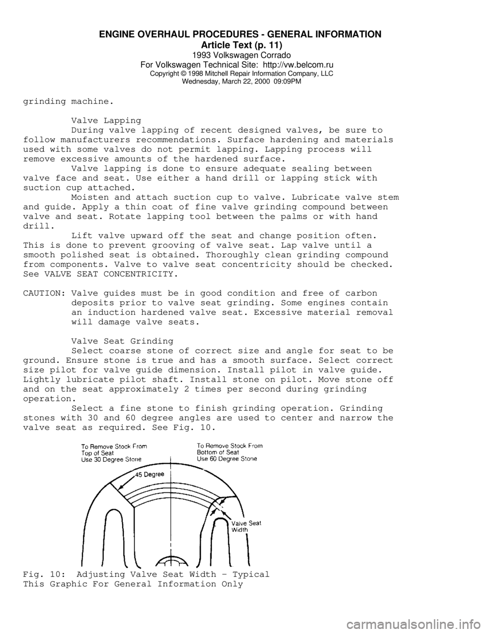
Select a fine stone to finish grinding operation. Grinding
stones with 30 and 60 degree angles are used to center and narrow the
valve seat as required. See Fig. 10.Fig. 10: Adjusting Valve Seat Width - Typical
This Graphic For General Information Only
Page 541 of 920
ENGINE OVERHAUL PROCEDURES - GENERAL INFORMATION
Article Text (p. 12)
1993 Volkswagen Corrado
For Volkswagen Technical Site: http://vw.belcom.ru
Copyright © 1998 Mitchell Repair Information Company, LLC
Wednesday, March 22, 2000 09:09PM
Valve Seat Replacement
Replacement of valve seat inserts is done by cutting out
the old insert and machining an oversize insert bore. Replacement
oversize insert is usually chilled and the cylinder head is sometimes
warmed. Valve seat is pressed into the head. This operation requires
specialized machine shop equipment.
Valve Seat Concentricity
Using dial gauge, install gauge pilot in valve guide.
Position gauge arm on the valve seat. Adjust dial indicator to zero.
Rotate arm 360 degrees and note reading. Runout should not exceed
specification.
To check valve-to-valve seat concentricity, coat valve face
lightly with Prussian Blue dye. Install valve and rotate it on valve
seat. If pattern is even and entire seat is coated at valve contact
point, valve is concentric with the seat.
REASSEMBLY
Valve Stem Installed Height
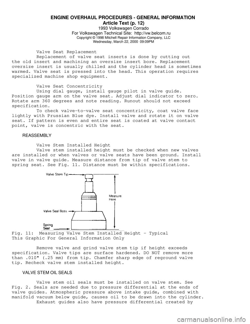
Valve stem installed height must be checked when new valves
are installed or when valves or valve seats have been ground. Install
valve in valve guide. Measure distance from tip of valve stem to
spring seat. See Fig. 11. Distance must be within specifications.Fig. 11: Measuring Valve Stem Installed Height - Typical
This Graphic For General Information Only
Remove valve and grind valve stem tip if height exceeds
specification. Valve tips are surface hardened. DO NOT remove more
than .010" (.25 mm) from tip. Chamfer sharp edge of reground valve
tip. Recheck valve stem installed height.
VALVE STEM OIL SEALS
Valve stem oil seals must be installed on valve stem. See
Fig. 2. Seals are needed due to pressure differential at the ends of
valve guides. Atmospheric pressure above intake guide, combined with
manifold vacuum below guide, causes oil to be drawn into the cylinder.
Exhaust guides also have pressure differential created by
Page 550 of 920
ENGINE OVERHAUL PROCEDURES - GENERAL INFORMATION
Article Text (p. 21)
1993 Volkswagen Corrado
For Volkswagen Technical Site: http://vw.belcom.ru
Copyright © 1998 Mitchell Repair Information Company, LLC
Wednesday, March 22, 2000 09:10PM
seated on crankshaft journal. Remove protectors. Install rod cap and
bearing. Lightly tighten connecting rod bolts. Repeat procedure for
remaining cylinders. Check bearing clearance. See
MAIN & CONNECTING ROD BEARING CLEARANCE in this article.
Once clearance is checked, lubricate journals and bearings.
Install bearing caps. Ensure marks are aligned on connecting rod and
cap. Tighten rod nuts or bolts to specification. Ensure rod moves
freely on crankshaft. Check connecting rod side clearance. See
CONNECTING ROD SIDE CLEARANCE in this article.
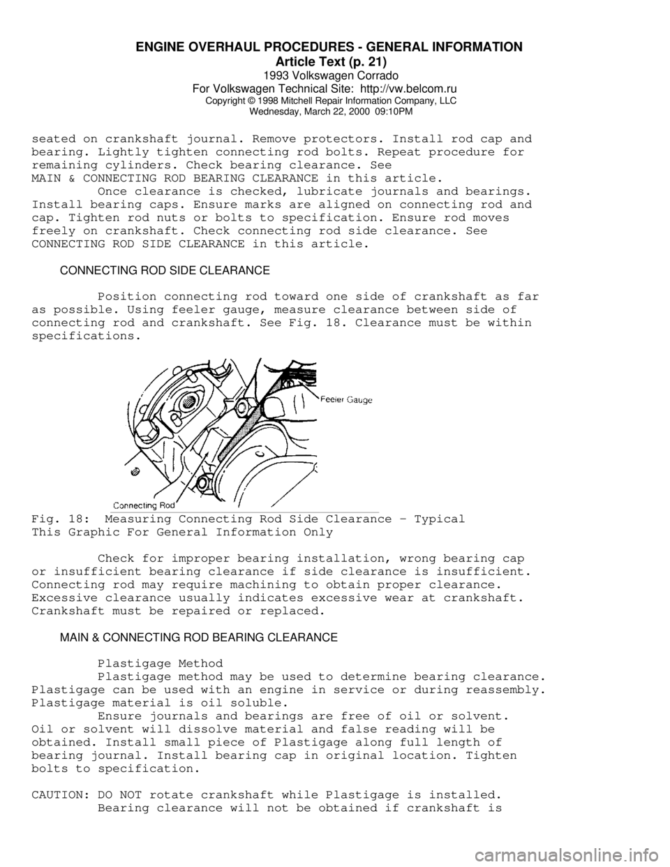
CONNECTING ROD SIDE CLEARANCE
Position connecting rod toward one side of crankshaft as far
as possible. Using feeler gauge, measure clearance between side of
connecting rod and crankshaft. See Fig. 18. Clearance must be within
specifications.Fig. 18: Measuring Connecting Rod Side Clearance - Typical
This Graphic For General Information Only
Check for improper bearing installation, wrong bearing cap
or insufficient bearing clearance if side clearance is insufficient.
Connecting rod may require machining to obtain proper clearance.
Excessive clearance usually indicates excessive wear at crankshaft.
Crankshaft must be repaired or replaced.
MAIN & CONNECTING ROD BEARING CLEARANCE
Plastigage Method
Plastigage method may be used to determine bearing clearance.
Plastigage can be used with an engine in service or during reassembly.
Plastigage material is oil soluble.
Ensure journals and bearings are free of oil or solvent.
Oil or solvent will dissolve material and false reading will be
obtained. Install small piece of Plastigage along full length of
bearing journal. Install bearing cap in original location. Tighten
bolts to specification.
CAUTION: DO NOT rotate crankshaft while Plastigage is installed.
Bearing clearance will not be obtained if crankshaft is
Page 556 of 920

ENGINE OVERHAUL PROCEDURES - GENERAL INFORMATION
Article Text (p. 27)
1993 Volkswagen Corrado
For Volkswagen Technical Site: http://vw.belcom.ru
Copyright © 1998 Mitchell Repair Information Company, LLC
Wednesday, March 22, 2000 09:10PM
the same time.
MAIN BEARING BORE & ALIGNMENT
For checking main bearing bore, remove all bearings from
cylinder block and main bearing caps. Install main bearing caps in
original location. Tighten bolts to specification. Using inside
micrometer, measure main bearing bore in 2 areas 90 degrees apart.
Determine bore size and out-of-round. If diameter is not within
specification, block must be align-bored.
For checking alignment, place a straightedge along centerline
of main bearing saddles. Check for clearance between straightedge and
main bearing saddles. Block must be align-bored if clearance is
present.
EXPANSION PLUG REMOVAL & INSTALLATION
Removal
Drill a hole in the center of expansion plug. Remove with
screwdriver or punch. Use care not to damage sealing surface.
Installation
Ensure sealing surface is free of burrs. Coat expansion plug
with sealer. Use a wooden dowel or pipe of slightly smaller diameter,
install expansion plug. Ensure expansion plug is evenly located.
OIL GALLERY PLUG REMOVAL & INSTALLATION
Removal
Remove threaded oil gallery plugs using the appropriate
wrench. Soft, press-in plugs are removed by drilling into plug and
installing a sheet metal screw. Remove plug with slide hammer or
pliers.
Installation
Ensure threads or sealing surface is clean. Coat threaded oil
gallery plugs with sealer and install. Replacement soft press-in plugs
are driven in place with a hammer and drift.
CAMSHAFT
* PLEASE READ THIS FIRST *
NOTE: Always refer to appropriate engine overhaul article in the
ENGINES section for complete overhaul procedures and
specifications for the vehicle being repaired.
CLEANING & INSPECTION
Clean camshaft with solvent. Ensure all oil passages are
clear. Inspect cam lobes and bearing journals for pitting, flaking or
scoring. Using micrometer, measure bearing journal O.D.