1993 VOLKSWAGEN CORRADO light
[x] Cancel search: lightPage 448 of 920
CLUTCH
Article Text (p. 3)
1993 Volkswagen Corrado
For Volkswagen Technical Site: http://vw.belcom.ru
Copyright © 1998 Mitchell Repair Information Company, LLC
Wednesday, March 22, 2000 08:58PM
front transmission mount. Attach Engine Support (10-222A) with Bases
(10-222A/1) to engine. Slightly tighten engine support and remove
starter. Remove left transaxle mount bracket.
5) Remove long left side transmission support bracket. Remove
balance weight from mount. Remove heat shield for right side inner CV
(constant velocity) joint.
6) Disconnect axle shafts at flanges and wire aside. Remove
left side transaxle mount from transaxle. It will be necessary to push
rearward on mount for clearance to remove long transaxle mount bolt.
7) Push transaxle mount to right and pull down to remove from
vehicle. Remove small gear carrier housing cover. Support transaxle
with floor jack. Remove rear transaxle mount. Remove lower transaxle-
to-engine bolts. Carefully pry transaxle from engine and lower.
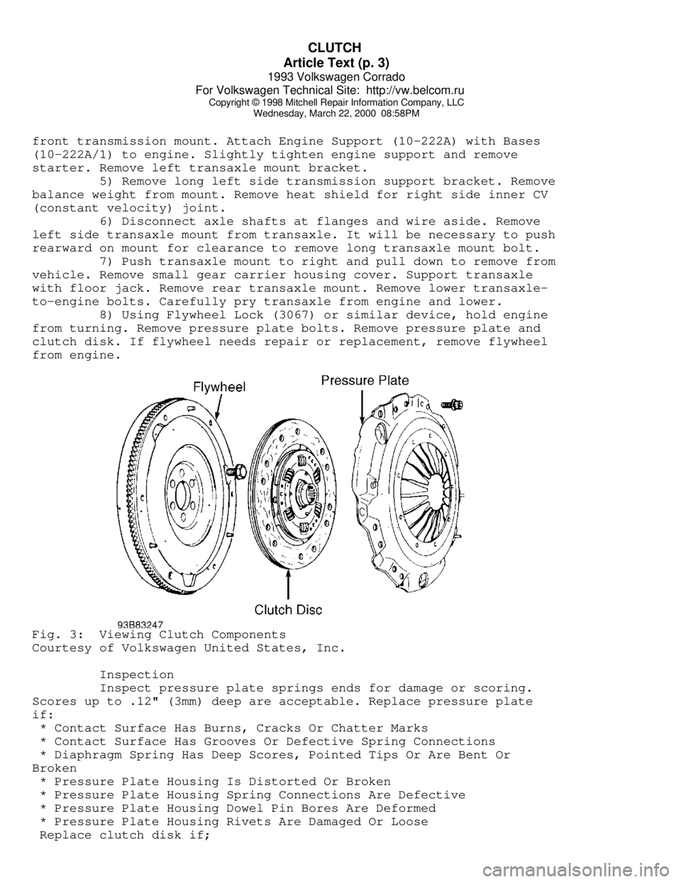
8) Using Flywheel Lock (3067) or similar device, hold engine
from turning. Remove pressure plate bolts. Remove pressure plate and
clutch disk. If flywheel needs repair or replacement, remove flywheel
from engine.Fig. 3: Viewing Clutch Components
Courtesy of Volkswagen United States, Inc.
Inspection
Inspect pressure plate springs ends for damage or scoring.
Scores up to .12" (3mm) deep are acceptable. Replace pressure plate
if:
* Contact Surface Has Burns, Cracks Or Chatter Marks
* Contact Surface Has Grooves Or Defective Spring Connections
* Diaphragm Spring Has Deep Scores, Pointed Tips Or Are Bent Or
Broken
* Pressure Plate Housing Is Distorted Or Broken
* Pressure Plate Housing Spring Connections Are Defective
* Pressure Plate Housing Dowel Pin Bores Are Deformed
* Pressure Plate Housing Rivets Are Damaged Or Loose
Replace clutch disk if;
Page 449 of 920
CLUTCH
Article Text (p. 4)
1993 Volkswagen Corrado
For Volkswagen Technical Site: http://vw.belcom.ru
Copyright © 1998 Mitchell Repair Information Company, LLC
Wednesday, March 22, 2000 08:58PM
* Worn To Surface Of Rivet Heads
* Rivets Are Loose, Missing Or Damaged
* Friction Material Is Oil Or Grease Soaked
* Friction Material Is Loose, Cracked Or Grooved
* Hub Is Rusted Or Damaged
* Springs Are Rusted Solid, Broken, Cracked Or Loose
* Torsion Damper Spring Guide Is Broken
* Torsion Damper Cover Damaged
* Torsion Damper Grooved Or Not Functioning
NOTE: Pressure plate has a protective grease coating. Remove
contact surface grease only. Service life will be shortened
if remaining portions of pressure plate protective grease
are removed.
Installation
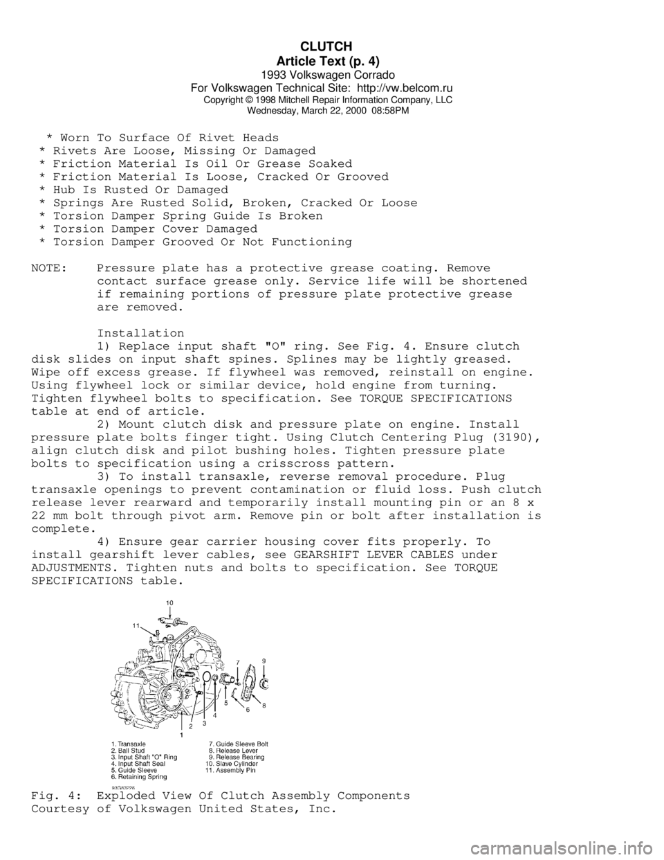
1) Replace input shaft "O" ring. See Fig. 4. Ensure clutch
disk slides on input shaft spines. Splines may be lightly greased.
Wipe off excess grease. If flywheel was removed, reinstall on engine.
Using flywheel lock or similar device, hold engine from turning.
Tighten flywheel bolts to specification. See TORQUE SPECIFICATIONS
table at end of article.
2) Mount clutch disk and pressure plate on engine. Install
pressure plate bolts finger tight. Using Clutch Centering Plug (3190),
align clutch disk and pilot bushing holes. Tighten pressure plate
bolts to specification using a crisscross pattern.
3) To install transaxle, reverse removal procedure. Plug
transaxle openings to prevent contamination or fluid loss. Push clutch
release lever rearward and temporarily install mounting pin or an 8 x
22 mm bolt through pivot arm. Remove pin or bolt after installation is
complete.
4) Ensure gear carrier housing cover fits properly. To
install gearshift lever cables, see GEARSHIFT LEVER CABLES under
ADJUSTMENTS. Tighten nuts and bolts to specification. See TORQUE
SPECIFICATIONS table.Fig. 4: Exploded View Of Clutch Assembly Components
Courtesy of Volkswagen United States, Inc.
Page 452 of 920

COMPUTER RELEARN PROCEDURES
Article Text (p. 2)
1993 Volkswagen Corrado
For Volkswagen Technical Site: http://vw.belcom.ru
Copyright © 1998 Mitchell Repair Information Company, LLC
Wednesday, March 22, 2000 08:58PM
"D" and allow engine to idle for one minute.
* Accelerate at normal throttle position (20-50%) until vehicle
shifts into top gear.
* Cruise at light to medium throttle.
* Decelerate to a stop, allowing vehicle to downshift, and use
brakes normally.
* Process may be repeated as necessary.
Manual Transmission
* Place transmission in Neutral position.
* Ensure emergency brake has been set and all accessories
are turned off.
* Start engine and bring to normal operating temperature.
* Allow vehicle to idle in Neutral for one minute.
* Initial relearn is complete: process will be completed during
normal driving.
Some manufacturers identify a specific relearn procedure
which will help establish suitable driveability during relearn stage.
These procedures are especially important if vehicle is equipped with
and electronically controlled automatic transmission or transaxle.
Always complete procedure before returning vehicle to customer.
END OF ARTICLE
Page 466 of 920
ELECTRICAL COMPONENT LOCATOR
Article Text (p. 8)
1993 Volkswagen Corrado
For Volkswagen Technical Site: http://vw.belcom.ru
Copyright © 1998 Mitchell Repair Information Company, LLC
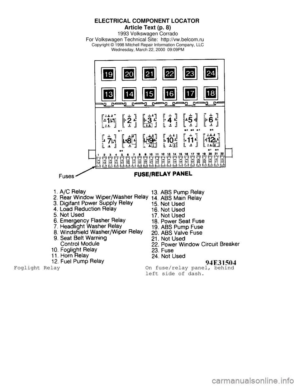
Wednesday, March 22, 2000 09:09PMFoglight Relay On fuse/relay panel, behind
left side of dash.
Page 468 of 920
ELECTRICAL COMPONENT LOCATOR
Article Text (p. 10)
1993 Volkswagen Corrado
For Volkswagen Technical Site: http://vw.belcom.ru
Copyright © 1998 Mitchell Repair Information Company, LLC
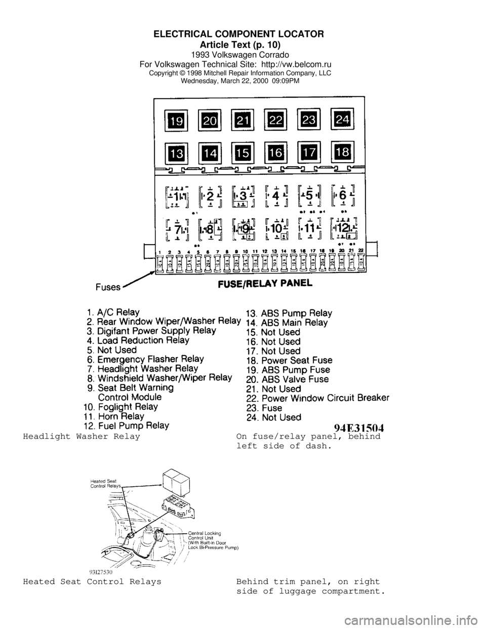
Wednesday, March 22, 2000 09:09PMHeadlight Washer Relay On fuse/relay panel, behind
left side of dash.Heated Seat Control Relays Behind trim panel, on right
side of luggage compartment.
Page 492 of 920
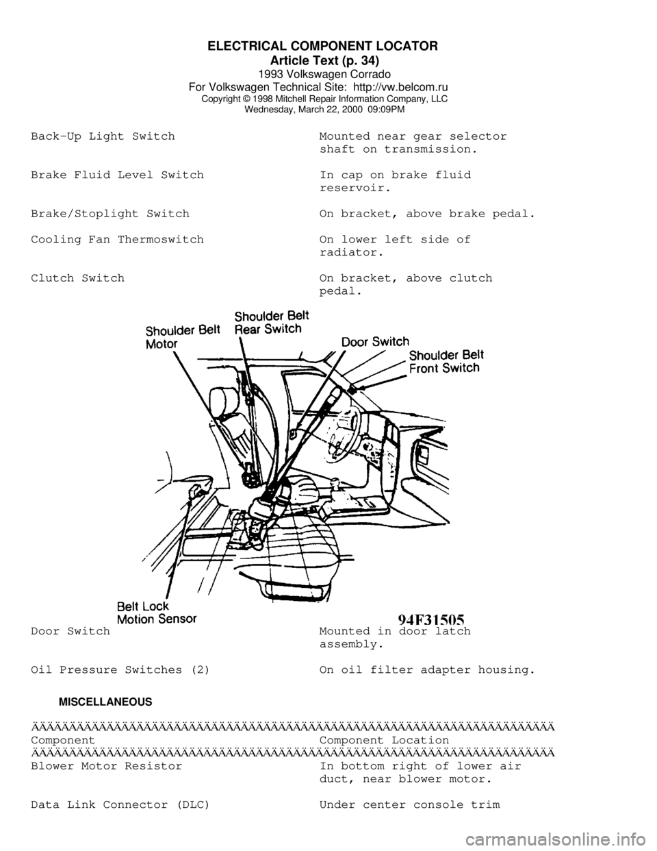
ELECTRICAL COMPONENT LOCATOR
Article Text (p. 34)
1993 Volkswagen Corrado
For Volkswagen Technical Site: http://vw.belcom.ru
Copyright © 1998 Mitchell Repair Information Company, LLC
Wednesday, March 22, 2000 09:09PM
Back-Up Light Switch Mounted near gear selector
shaft on transmission.
Brake Fluid Level Switch In cap on brake fluid
reservoir.
Brake/Stoplight Switch On bracket, above brake pedal.
Cooling Fan Thermoswitch On lower left side of
radiator.
Clutch Switch On bracket, above clutch
pedal.Door Switch Mounted in door latch
assembly.
Oil Pressure Switches (2) On oil filter adapter housing.
MISCELLANEOUSÄÄÄÄÄÄÄÄÄÄÄÄÄÄÄÄÄÄÄÄÄÄÄÄÄÄÄÄÄÄÄÄÄÄÄÄÄÄÄÄÄÄÄÄÄÄÄÄÄÄÄÄÄÄÄÄÄÄÄÄÄÄÄÄÄÄÄÄÄÄComponent Component Location
ÄÄÄÄÄÄÄÄÄÄÄÄÄÄÄÄÄÄÄÄÄÄÄÄÄÄÄÄÄÄÄÄÄÄÄÄÄÄÄÄÄÄÄÄÄÄÄÄÄÄÄÄÄÄÄÄÄÄÄÄÄÄÄÄÄÄÄÄÄÄBlower Motor Resistor In bottom right of lower air
duct, near blower motor.
Data Link Connector (DLC) Under center console trim
Page 497 of 920

DEFOGGER - REAR WINDOW
Article Text
1993 Volkswagen Corrado
For Volkswagen Technical Site: http://vw.belcom.ru
Copyright © 1998 Mitchell Repair Information Company, LLC
Wednesday, March 22, 2000 09:08PM
ARTICLE BEGINNING
1993 ACCESSORIES & EQUIPMENT
Volkswagen Rear Window Defoggers
Volkswagen; Cabriolet, Corrado SLC, EuroVan,
Fox, Golf, GTI, Jetta, Passat
DESCRIPTION & OPERATION
Ignition must be on for rear window defogger to operate.
Power to control switch is applied through fuse in fuse block. An
indicator light in the control switch comes on when the defogger is
turned on. Control switch also provides power to heating element in
both outside mirrors.
TROUBLE SHOOTING
DEFOGGER DOES NOT WORK
Check for blown fuse, defective defogger switch, open wiring
or poor connections. Check for breaks in rear window defogger grid.
See FILAMENT TEST under TESTING.
INDICATOR LIGHT DOES NOT WORK
Check for burned bulb, blown fuse, open wiring or poor
connection.
TESTING
SYSTEM TEST
Ensure and control switch are okay. Turn ignition and control
switch on. After a few minutes, feel glass for warmth. If glass is not
warm, use a test light to check for battery voltage at grid feed wire.
If no voltage is present, check control switch.
FILAMENT TEST
1) To locate breaks in grid filaments, connect test light
negative lead to ground side of grid. Touch opposite (positive) side
of grid with test light probe. If test light glows, grid line is okay.
Test light will glow dimmer as probe is moved toward ground side of
grid.
2) If test light does not glow, grid line is broken. To
locate break, move probe along grid line toward ground side of heat
grid until test light glows, indicating area of damage.
WIRING DIAGRAMS
Page 509 of 920

E - THEORY/OPERATION
Article Text (p. 4)
1993 Volkswagen Corrado
For Volkswagen Technical Site: http://vw.belcom.ru
Copyright © 1998 Mitchell Repair Information Company, LLC
Wednesday, March 22, 2000 09:09PM
Fuel Injectors
See FUEL CONTROL under FUEL SYSTEM in this article.
Fuel Pump
See FUEL DELIVERY under FUEL SYSTEM in this article.
Idle Air Control/Stabilizer Valve
See IDLE SPEED under FUEL SYSTEM in this article.
Ignition Coil & Output Stage
See DISTRIBUTORLESS IGNITION SYSTEM (DIS) under IGNITION
SYSTEM in this article.
Malfunction Indicator (CHECK ENGINE) Light
See MALFUNCTION INDICATOR (CHECK ENGINE) LIGHT under SELF-
DIAGNOSTIC SYSTEM in this article.
FUEL SYSTEM
FUEL DELIVERY
Fuel Pump
A 2-stage fuel pump, located in fuel tank, is used (one motor
drives two separate pumps). The stage one vane-type pump draws fuel,
through a screen, from bottom of fuel tank and into an accumulator.
The vane-type pump acts as a transfer pump. The stage two gear-type
pump draws fuel from bottom of accumulator and out fuel lines.
Fuel Pressure Regulator
The diaphragm-type fuel pressure regulator is attached to
fuel return side of fuel rail. Fuel pressure is regulated depending on
intake manifold pressure. As intake manifold pressure changes, the
pressure regulator will increase or decrease fuel system pressure.
FUEL CONTROL
Fuel Injectors
Fuel injectors are supplied with battery (system) voltage
through power supply relay and are controlled (grounded) by the ECM.
Injectors are opened sequentially in cylinder firing order. Fuel
quantity is determined by injector on time (duty cycle).
IDLE SPEED
Idle Air Control/Stabilizer Valve
The idle air control/stabilizer valve is actuated by the ECM
thorough the valve's ground control circuit. When a defect in circuit
is recognized, both output stages are shut-off and the valve rotates
to a fixed potion. This permits engine to idle at a warm engine idle
speed.
IGNITION SYSTEM