1993 VOLKSWAGEN CORRADO light
[x] Cancel search: lightPage 561 of 920
ENGINE OVERHAUL PROCEDURES - GENERAL INFORMATION
Article Text (p. 32)
1993 Volkswagen Corrado
For Volkswagen Technical Site: http://vw.belcom.ru
Copyright © 1998 Mitchell Repair Information Company, LLC
Wednesday, March 22, 2000 09:10PM
zero. Rotate camshaft gear in opposite direction as far as possible
and note reading.
To determine timing gear runout, mount dial indicator with
tip resting on face edge of camshaft gear. Adjust indicator to zero.
Rotate camshaft gear 360 degrees and note reading. If backlash or
runout exceed specifications, replace camshaft and/or crankshaft
gear.
REAR MAIN OIL SEAL
* PLEASE READ THIS FIRST *
NOTE: Always refer to appropriate engine overhaul article in the
ENGINES section for complete overhaul procedures and
specifications for the vehicle being repaired.
INSTALLATION
One-Piece Type Seal
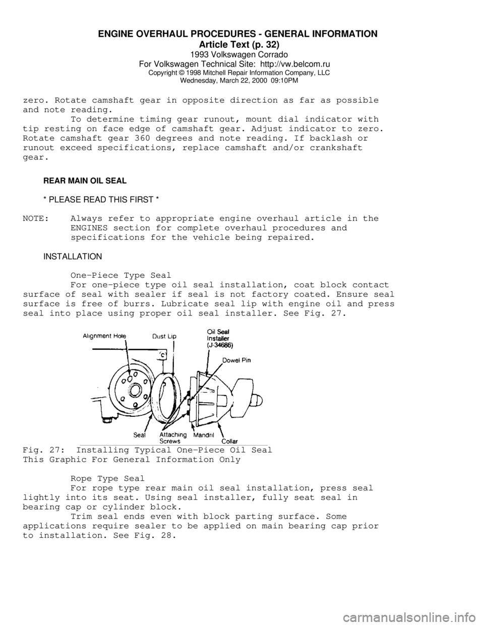
For one-piece type oil seal installation, coat block contact
surface of seal with sealer if seal is not factory coated. Ensure seal
surface is free of burrs. Lubricate seal lip with engine oil and press
seal into place using proper oil seal installer. See Fig. 27.Fig. 27: Installing Typical One-Piece Oil Seal
This Graphic For General Information Only
Rope Type Seal
For rope type rear main oil seal installation, press seal
lightly into its seat. Using seal installer, fully seat seal in
bearing cap or cylinder block.
Trim seal ends even with block parting surface. Some
applications require sealer to be applied on main bearing cap prior
to installation. See Fig. 28.
Page 564 of 920
ENGINE OVERHAUL PROCEDURES - GENERAL INFORMATION
Article Text (p. 35)
1993 Volkswagen Corrado
For Volkswagen Technical Site: http://vw.belcom.ru
Copyright © 1998 Mitchell Repair Information Company, LLC
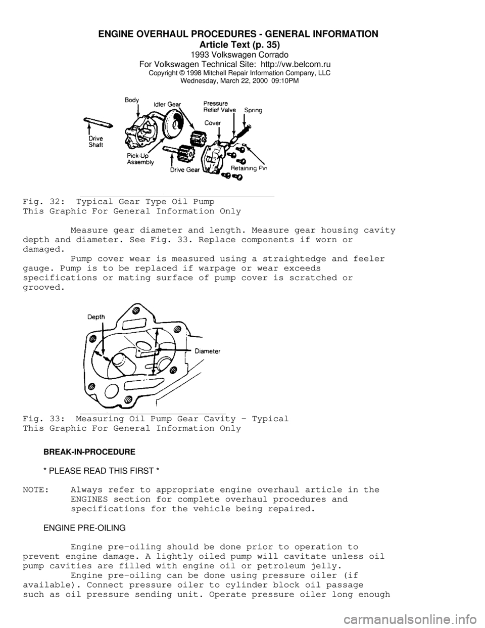
Wednesday, March 22, 2000 09:10PMFig. 32: Typical Gear Type Oil Pump
This Graphic For General Information Only
Measure gear diameter and length. Measure gear housing cavity
depth and diameter. See Fig. 33. Replace components if worn or
damaged.
Pump cover wear is measured using a straightedge and feeler
gauge. Pump is to be replaced if warpage or wear exceeds
specifications or mating surface of pump cover is scratched or
grooved.Fig. 33: Measuring Oil Pump Gear Cavity - Typical
This Graphic For General Information Only
BREAK-IN-PROCEDURE
* PLEASE READ THIS FIRST *
NOTE: Always refer to appropriate engine overhaul article in the
ENGINES section for complete overhaul procedures and
specifications for the vehicle being repaired.
ENGINE PRE-OILING
Engine pre-oiling should be done prior to operation to
prevent engine damage. A lightly oiled pump will cavitate unless oil
pump cavities are filled with engine oil or petroleum jelly.
Engine pre-oiling can be done using pressure oiler (if
available). Connect pressure oiler to cylinder block oil passage
such as oil pressure sending unit. Operate pressure oiler long enough
Page 569 of 920
F - BASIC TESTING
Article Text (p. 4)
1993 Volkswagen Corrado
For Volkswagen Technical Site: http://vw.belcom.ru
Copyright © 1998 Mitchell Repair Information Company, LLC
Wednesday, March 22, 2000 09:10PM
kg/cmý). Turn engine off. After 10 minutes, residual pressure should
be 29 psi (2 kg/cm
ý). If system pressure is too high, replace fuel
pressure regulator.
3) If residual pressure is too low, operate engine until
system pressure builds up, then pinch off Blue fuel return line. If
pressure holds, replace the fuel regulator. If fuel pressure is low,
check for leaks at fuel lines, fuel injectors and fuel pump check
valve
TRANSFER PUMP CHECK
Transfer Pump Fuel Volume Check
1) Turn ignition off. To check transfer pump (in tank),
remove rear seat. Remove fuel sending unit access cover. Disconnect
ignition coil secondary wire and jumper to ground.
2) With transmission in Neutral, crank engine for 3-4
seconds. While starter is turning and for a few seconds afterwards, an
audible sound should be heard at the pump. If sound is not heard, go
to next step. If sound is heard, go to step 5).
3) Remove fuel pump relay from relay panel. On Corrado and
Passat, activate fuel pumps using Remote Control (VAG 1348/3A). On all
other models, activate fuel pumps using Remote Control (US 4480/3). On
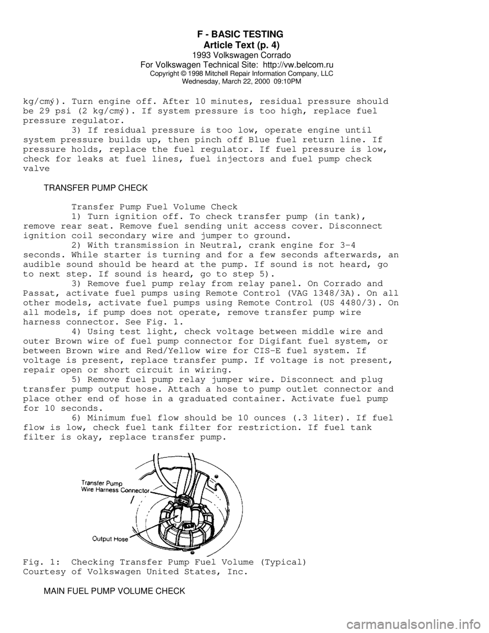
all models, if pump does not operate, remove transfer pump wire
harness connector. See Fig. 1.
4) Using test light, check voltage between middle wire and
outer Brown wire of fuel pump connector for Digifant fuel system, or
between Brown wire and Red/Yellow wire for CIS-E fuel system. If
voltage is present, replace transfer pump. If voltage is not present,
repair open or short circuit in wiring.
5) Remove fuel pump relay jumper wire. Disconnect and plug
transfer pump output hose. Attach a hose to pump outlet connector and
place other end of hose in a graduated container. Activate fuel pump
for 10 seconds.
6) Minimum fuel flow should be 10 ounces (.3 liter). If fuel
flow is low, check fuel tank filter for restriction. If fuel tank
filter is okay, replace transfer pump.Fig. 1: Checking Transfer Pump Fuel Volume (Typical)
Courtesy of Volkswagen United States, Inc.
MAIN FUEL PUMP VOLUME CHECK
Page 572 of 920
F - BASIC TESTING
Article Text (p. 7)
1993 Volkswagen Corrado
For Volkswagen Technical Site: http://vw.belcom.ru
Copyright © 1998 Mitchell Repair Information Company, LLC
Wednesday, March 22, 2000 09:10PM
Digifant II ......... 0.52-0.76 ........ 2400-3500
Corrado SLC (1) ........ ..... .............. .....
Fox
Digifant I ........... 0.5-0.7 ......... 3000-4000
Digifant II .......... 0.6-0.7 ......... 2500-3500
Golf, GTI & Jetta ..... 0.5-0.7 ......... 3000-4000
Passat GL ............. 0.6-0.8 ......... 6500-8500
Passat GLX (1) ......... ..... .............. .....
(1) - Ignition coil pack, new for 1993, is located on
left side of cylinder head. When ignition coil is
triggered, spark is supplied to 2 spark plugs at
one time. One spark plug fires during compression
stroke and the other plug fires during exhaust
stroke (waste spark). Ignition coil specifications
are not available from manufacturer.ÄÄÄÄÄÄÄÄÄÄÄÄÄÄÄÄÄÄÄÄÄÄÄÄÄÄÄÄÄÄÄÄÄÄÄÄÄÄÄÄÄÄÄÄÄÄÄÄÄÄÄÄÄÄÄ DISTRIBUTOR
Hall Effect Sender
1) Remove coil secondary wire and attach to ground.
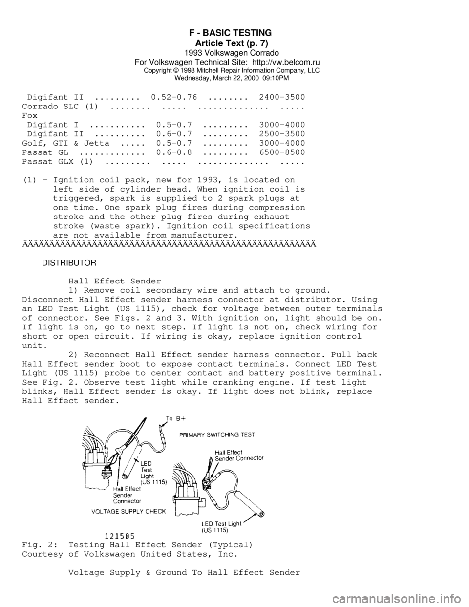
Disconnect Hall Effect sender harness connector at distributor. Using
an LED Test Light (US 1115), check for voltage between outer terminals
of connector. See Figs. 2 and 3. With ignition on, light should be on.
If light is on, go to next step. If light is not on, check wiring for
short or open circuit. If wiring is okay, replace ignition control
unit.
2) Reconnect Hall Effect sender harness connector. Pull back
Hall Effect sender boot to expose contact terminals. Connect LED Test
Light (US 1115) probe to center contact and battery positive terminal.
See Fig. 2. Observe test light while cranking engine. If test light
blinks, Hall Effect sender is okay. If light does not blink, replace
Hall Effect sender.Fig. 2: Testing Hall Effect Sender (Typical)
Courtesy of Volkswagen United States, Inc.
Voltage Supply & Ground To Hall Effect Sender
Page 579 of 920
FUSES & CIRCUIT BREAKERS
Article Text
1993 Volkswagen Corrado
For Volkswagen Technical Site: http://vw.belcom.ru
Copyright © 1998 Mitchell Repair Information Company, LLC
Wednesday, March 22, 2000 09:11PM
ARTICLE BEGINNING
1990-94 ELECTRICAL
Volkswagen Fuses & Circuit Breakers
Corrado
FUSES & CIRCUIT BREAKERS
FUSE PANEL LOCATION
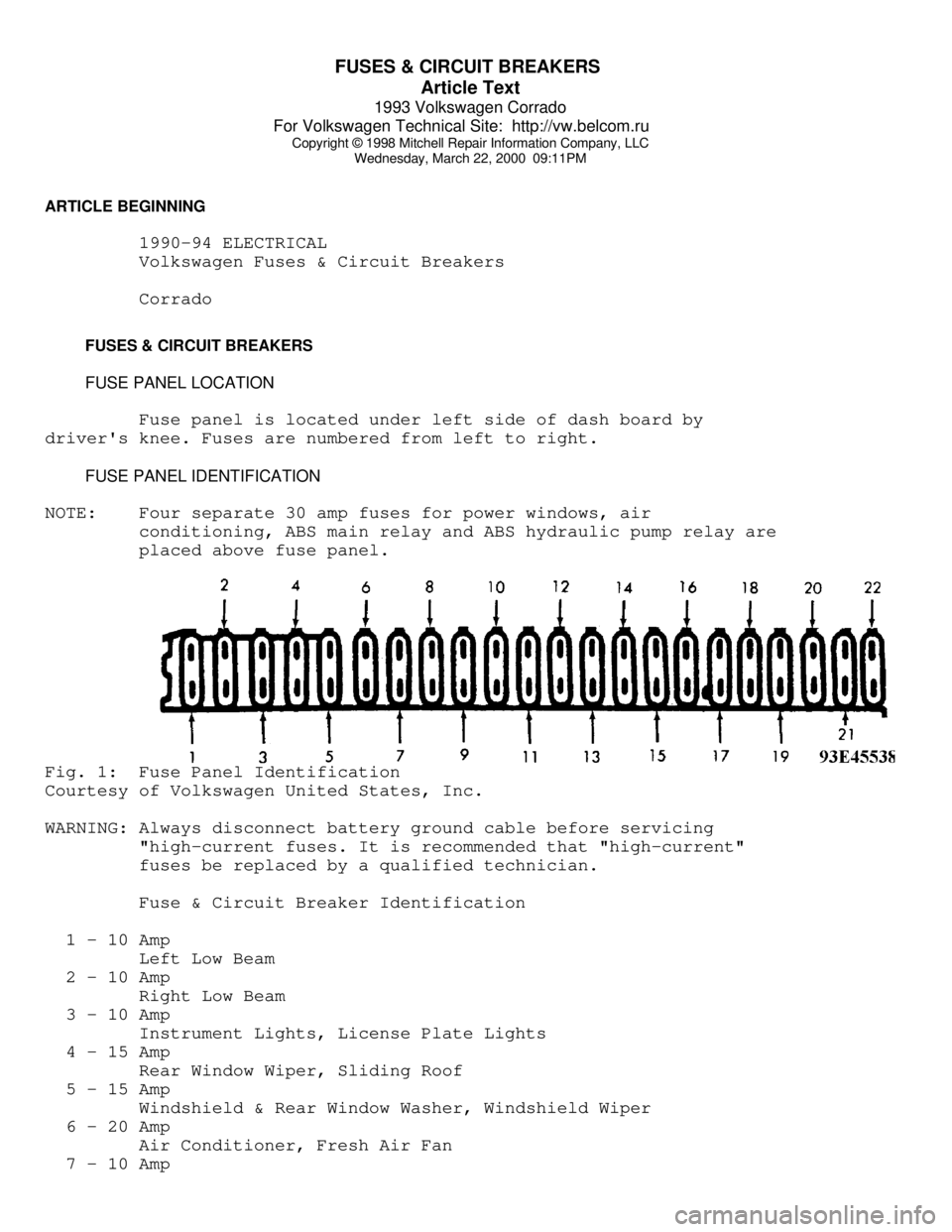
Fuse panel is located under left side of dash board by
driver's knee. Fuses are numbered from left to right.
FUSE PANEL IDENTIFICATION
NOTE: Four separate 30 amp fuses for power windows, air
conditioning, ABS main relay and ABS hydraulic pump relay are
placed above fuse panel.Fig. 1: Fuse Panel Identification
Courtesy of Volkswagen United States, Inc.
WARNING: Always disconnect battery ground cable before servicing
"high-current fuses. It is recommended that "high-current"
fuses be replaced by a qualified technician.
Fuse & Circuit Breaker Identification
1 - 10 Amp
Left Low Beam
2 - 10 Amp
Right Low Beam
3 - 10 Amp
Instrument Lights, License Plate Lights
4 - 15 Amp
Rear Window Wiper, Sliding Roof
5 - 15 Amp
Windshield & Rear Window Washer, Windshield Wiper
6 - 20 Amp
Air Conditioner, Fresh Air Fan
7 - 10 Amp
Page 580 of 920

FUSES & CIRCUIT BREAKERS
Article Text (p. 2)
1993 Volkswagen Corrado
For Volkswagen Technical Site: http://vw.belcom.ru
Copyright © 1998 Mitchell Repair Information Company, LLC
Wednesday, March 22, 2000 09:11PM
Right Tail & Side Lights
8 - 10 Amp
Left Tail & Side Lights
9 - 20 Amp
Rear Window & Mirror Heating
10 - 15 Amp
Foglights
11 - 10 Amp
Left High Beam, High Beam Indicator
12 - 10 Amp
Right High Beam
13 - 10 Amp
Horn, Radiator Fan
14 - 15 Amp
Back-Up Lights, Electric Mirrors, Heated Windshield Washer
Jets
15 - 10 Amp
Engine Electronic
16 - 15 Amp
Warning/Indicator Lights, Multi-Function Indicator, Glove Box
Light, Cassette Storage Light, Rear Spoiler
17 - 10 Amp
Turn Signals
18 - 20 Amp
Fuel Pump, Oxygen Sensor
19 - 30 Amp
Radiator Fan, Air Conditioner
20 - 10 Amp
Brakelights, Cruise Control
21 - 15 Amp
Dome & Luggage Compartment Lights, Cigarette Lighter, Central
Locking System, Multi-Function Indicator
22 - 10 Amp
Radio
CAUTIONS & WARNINGS
ELECTRICAL SHOCK
WARNING: Contact with live components of ignition system while
engine is running could lead to a fatal electric shock.
RADIATOR FAN
Keep hands away from radiator fan. Fan is controlled by a
thermostatic switch which may come on or run for up to 15 minutes even
after engine is turned off.
RADIATOR CAP
CAUTION: Always disconnect the fan motor when working near the
radiator fan. The fan is temperature controlled and could
Page 581 of 920

FUSES & CIRCUIT BREAKERS
Article Text (p. 3)
1993 Volkswagen Corrado
For Volkswagen Technical Site: http://vw.belcom.ru
Copyright © 1998 Mitchell Repair Information Company, LLC
Wednesday, March 22, 2000 09:11PM
start at any time even when the ignition key is in the OFF
position. DO NOT loosen or remove radiator cap when cooling
system is hot.
REPLACING BLOWN FUSES
Before replacing a blown fuse, remove ignition key, turn off
all lights and accessories to avoid damaging the electrical system. Be
sure to use fuse with the correct indicated amperage rating. The use
of an incorrect amperage rating fuse may result in a dangerous
electrical system overload.
BATTERY WARNING
WARNING: When battery is disconnected, vehicles equipped with
computers may lose memory data. When battery power is
restored, driveability problems may exist on some vehicles.
These vehicles may require a relearn procedure. See COMPUTER
RELEARN PROCEDURES article in GENERAL INFORMATION section.
BRAKE PAD WEAR INDICATOR
Indicator will cause a squealing or scraping noise, warning
that brake pads need replacement.
HALOGEN BULBS
Halogen bulbs contain pressurized gas which may explode if
overheated. DO NOT touch glass portion of bulb with bare hands. Eye
protection should be worn when handling or working around halogen
bulbs.
SUPPLEMENTAL RESTRAINT SYSTEM (AIR BAG)
NOTE: See the AIR BAGS article in the ACCESSORIES/SAFETY EQUIPMENT
Section.
Modifications or improper maintenance, including incorrect
removal and installation of the Supplemental Restraint System (SRS),
can adversely affect system performance. DO NOT cover, obstruct or
change the steering wheel horn pad in any way, as such action could
cause improper function of the system. Use only plain water when
cleaning the horn pad. Solvents or cleaners could adversely affect the
air bag cover and cause improper deployment of the system.
WARNING: To avoid injury from accidental air bag deployment, read and
carefully follow all warnings and service precautions. See
appropriate AIR BAGS article in ACCESSORIES/SAFETY EQUIPMENT.
CAUTION: Disconnect negative battery cable before servicing any air
bag system, steering column or passenger side dash
component. After any repair, turn ignition key to the ON
Page 583 of 920

G - TESTS W/CODES
Article Text
1993 Volkswagen Corrado
For Volkswagen Technical Site: http://vw.belcom.ru
Copyright © 1998 Mitchell Repair Information Company, LLC
Wednesday, March 22, 2000 09:11PM
ARTICLE BEGINNING
1993 ENGINE PERFORMANCE
Volkswagen Self-Diagnostics
Corrado SLC
INTRODUCTION
If no faults were found while performing preliminary
inspection procedures, proceed with self-diagnostics. If no fault
codes or only pass codes are present after entering self-diagnostics,
proceed to H - TESTS W/O CODES article for diagnosis by symptom (i.e.,
ROUGH IDLE, NO START, etc.).
NOTE: Scan Tester (VAG 1551) must be used to make full use of the
self-diagnostic system capabilities.
SELF-DIAGNOSTIC SYSTEM DESCRIPTION
Hard Failures
Hard failures of monitored sensors and/or components, cause
Malfunction Indicator Light (MIL) to come on and remain on until
problem is repaired. If malfunction indicator CHECK ENGINE light comes
on and remains on during vehicle operation, cause of malfunction must
be determined.
If malfunctions are present for more than 5 seconds, they are
stored as Diagnostic Trouble Codes (DTCs) and will be displayed as a
permanent malfunction even though the malfunction is not occurring at
the time DTCs are displayed. Malfunctions that affect oxygen sensor
control can only be read accurately after a test drive of at least 5
minutes.
Intermittent Failures
If a malfunction occurs for a maximum of 5 seconds, they are
stored and considered to be "sporadic" (intermittent failures). When
displayed on scan tester, malfunctions will have "SP" (sporadic) code.
RETRIEVING CODES
NOTE: See ENTERING SELF-DIAGNOSTICS for additional scan tester
operating instructions.
Corrado SLC
1) Turn ignition on. Connect Jumper Cable (357 971 514E) to
Data Link Connectors (DLC) located in center console. See Fig. 1.
Black end of jumper cable attaches to Black data link connector; White
end of cable attaches to White connector.
2) Leave jumper cable attached for 5 seconds, until on-board
diagnostic CHECK ENGINE light begins to blink. Remove jumper cable.
Allow on-board diagnostic code retrieval procedure to run until Code