1993 VOLKSWAGEN CORRADO reset
[x] Cancel search: resetPage 2 of 920

HOW TO USE SYSTEM WIRING DIAGRAMSI - SYSTEM/COMPONENT TESTSINSTRUMENT PANELINTERFERENCE VERIFICATION CHECK FOR OHC ENGINEJ - PIN VOLTAGE CHARTSL - WIRING DIAGRAMSM - VACUUM DIAGRAMSMAINTENANCE INFORMATIONMAINTENANCE REMINDER LIGHT RESET PROCEDURESMETRIC CONVERSIONSMIRRORS - POWERN - REMOVE/INSTALL/OVERHAULP - EGR FUNCTION TESTINGPRE-ALIGNMENT CHECKSRIDING HEIGHT ADJUSTMENTSCHEDULED SERVICESSPECIFICATIONS & ELECTRIC COOLING FANSSTARTERSTEERING COLUMNSTEERING COLUMN SWITCHESSTEERING GEAR - POWER RACK & PINIONSUN ROOF - POWERSUSPENSION - FRONTSUSPENSION - REARSYSTEM WIRING DIAGRAMSTRANSMISSION REMOVAL & INSTALLATION - A/TTRANSMISSION REMOVAL & INSTALLATION - M/TTRANSMISSION SERVICING - A/TTRANSMISSION SERVICING - M/TTROUBLE SHOOTING - BASIC PROCEDURESVR65 ENGINE: AFFIX NEW VACUUM HOSE ROUTING LABELWAVEFORMS - INJECTOR PATTERN TUTORIALWHEEL ALIGNMENT SPECIFICATIONS & PROCEDURESWHEEL ALIGNMENT THEORY/OPERATIONWIPER/WASHER SYSTEMWIRING DIAGRAM SYMBOLSWIRING DIAGRAMSWIRING HARNESS CHAFING MAY CAUSE ENGINE STALL
Page 378 of 920

A/C-HEATER SYSTEM - MANUAL
Article Text (p. 3)
1993 Volkswagen Corrado
For Volkswagen Technical Site: http://vw.belcom.ru
Copyright © 1998 Mitchell Repair Information Company, LLC
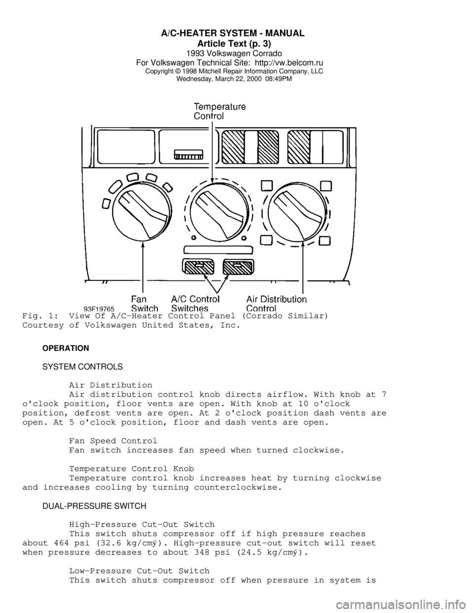
Wednesday, March 22, 2000 08:49PMFig. 1: View Of A/C-Heater Control Panel (Corrado Similar)
Courtesy of Volkswagen United States, Inc.
OPERATION
SYSTEM CONTROLS
Air Distribution
Air distribution control knob directs airflow. With knob at 7
o'clock position, floor vents are open. With knob at 10 o'clock
position, defrost vents are open. At 2 o'clock position dash vents are
open. At 5 o'clock position, floor and dash vents are open.
Fan Speed Control
Fan switch increases fan speed when turned clockwise.
Temperature Control Knob
Temperature control knob increases heat by turning clockwise
and increases cooling by turning counterclockwise.
DUAL-PRESSURE SWITCH
High-Pressure Cut-Out Switch
This switch shuts compressor off if high pressure reaches
about 464 psi (32.6 kg/cmý). High-pressure cut-out switch will reset
when pressure decreases to about 348 psi (24.5 kg/cm
ý).
Low-Pressure Cut-Out Switch
This switch shuts compressor off when pressure in system is
Page 392 of 920

AA - USING THIS SECTION (GENERAL HELP INFORMATION)
Article Text (p. 6)
1993 Volkswagen Corrado
For Volkswagen Technical Site: http://vw.belcom.ru
Copyright © 1998 Mitchell Repair Information Company, LLC
Wednesday, March 22, 2000 08:49PM
1) If no self-diagnostics available, or no trouble codes
present, identify symptom.
2) See trouble shooting procedure to repair complaint. See H
- TESTS W/O CODES
TEST SYSTEM
1) Perform necessary systems and component tests. See I -
SYS/COMP TESTS.
2) Verify that complaint is repaired.
SAFETY PRECAUTIONS
* Always refer to Engine Tune-Up Decal in engine compartment before
performing tune-up. If manual and decal differ, always use decal
specifications.
* DO NOT allow or create a condition of misfire in more than one
cylinder for an extended period of time. Damage to converter may
occur due to loading converter with unburned air/fuel mixture.
* Always turn ignition off and disconnect negative battery cable
BEFORE disconnecting or connecting computer or other electrical
components.
* DO NOT drop or shock electrical components such as computer,
airflow meter, etc.
* DO NOT use fuel system cleaning compounds that are not
recommended by the manufacturer. Damage to gaskets, diaphragm
materials and catalytic converter may result.
* Before performing a compression test or cranking engine using a
remote starter switch, disconnect coil wire from distributor and
secure it to a good engine ground, or disable ignition.
* Before disconnecting any fuel system component, ensure fuel
system pressure is released.
* Use a shop towel to absorb any spilled fuel to prevent fire.
* DO NOT create sparks or have an open flame near battery.
* If any EFI components such as hoses or clamps are replaces,
ensure they are replaced with components designed for EFI use.
* Always reassemble throttle body components with new gaskets, "O"
rings and seals.
* If equipped with an inertia switch, DO NOT reset switch until
fuel system has been inspected for leaks.
* Wear safety goggles when drilling or grinding.
* Wear proper clothing which protects against chemicals and other
hazards.
END OF ARTICLE
Page 528 of 920

EMISSION CONTROL VISUAL INSPECTION PROCEDURES
Article Text (p. 14)
1993 Volkswagen Corrado
For Volkswagen Technical Site: http://vw.belcom.ru
Copyright © 1998 Mitchell Repair Information Company, LLC
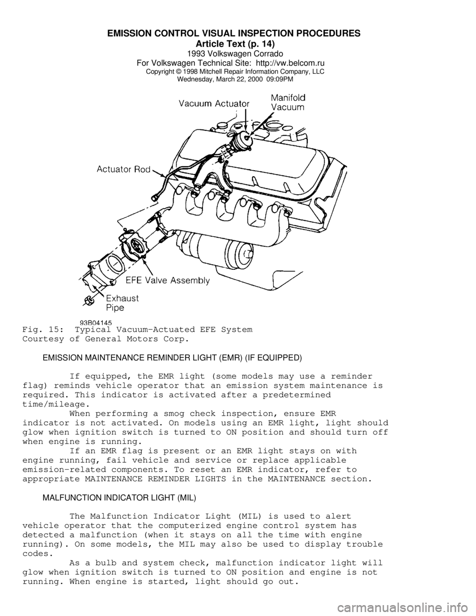
Wednesday, March 22, 2000 09:09PMFig. 15: Typical Vacuum-Actuated EFE System
Courtesy of General Motors Corp.
EMISSION MAINTENANCE REMINDER LIGHT (EMR) (IF EQUIPPED)
If equipped, the EMR light (some models may use a reminder
flag) reminds vehicle operator that an emission system maintenance is
required. This indicator is activated after a predetermined
time/mileage.
When performing a smog check inspection, ensure EMR
indicator is not activated. On models using an EMR light, light should
glow when ignition switch is turned to ON position and should turn off
when engine is running.
If an EMR flag is present or an EMR light stays on with
engine running, fail vehicle and service or replace applicable
emission-related components. To reset an EMR indicator, refer to
appropriate MAINTENANCE REMINDER LIGHTS in the MAINTENANCE section.
MALFUNCTION INDICATOR LIGHT (MIL)
The Malfunction Indicator Light (MIL) is used to alert
vehicle operator that the computerized engine control system has
detected a malfunction (when it stays on all the time with engine
running). On some models, the MIL may also be used to display trouble
codes.
As a bulb and system check, malfunction indicator light will
glow when ignition switch is turned to ON position and engine is not
running. When engine is started, light should go out.
Page 622 of 920

INSTRUMENT PANEL
Article Text (p. 3)
1993 Volkswagen Corrado
For Volkswagen Technical Site: http://vw.belcom.ru
Copyright © 1998 Mitchell Repair Information Company, LLC
Wednesday, March 22, 2000 09:12PM
Corrado SLC ................... 80 ........................ Normal
50 ....................... (2) Hot
(1) - Information for EuroVan not available from manufacturer.
(2) - With Red LED flashing.ÄÄÄÄÄÄÄÄÄÄÄÄÄÄÄÄÄÄÄÄÄÄÄÄÄÄÄÄÄÄÄÄÄÄÄÄÄÄÄÄÄÄÄÄÄÄÄÄÄÄÄÄÄÄÄÄÄÄÄÄÄÄÄÄÄÄÄÄÄÄ REMOVAL & INSTALLATION
CAUTION: DO NOT damage printed circuit when installing instruments.
INSTRUMENT CLUSTER
Removal & Installation
1) Obtain radio code. Disconnect negative battery cable.
Remove steering wheel only when removing complete instrument cluster
housing. Remove trim screw caps and screws located on lower part of
instrument cluster trim. Remove instrument cluster trim.
2) Remove trip odometer reset button. Remove trim cover
retaining screws. Remove trim cover from instrument cluster. Remove
instrument cluster housing retaining screws. Pull instrument cluster
from dash panel. Disconnect multi-point connector, MFI vacuum hose (if
equipped) and speedometer drive cable. Remove instrument cluster
housing.
NOTE: All components in instrument cluster, except for printed
circuit, can be removed from front, without removing
complete instrument cluster housing.
3) Disconnect speedometer cable, remove mounting screws and
pull speedometer from housing. Squeeze locating pins on other
instruments and pull from housing. To install, reverse removal
procedure.
Page 669 of 920

MAINTENANCE REMINDER LIGHT RESET PROCEDURES
Article Text
1993 Volkswagen Corrado
For Volkswagen Technical Site: http://vw.belcom.ru
Copyright © 1998 Mitchell Repair Information Company, LLC
Wednesday, March 22, 2000 09:20PM
ARTICLE BEGINNING
1983-96 MAINTENANCE
Volkswagen Maintenance Reminder Light Reset Procedures
EGR MAINTENANCE LIGHT (IF EQUIPPED)
EGR light comes on at 15,000 mile intervals to indicate EGR
servicing is required. After checking EGR system, reset mileage
counter. See RESETTING MILEAGE COUNTER.
OXYGEN SENSOR WARNING LIGHT (IF EQUIPPED)
Oxygen sensor (OXS) light comes on at 30,000 mile intervals
to indicate oxygen sensor replacement. After installing new sensor,
reset mileage counter. See RESETTING MILEAGE COUNTER.
RESETTING MILEAGE COUNTER (IF EQUIPPED)
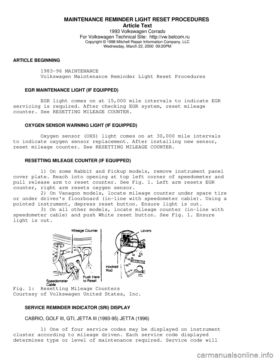
1) On some Rabbit and Pickup models, remove instrument panel
cover plate. Reach into opening at top left corner of speedometer and
pull release arm to reset counter. See Fig. 1. Left arm resets EGR
counter, right arm resets oxygen sensor.
2) On Vanagon models, locate mileage counter under spare tire
or under driver's floorboard (in-line with speedometer cable). Using a
pointed instrument, depress reset button. Ensure light is out.
3) On all other models, locate mileage counter (in-line with
speedometer cable) and push White reset button. See Fig. 1. Ensure
light is out.Fig. 1: Resetting Mileage Counters
Courtesy of Volkswagen United States, Inc.
SERVICE REMINDER INDICATOR (SRI) DISPLAY
CABRIO, GOLF III, GTI, JETTA III (1993-95) JETTA (1996)
1) One of four service codes may be displayed on instrument
cluster according to mileage driven. Each service code displayed
determines type or level of maintenance required. Service code will
Page 670 of 920

MAINTENANCE REMINDER LIGHT RESET PROCEDURES
Article Text (p. 2)
1993 Volkswagen Corrado
For Volkswagen Technical Site: http://vw.belcom.ru
Copyright © 1998 Mitchell Repair Information Company, LLC
Wednesday, March 22, 2000 09:20PM
flash for approximately 3 seconds in odometer display window as
ignition is turned on. When servicing becomes due (every 7500 miles),
appropriate service code will flash for approximately 60 seconds. The
four service codes available for display are as follows:
* IN 00 (No Service Necessary)
* OEL (Oil Change Service) Every 7500 Miles
* IN 01 (Inspection Service) Every 15,000 Miles
* IN 02 (Additional Servicing Work) Every 30,000 Miles
2) After performing required maintenance, each effected
service code displayed must be reset individually. For example, at 15,
000 miles service codes OEL and IN 01 will both need to be reset.
3) To reset service codes, turn ignition on. Press and hold
odometer reset button located below speedometer. While holding button,
press clock reset button (lower button for digital clock) located to
left of fuel gauge. Release buttons. Programming mode is now
activated. Service code OEL1.S (distance counter) should be displayed.
4) Press clock reset button once more. 7500 miles should now
be indicated on display. Desired mileage for reset may be attained by
pressing clock reset button. Mileage displayed will decrease in
increments of 500 miles each time button is pressed. This feature
should only be used to calibrate mileage when instrument cluster is
replaced. When desired mileage is displayed, press odometer reset
button.
5) Service code OEL2.S (time counter) should be displayed.
Press clock reset button. 6 (months) will be indicated on display.
Time counter for next oil change may be set by pressing clock reset
button if instrument cluster was replaced. When desired time is
displayed, press odometer reset button.
6) Service code IN 01.S (time counter) should be displayed.
Press clock reset button. 12 (months) will be indicated on display.
Time counter for next maintenance interval may be set by pressing
clock reset button if instrument cluster was replaced. When desired
time is displayed, press odometer reset button.
7) Service code IN 02.S (distance counter) should be
displayed. Press clock reset button. 30,000 (miles) will be indicated
on display. Desired mileage for reset may be attained by pressing
clock reset button. Mileage displayed will decrease in increments of
500 miles each time button is pressed. This feature should only be
used to calibrate mileage when instrument cluster is replaced. When
desired mileage is displayed, turn ignition off. Programming is now
stored in memory.
END OF ARTICLE
Page 796 of 920

TROUBLE SHOOTING - BASIC PROCEDURES
Article Text (p. 5)
1993 Volkswagen Corrado
For Volkswagen Technical Site: http://vw.belcom.ru
Copyright © 1998 Mitchell Repair Information Company, LLC
Wednesday, March 22, 2000 09:25PM
Binding brake pedal See DISC, DRUM BRAKES
or BRAKE SYSTEMÄÄÄÄÄÄÄÄÄÄÄÄÄÄÄÄÄÄÄÄÄÄÄÄÄÄÄÄÄÄÄÄÄÄÄÄÄÄÄÄÄÄÄÄÄÄÄÄÄÄÄÄÄÄÄÄÄÄÄÄÄÄÄÄÄÄÄÄÄÄPulsation or
Roughness Uneven pad wear caused by See DISC BRAKES or
caliper BRAKE SYSTEM
Uneven rotor wear See DISC BRAKES or
BRAKE SYSTEM
Drums out-of-round Reface or replace drums
ÄÄÄÄÄÄÄÄÄÄÄÄÄÄÄÄÄÄÄÄÄÄÄÄÄÄÄÄÄÄÄÄÄÄÄÄÄÄÄÄÄÄÄÄÄÄÄÄÄÄÄÄÄÄÄÄÄÄÄÄÄÄÄÄÄÄÄÄÄÄ CARBURETOR TROUBLE SHOOTING:
READ THIS FIRST:
WARNING: This is GENERAL information. This article is not intended
to be specific to any unique situation or individual vehicle
configuration. The purpose of this Trouble Shooting
information is to provide a list of common causes to
problem symptoms. For model-specific Trouble Shooting,
refer to SUBJECT, DIAGNOSTIC, or TESTING articles available
in the section(s) you are accessing.
COLD START SYMPTOMS
BASIC COLD START SYMPTOMS TROUBLE SHOOTING CHART
ÄÄÄÄÄÄÄÄÄÄÄÄÄÄÄÄÄÄÄÄÄÄÄÄÄÄÄÄÄÄÄÄÄÄÄÄÄÄÄÄÄÄÄÄÄÄÄÄÄÄÄÄÄÄÄÄÄÄÄÄÄÄÄÄÄÄÄÄÄÄCONDITION POSSIBLE CAUSE CORRECTION
ÄÄÄÄÄÄÄÄÄÄÄÄÄÄÄÄÄÄÄÄÄÄÄÄÄÄÄÄÄÄÄÄÄÄÄÄÄÄÄÄÄÄÄÄÄÄÄÄÄÄÄÄÄÄÄÄÄÄÄÄÄÄÄÄÄÄÄÄÄÄEngine Won't Choke not closing Check choke
Start operation, see
FUEL SYSTEMS
Choke linkage bent Check linkage, see
FUEL SYSTEM
ÄÄÄÄÄÄÄÄÄÄÄÄÄÄÄÄÄÄÄÄÄÄÄÄÄÄÄÄÄÄÄÄÄÄÄÄÄÄÄÄÄÄÄÄÄÄÄÄÄÄÄÄÄÄÄÄÄÄÄÄÄÄÄÄÄÄÄÄÄÄEngine Starts, Choke vacuum kick setting Check setting and
Then Dies too wide adjust see, FUEL
SYSTEMS
Fast idle RPM too low Reset RPM to specif-
ication, see TUNE-UP
Fast idle cam index Reset fast idle cam
incorrect index, see FUEL
SYSTEMS
Vacuum leak Inspect vacuum
system for leaks