1993 VOLKSWAGEN CORRADO lug pattern
[x] Cancel search: lug patternPage 357 of 920

A/C COMPRESSOR SERVICING
Article Text (p. 21)
1993 Volkswagen Corrado
For Volkswagen Technical Site: http://vw.belcom.ru
Copyright © 1998 Mitchell Repair Information Company, LLC
Wednesday, March 22, 2000 08:48PM
cylinder head bolts, in a crisscross pattern, to 21-29 ft. lbs. (29-39
N.m).
SANDEN 5-CYLINDER SHAFT SEAL R & I
Removal
Remove shaft nut and clutch plate. Remove shaft key and
shim(s). Carefully remove felt ring. Remove shaft seal seat snap ring.
Using Seal Seat Remover/Installer (0000-41-0810-73), carefully remove
seal seat. Using Shaft Seal Remover/Installer (0000-41-0812-11),
carefully remove shaft seal.
Installation
1) Install Seal Protector (0000-41-0812-13) over shaft. Place
new seal on remover/installer. DO NOT touch carbon sealing surface
with fingers. Dip seal in refrigerant oil and install. Remove seal
installer by turning counterclockwise.
2) Coat seal seat with refrigerant oil. Install seal seat
using remover/installer. Install seal seat snap ring (with flat side
down). Install shim(s), felt ring and shaft key. Install shaft nut and
clutch plate. Ensure clearance between clutch plate and pulley is .
016-.032" (.40-.80 mm). If clearance is incorrect, add or remove
shim(s) as necessary.
SANDEN 7-CYLINDER CLUTCH COIL AND BEARING R & I
NOTE: Due to variety of clutch and shaft seal configurations,
obtain appropriate A/C compressor service tools for
compressor being serviced.
Removal
1) Install two 6-mm bolts, 1" (25 mm) or longer, in clutch
plate holes. Using 2 box-end wrenches to hold bolts and to prevent
clutch plate from turning, remove shaft nut.
2) Remove clutch plate using Clutch Plate Puller (09977-
21100). Remove clutch shim(s) and bearing dust cover. Remove external
front housing snap ring. See Fig. 18.
3) Remove pulley using universal puller. Detach clutch coil
lead from compressor housing. Remove clutch coil snap ring and clutch
coil. If necessary, remove snap ring and bearing.
Installation
1) Align clutch coil lug with hole in compressor housing, and
install clutch coil. Install clutch coil snap ring. Install drive
pulley using Drive Pulley Installer (09977-21811).
2) Install external bearing snap ring. Using Seal Installer
(09977-21800), install bearing dust cover. After dust cover
installation, ensure there is no contact between cover and front
housing.
3) Install clutch shim(s) and clutch plate. Tighten shaft nut
to 13-14 ft. lbs. (17-19 N.m). Using a dial indicator, check air gap
between clutch plate and drive pulley. Apply voltage to clutch coil.
Page 449 of 920

CLUTCH
Article Text (p. 4)
1993 Volkswagen Corrado
For Volkswagen Technical Site: http://vw.belcom.ru
Copyright © 1998 Mitchell Repair Information Company, LLC
Wednesday, March 22, 2000 08:58PM
* Worn To Surface Of Rivet Heads
* Rivets Are Loose, Missing Or Damaged
* Friction Material Is Oil Or Grease Soaked
* Friction Material Is Loose, Cracked Or Grooved
* Hub Is Rusted Or Damaged
* Springs Are Rusted Solid, Broken, Cracked Or Loose
* Torsion Damper Spring Guide Is Broken
* Torsion Damper Cover Damaged
* Torsion Damper Grooved Or Not Functioning
NOTE: Pressure plate has a protective grease coating. Remove
contact surface grease only. Service life will be shortened
if remaining portions of pressure plate protective grease
are removed.
Installation
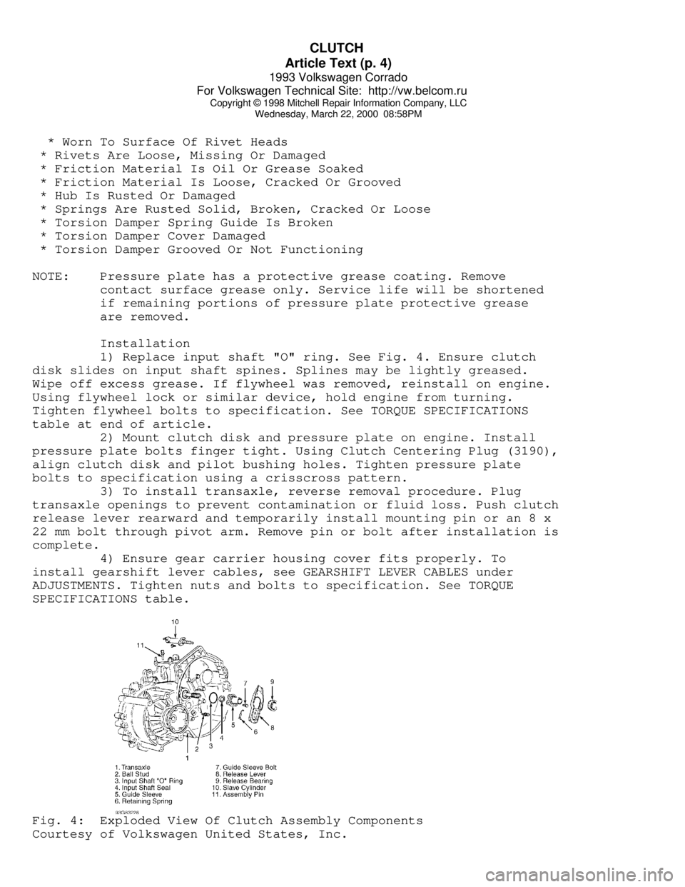
1) Replace input shaft "O" ring. See Fig. 4. Ensure clutch
disk slides on input shaft spines. Splines may be lightly greased.
Wipe off excess grease. If flywheel was removed, reinstall on engine.
Using flywheel lock or similar device, hold engine from turning.
Tighten flywheel bolts to specification. See TORQUE SPECIFICATIONS
table at end of article.
2) Mount clutch disk and pressure plate on engine. Install
pressure plate bolts finger tight. Using Clutch Centering Plug (3190),
align clutch disk and pilot bushing holes. Tighten pressure plate
bolts to specification using a crisscross pattern.
3) To install transaxle, reverse removal procedure. Plug
transaxle openings to prevent contamination or fluid loss. Push clutch
release lever rearward and temporarily install mounting pin or an 8 x
22 mm bolt through pivot arm. Remove pin or bolt after installation is
complete.
4) Ensure gear carrier housing cover fits properly. To
install gearshift lever cables, see GEARSHIFT LEVER CABLES under
ADJUSTMENTS. Tighten nuts and bolts to specification. See TORQUE
SPECIFICATIONS table.Fig. 4: Exploded View Of Clutch Assembly Components
Courtesy of Volkswagen United States, Inc.
Page 787 of 920

TRANSMISSION REMOVAL & INSTALLATION - M/T
Article Text (p. 3)
1993 Volkswagen Corrado
For Volkswagen Technical Site: http://vw.belcom.ru
Copyright © 1998 Mitchell Repair Information Company, LLC
Wednesday, March 22, 2000 09:25PM
Wipe off excess grease. If flywheel was removed, reinstall on engine.
Using flywheel lock or similar device, hold engine from turning.
Tighten flywheel bolts to specification. See TORQUE SPECIFICATIONS
table at end of article.
2) Mount clutch disk and pressure plate on engine. Install
pressure plate bolts finger tight. Using Clutch Centering Plug (3190),
align clutch disk and pilot bushing holes. Tighten pressure plate
bolts to specification using a crisscross pattern.
3) To install transaxle, reverse removal procedure. Plug
transaxle openings to prevent contamination or fluid loss. Push clutch
release lever rearward and temporarily install mounting pin or an 8 x
22 mm bolt through pivot arm. Remove pin or bolt after installation is
complete.
4) Ensure gear carrier housing cover fits properly. To
install gearshift lever cables, see GEARSHIFT LEVER CABLES under
ADJUSTMENTS. Tighten nuts and bolts to specification. See TORQUE
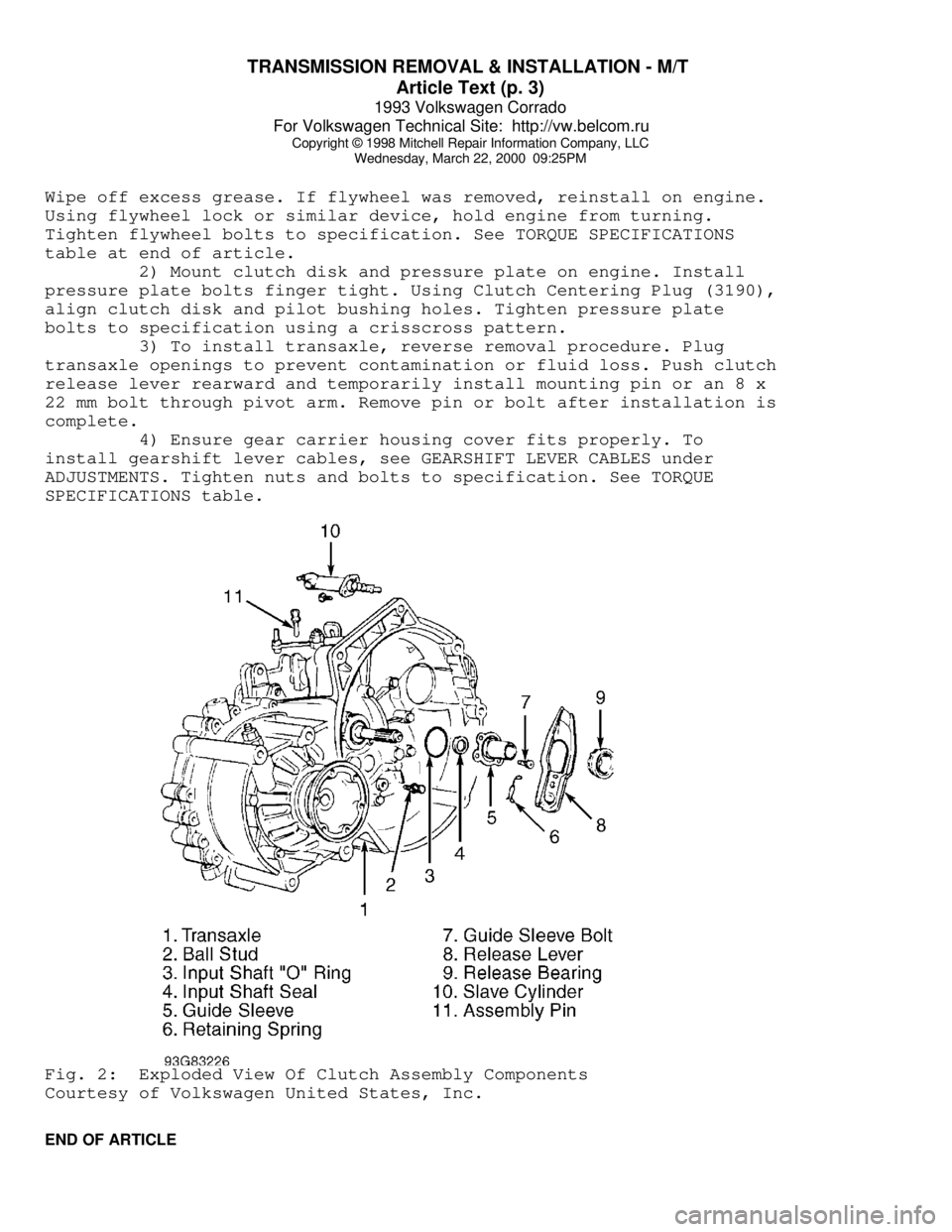
SPECIFICATIONS table.Fig. 2: Exploded View Of Clutch Assembly Components
Courtesy of Volkswagen United States, Inc.
END OF ARTICLE
Page 862 of 920

WAVEFORMS - INJECTOR PATTERN TUTORIAL
Article Text (p. 3)
1993 Volkswagen Corrado
For Volkswagen Technical Site: http://vw.belcom.ru
Copyright © 1998 Mitchell Repair Information Company, LLC
Wednesday, March 22, 2000 09:26PM
Let's move to the other situation where a noid light flashes
normally when it should be dim. This could occur if a more sensitive
noid light is used on a higher voltage/amperage circuit that was
weakened enough to cause problems (but not outright broken). A circuit
with an actual problem would thus appear normal.
Let's look at why. A noid light does not come close to
consuming as much amperage as an injector solenoid. If there is a
partial driver failure or a minor voltage drop in the injector
circuit, there can be adequate amperage to fully operate the noid
light BUT NOT ENOUGH TO OPERATE THE INJECTOR.
If this is not clear, picture a battery with a lot of
corrosion on the terminals. Say there is enough corrosion that the
starter motor will not operate; it only clicks. Now imagine turning on
the headlights (with the ignition in the RUN position). You find they
light normally and are fully bright. This is the same idea as noid
light: There is a problem, but enough amp flow exists to operate the
headlights ("noid light"), but not the starter motor ("injector").
How do you identify and avoid all these situations? By using
the correct type of noid light. This requires that you understanding
the types of injector circuits that your noid lights are designed for.
There are three. They are:
* Systems with a voltage controlled injector driver. Another
way to say it: The noid light is designed for a circuit with
a "high" resistance injector (generally 12 ohms or above).
* Systems with a current controlled injector driver. Another
way to say it: The noid light is designed for a circuit with
a low resistance injector (generally less than 12 ohms)
without an external injector resistor.
* Systems with a voltage controlled injector driver and an
external injector resistor. Another way of saying it: The
noid light is designed for a circuit with a low resistance
injector (generally less than 12 ohms) and an external
injector resistor.
NOTE: Some noid lights can meet both the second and third
categories simultaneously.
If you are not sure which type of circuit your noid light is
designed for, plug it into a known good car and check out the results.
If it flashes normally during cranking, determine the circuit type by
finding out injector resistance and if an external injector resistor
is used. You now know enough to identify the type of injector circuit.
Label the noid light appropriately.
Next time you need to use a noid light for diagnosis,
determine what type of injector circuit you are dealing with and
select the appropriate noid light.
Of course, if you suspect a no-pulse condition you could plug
in any one whose connector fit without fear of misdiagnosis. This is
because it is unimportant if the flashing light is dim or bright. It
is only important that it flashes.