1993 VOLKSWAGEN CORRADO coolant temperature
[x] Cancel search: coolant temperaturePage 116 of 920

* ENGINE SYSTEMS UNIFORM INSPECTION GUIDELINES *
Article Text (p. 19)
1993 Volkswagen Corrado
For Volkswagen Technical Site: http://vw.belcom.ru
Copyright © 1998 Mitchell Repair Information Company, LLC
Wednesday, March 22, 2000 08:41PM
POWERTRAIN CONTROL MODULE (PCM)ÄÄÄÄÄÄÄÄÄÄÄÄÄÄÄÄÄÄÄÄÄÄÂÄÄÄÄÄÄÄÄÄÄÄÄÄÄÄÄÄÄÄÄÄÄÄÄÄÄÄÄÄÄÄÄÄÄÄÄÄÄÄÄÄÄÄÄÄÄÄCondition
³ Procedure
ÄÄÄÄÄÄÄÄÄÄÄÄÄÄÄÄÄÄÄÄÄÄÅÄÄÄÄÄÄÄÄÄÄÄÄÄÄÄÄÄÄÄÄÄÄÄÄÄÄÄÄÄÄÄÄÄÄÄÄÄÄÄÄÄÄÄÄÄÄÄInoperative
³ Require repair or replacement.
ÄÄÄÄÄÄÄÄÄÄÄÄÄÄÄÄÄÄÄÄÄÄÅÄÄÄÄÄÄÄÄÄÄÄÄÄÄÄÄÄÄÄÄÄÄÄÄÄÄÄÄÄÄÄÄÄÄÄÄÄÄÄÄÄÄÄÄÄÄÄDamaged
³ Suggest repair or replacement.
ÄÄÄÄÄÄÄÄÄÄÄÄÄÄÄÄÄÄÄÄÄÄÁÄÄÄÄÄÄÄÄÄÄÄÄÄÄÄÄÄÄÄÄÄÄÄÄÄÄÄÄÄÄÄÄÄÄÄÄÄÄÄÄÄÄÄÄÄÄÄ SENSORS/ACTUATORS DEFINITIONS
NOTE: The conditions and procedures apply to, but are not limited
to the following list of components (SAE J1930 Terminology).
SENSORS/ACTUATORS DEFINITIONS
ÄÄÄÄÄÄÄÄÄÄÄÄÄÄÄÄÄÄÄÄÄÄÄÄÄÄÄÄÄÄÄÄÄÄÄÄÄÄÄÄÄÄÄÄÄÄÄÄÄÄÄÄÄÄÄÄÄÄÄÄÄÄÄÄÄÄÄÄÄÄSensor Abbreviation
02 Sensor ...................................... 02S
Intake Air Temperature Sensor .................. IAT
Manifold Absolute Pressure Sensor .............. MAP
Engine Coolant Temperature Sensor .............. ECT
Barometric Pressure Sensor ..................... BARO
Crankshaft Position Sensor ..................... CKP
Throttle Positon Sensor ........................ TPS
Camshaft Position Sensor ....................... CMP
Park Neutral Position .......................... PNP
Clutch Pedal Position Switch ................... CPP
Wide Open Throttle Switch ...................... WOT Switch
Exhaust Gas Recirculation
Valve Position Sensor ........................ EGR Valve
Position Sensor
Mass Air Flow Sensor ........................... MAF
Volume Air Flow Sensor ......................... VAF
Power Steering Pressure Sensor ................. PSP
Vehicle Speed Sensor ........................... VSS
Fan Control Sensor ............................. FS
Knock Sensor ................................... KS
Air Conditioning Cycling Switch ................ AC
Exhaust Gas Recirculating
Temperature Sensor ............................ EGRT
Transmission Range Switch ...................... TR Switch
Actuators Abbreviation
Idle Speed Control Actuator .................... ISC
Idle Air Control ............................... IAC
Exhaust Gas Recirculation Solenoid ............. EGR Solenoid
Vacuum Regulator Solenoid ...................... ...
Mix Control Solenoid ........................... MC Solenoid
Torque Converter Clutch ........................ TCC
Fuel Injector .................................. ...
Page 368 of 920

A/C SYSTEM GENERAL DIAGNOSTIC PROCEDURES
Article Text (p. 6)
1993 Volkswagen Corrado
For Volkswagen Technical Site: http://vw.belcom.ru
Copyright © 1998 Mitchell Repair Information Company, LLC
Wednesday, March 22, 2000 08:48PM
* Restricted air inlet.
* Mode doors binding.
* Blower motor inoperative.
* Temperature above system capacity.
HEATING GENERAL TROUBLE SHOOTING
CONDITION & POSSIBLE CAUSE
Insufficient, Erratic, or No Heat
* Low coolant level.
* Incorrect thermostat.
* Restricted coolant flow through heater core.
* Heater hoses plugged.
* Misadjusted control cable.
* Sticking heater control valve.
* Vacuum hose leaking.
* Vacuum hose blocked.
* Vacuum motors inoperative.
* Blocked air inlet.
* Inoperative heater blower motor.
* Oil residue on heater core fins.
* Dirt on heater core fins.
Too Much Heat
* Improperly adjusted cables.
* Sticking heater control valve.
* No vacuum to heater control valve.
* Temperature door stuck open.
Airflow Changes During Acceleration
* Vacuum system leak.
* Bad check valve or reservoir.
Air From Defroster At All Times
* Vacuum system leak.
* Improperly adjusted control cables.
* Inoperative vacuum motor.
Blower Does Not Operate Correctly
* Blown fuse.
* Blower motor windings open.
* Resistors burned out.
* Motor ground connection loose.
* Wiring harness connections loose.
* Blower motor switch inoperative.
* Blower relay inoperative.
* Fan binding or foreign object in housing.
* Fan blades broken or bent.
END OF ARTICLE
Page 379 of 920

A/C-HEATER SYSTEM - MANUAL
Article Text (p. 4)
1993 Volkswagen Corrado
For Volkswagen Technical Site: http://vw.belcom.ru
Copyright © 1998 Mitchell Repair Information Company, LLC
Wednesday, March 22, 2000 08:49PM
too low. This protects compressor if not enough refrigerant is in
system. Low-pressure cut-out switch shuts compressor off at about 29
psi (2.0 kg/cmý).
THERMOSWITCH
Thermoswitch shuts compressor off if coolant temperature is
greater than 248
øF (120øC).
ADJUSTMENTS
AIR DISTRIBUTION CONTROL
1) Move air distribution control knob to defrost position.
Connect 3-foot long control cable to footwell/defrost flap lever. Push
flap lever toward cable and secure cable sheath with retainer clip.
2) Move air distribution control knob to panel (vent)
position. Connect 2-foot long control cable to center flap lever. Push
flap lever away from cable and secure cable sheath with retainer clip.
TEMPERATURE CONTROL
Move temperature knob to full cool position. Connect
temperature control cable (Blue sheath) to temperature flap lever.
Push flap lever away from cable and secure cable sheath with retainer
clip.
TROUBLE SHOOTING
NO COOLING
1) Ensure blower fan motor operates in all 4 speeds. Ensure
air duct closes off outside air and heater water valve is closed.
Clean condenser.
2) Inspect receiver-drier pressure seal. If seal is good, go
to step 3). If seal is broken, replace seal. Evacuate and recharge
system. If system cools properly, testing is complete. If system does
not cool, connect pressure gauges.
3) Adjust engine speed to 2500 RPM. Set controls for maximum
cooling and high fan. Insert thermometer in left air duct and close
all other ducts. With vehicle in shade, close windows and doors and
connect pressure gauges. Operate system for 10 minutes.
4) If fan does not operate, replace pressure switch. Ensure
system is okay. If fan does come on, turn engine off, and check for
condenser obstructions and blocked airflow.
5) Turn air conditioner on and off with temperature control.
Ensure compressor clutch engages. Push lever to extreme right position
and back again. A click should be heard from compressor clutch. If a
click is not heard, check for voltage at clutch coil wire with switch
on. If voltage is present, replace clutch coil. If voltage is not
present, check wiring or replace thermostatic switch.
6) If compressor clutch operates, check gauge readings. If
Page 395 of 920

ABBREVIATIONS
Article Text (p. 3)
1993 Volkswagen Corrado
For Volkswagen Technical Site: http://vw.belcom.ru
Copyright © 1998 Mitchell Repair Information Company, LLC
Wednesday, March 22, 2000 08:49PM³CBD ³Closed Bowl Distributor ³
³CBVV
³Carburetor Bowl Vent Valve ³
³cc
³Cubic Centimeter ³
³CCC
³Computer Command Control ³
³CCD
³Computer Controlled Dwell ³
³CCM
³Central Control Module ³
³CCO
³Converter Clutch Override ³
³CCOT
³Cycling Clutch Orifice Tube ³
³CCW
³Counterclockwise ³
³CDI
³Capacitor Discharge Ignition ³
³CEC
³Computerized Engine Control ³
³CFI
³Central Fuel Injection ³
³CID
³Cubic Inch Displacement ³
³CID
³Cylinder Identification sensor ³
³CIS
³Continuous Injection System ³
³CIS-E
³Continuous Injection System-Electronic ³
³CKT
³Circuit ³
³CLR
³Clear ³
³CNG
³Compressed Natural Gas ³
³CO
³Carbon Monoxide ³
³CO2
³Carbon Dioxide ³
³CONV
³Convertible ³
³CP
³Canister Purge ³
³CPA
³Connector Position Assurance ³
³CPS
³Crank Position Sensor ³
³CTS
³Coolant Temperature Sensor ³
³CV
³Check Valve or Constant Velocity ³
³CVC
³Constant Vacuum Control ³
³CW
³Clockwise ³
³CYL or Cyl.
³Cylinder ³
³Calif.
³California ³
³Carb.
³Carburetor ³
³Chrg.
³Charging ³
³Circ.
³Circuit ³
³Cntrl.
³Control ³
³Comp.
³Compressor or Compartment ³
³Conn.
³Connector ³
³Cont.
³Continued ³
³Conv.
³Convertible or Converter ³
³Cu. In.
³Cubic Inch ³
³Cyl.
³Cylinder ³
ÀÄÄÄÄÄÄÄÄÄÄÄÄÄÄÄÄÄÁÄÄÄÄÄÄÄÄÄÄÄÄÄÄÄÄÄÄÄÄÄÄÄÄÄÄÄÄÄÄÄÄÄÄÄÄÄÄÄÄÄÄÄÄÄÄÄÄÄÄÙ "D" ABBREVIATION TABLE
"D" ABBREVIATION TABLE
ÚÄÄÄÄÄÄÄÄÄÄÄÄÄÄÄÄÄÂÄÄÄÄÄÄÄÄÄÄÄÄÄÄÄÄÄÄÄÄÄÄÄÄÄÄÄÄÄÄÄÄÄÄÄÄÄÄÄÄÄÄÄÄÄÄÄÄÄÄ¿
³ABBREVIATION
³DEFINITION ³
ÃÄÄÄÄÄÄÄÄÄÄÄÄÄÄÄÄÄÅÄÄÄÄÄÄÄÄÄÄÄÄÄÄÄÄÄÄÄÄÄÄÄÄÄÄÄÄÄÄÄÄÄÄÄÄÄÄÄÄÄÄÄÄÄÄÄÄÄÄ´
³"D"
³Drive ³
³DBC
³Dual Bed Catalyst ³
³DC
³Direct Current or Discharge ³
Page 396 of 920

ABBREVIATIONS
Article Text (p. 4)
1993 Volkswagen Corrado
For Volkswagen Technical Site: http://vw.belcom.ru
Copyright © 1998 Mitchell Repair Information Company, LLC
Wednesday, March 22, 2000 08:49PM³DDD ³Dual Diaphragm Distributor ³
³DERM
³Diagnostic Energy Reserve Module ³
³DFI
³Digital Fuel Injection ³
³DIC
³Driver Information Center ³
³DIS
³Direct Ignition System ³
³DIS
³Distributorless Ignition System ³
³DIST
³Distribution ³
³DISTR
³Distributor ³
³DK BLU
³Dark Blue ³
³DK GRN
³Dark Green ³
³DME
³Digital Motor Electronics (Motronic System) ³
³DOHC
³Double Overhead Cam ³
³DOT
³Department of Transportation ³
³DP
³Dashpot ³
³DRB-II
³Diagnostic Readout Box ³
³DVOM
³Digital Volt/Ohm Meter (see VOM) ³
³Def.
³Defogger or Defroster ³
³Def.
³Defrost ³
³Defog.
³Defogger ³
³Diag.
³Diagnostic ³
³Dist.
³Distributor or Distribution ³
³Dr.
³Door ³
ÀÄÄÄÄÄÄÄÄÄÄÄÄÄÄÄÄÄÁÄÄÄÄÄÄÄÄÄÄÄÄÄÄÄÄÄÄÄÄÄÄÄÄÄÄÄÄÄÄÄÄÄÄÄÄÄÄÄÄÄÄÄÄÄÄÄÄÄÄÙ "E" ABBREVIATION TABLE
"E" ABBREVIATION TABLE
ÚÄÄÄÄÄÄÄÄÄÄÄÄÄÄÄÄÄÂÄÄÄÄÄÄÄÄÄÄÄÄÄÄÄÄÄÄÄÄÄÄÄÄÄÄÄÄÄÄÄÄÄÄÄÄÄÄÄÄÄÄÄÄÄÄÄÄÄÄ¿
³ABBREVIATION
³DEFINITION ³
ÃÄÄÄÄÄÄÄÄÄÄÄÄÄÄÄÄÄÅÄÄÄÄÄÄÄÄÄÄÄÄÄÄÄÄÄÄÄÄÄÄÄÄÄÄÄÄÄÄÄÄÄÄÄÄÄÄÄÄÄÄÄÄÄÄÄÄÄÄ´
³EAC
³Electric Assist Choke ³
³EACV
³Electric Air Control Valve ³
³EBCM
³Electronic Brake Control Module ³
³ECA
³Electronic Control Assembly ³
³ECAT
³Electronically Controlled Automatic Transaxle ³
³ECM
³Electronic Control Module ³
³ECT
³Engine Coolant Temperature Sensor ³
³ECU
³Electronic Control Unit or Engine Control Unit ³
³EDF
³Electric Drive Fan relay assembly ³
³EDIS
³Electronic Distributorless Ignition System ³
³EEC
³Electronic Engine Control ³
³EECS
³Evaporative Emission Control System ³
³EEPROM
³Electronically Erasable PROM ³
³EFE
³Early Fuel Evaporation ³
³EFI
³Electronic Fuel Injection ³
³EGO
³Exhaust Gas Oxygen sensor (see HEGO) ³
³EGR
³Exhaust Gas Recirculation system ³
³EGRC
³EGR Control solenoid or system ³
³EGRV
³EGR Vent solenoid or system ³
³EMR
³Emission Maintenance Reminder Module ³
³ESA
³Electronic Spark Advance ³
³ESC
³Electronic Spark Control ³
Page 480 of 920

ELECTRICAL COMPONENT LOCATOR
Article Text (p. 22)
1993 Volkswagen Corrado
For Volkswagen Technical Site: http://vw.belcom.ru
Copyright © 1998 Mitchell Repair Information Company, LLC
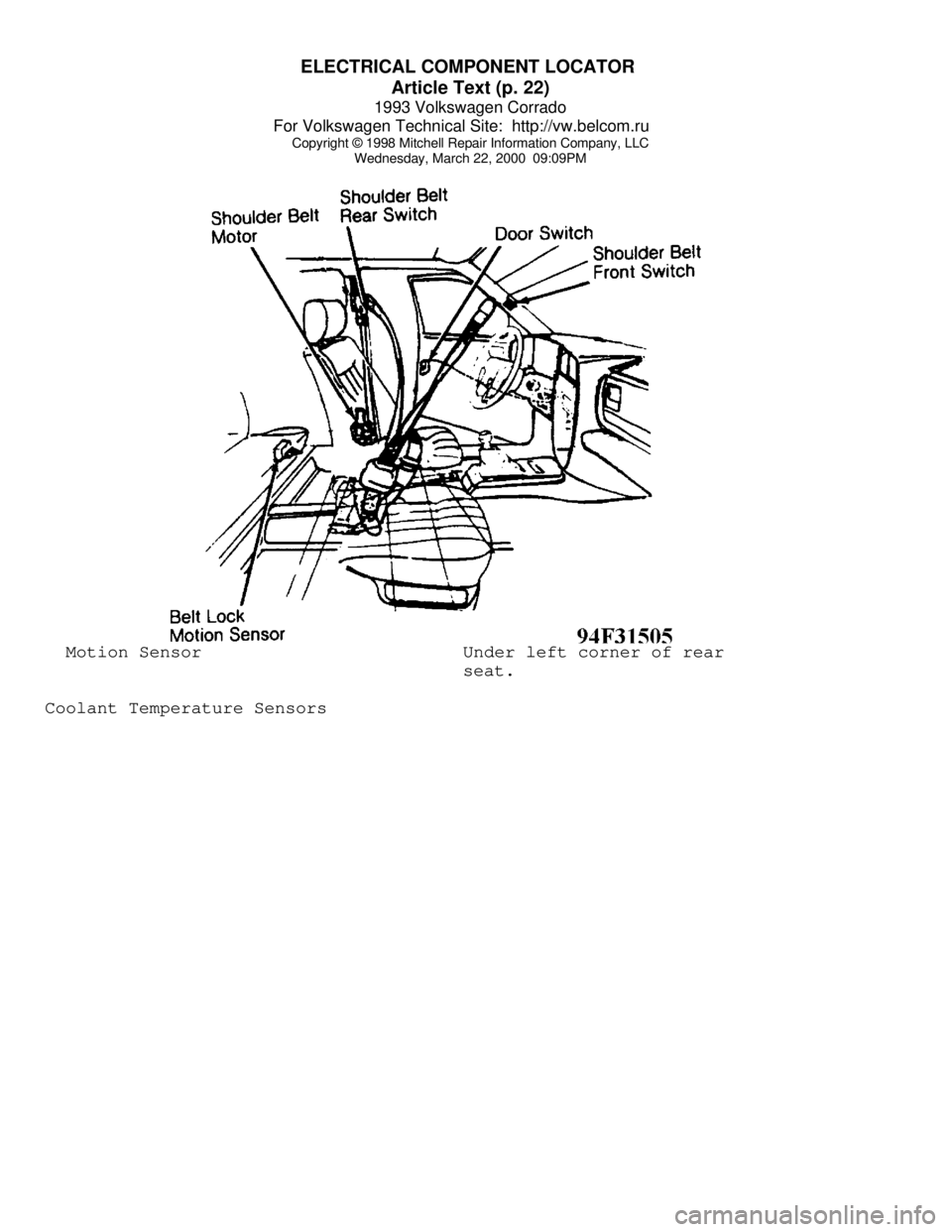
Wednesday, March 22, 2000 09:09PM Motion Sensor Under left corner of rear
seat.
Coolant Temperature Sensors
Page 483 of 920

ELECTRICAL COMPONENT LOCATOR
Article Text (p. 25)
1993 Volkswagen Corrado
For Volkswagen Technical Site: http://vw.belcom.ru
Copyright © 1998 Mitchell Repair Information Company, LLC
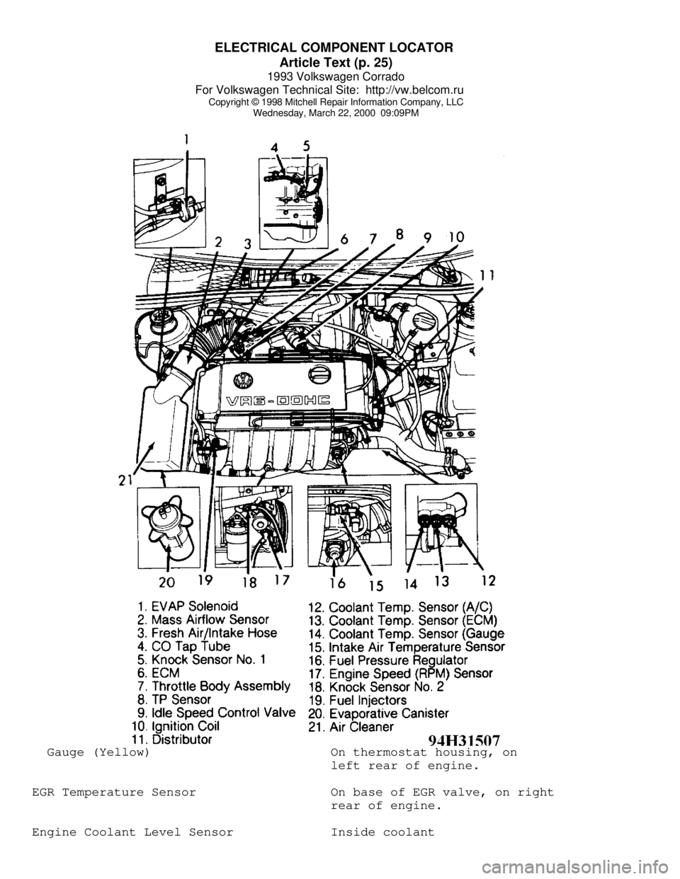
Wednesday, March 22, 2000 09:09PM Gauge (Yellow) On thermostat housing, on
left rear of engine.
EGR Temperature Sensor On base of EGR valve, on right
rear of engine.
Engine Coolant Level Sensor Inside coolant
Page 506 of 920

E - THEORY/OPERATION
Article Text
1993 Volkswagen Corrado
For Volkswagen Technical Site: http://vw.belcom.ru
Copyright © 1998 Mitchell Repair Information Company, LLC
Wednesday, March 22, 2000 09:09PM
ARTICLE BEGINNING
1993 ENGINE PERFORMANCE
Volkswagen Theory & Operation - Motronic
Corrado SLC
INTRODUCTION
This article covers basic description and operation of engine
performance-related systems and components. Read this article before
diagnosing vehicles or systems with which you are not completely
familiar.
COMPUTERIZED ENGINE CONTROLS
ELECTRONIC CONTROL UNIT
The Motronic engine management system uses a single
Electronic Control Module (ECM) for fuel injection, idle speed
control, ignition, and emission controls. The Electronic Control
Module (ECM) continually corrects air/fuel mixture based on signals
from various signals. The ECM is located underneath center of
windshield cowl, directly behind engine compartment firewall.
NOTE: Components are grouped into 2 categories. The first category
covers INPUT DEVICES, which control or produce voltage
signals monitored by the control unit. The second category
covers OUTPUT SIGNALS, which are components controlled by
the control unit.
INPUT DEVICES
Engine Coolant Temperature (ECT) Sensor
Sensor is located on thermostat housing. As engine coolant
temperature increases, the resistance of the sensor decreases. Engine
coolant temperature sensor signals are used for control of ignition
timing, injector pulse width, and idle speed stabilization. In
addition, knock sensors, idle speed control, oxygen sensor and fuel
tank venting are activated based on coolant temperature.
Engine Speed (RPM)/Reference Sensor
Engine speed (RPM) and crankshaft position are registered by
a single sensor located on side of engine block. The sensor reads a
toothed wheel mounted on the crankshaft. The wheel has a 2-tooth gap
which is used as a reference point for crankshaft position. The engine
speed/reference signal is used to monitor engine RPM and to identify
TDC position of cylinder No. 1.
Hall Effect Sensor
See ELECTRONIC IGNITION SYSTEM under IGNITION SYSTEM in this