1993 VOLKSWAGEN CORRADO coolant
[x] Cancel search: coolantPage 595 of 920

GENERAL COOLING SYSTEM SERVICING
Article Text (p. 2)
1993 Volkswagen Corrado
For Volkswagen Technical Site: http://vw.belcom.ru
Copyright © 1998 Mitchell Repair Information Company, LLC
Wednesday, March 22, 2000 09:11PM
To flush engine, remove thermostat and replace housing.
Connect flushing gun to water outlet of engine. Flush using short air
bursts until water runs clean.
Heater Core
Flush heater core as described for radiator. Ensure heater
control valve is set to maximum heat position before flushing heater.
REFILLING
To prevent air from being trapped in engine block, engine
should be running when refilling cooling system. After system is full,
continue running engine until thermostat is open, then recheck fill
level. Do not overfill system.
TESTING
THERMOSTAT
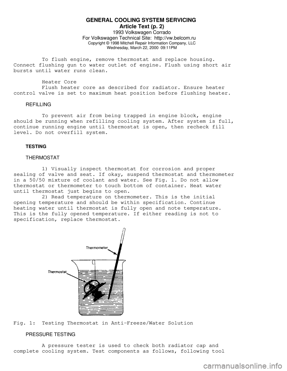
1) Visually inspect thermostat for corrosion and proper
sealing of valve and seat. If okay, suspend thermostat and thermometer
in a 50/50 mixture of coolant and water. See Fig. 1. Do not allow
thermostat or thermometer to touch bottom of container. Heat water
until thermostat just begins to open.
2) Read temperature on thermometer. This is the initial
opening temperature and should be within specification. Continue
heating water until thermostat is fully open and note temperature.
This is the fully opened temperature. If either reading is not to
specification, replace thermostat.Fig. 1: Testing Thermostat in Anti-Freeze/Water Solution
PRESSURE TESTING
A pressure tester is used to check both radiator cap and
complete cooling system. Test components as follows, following tool
Page 599 of 920

H - TESTS W/O CODES
Article Text (p. 3)
1993 Volkswagen Corrado
For Volkswagen Technical Site: http://vw.belcom.ru
Copyright © 1998 Mitchell Repair Information Company, LLC
Wednesday, March 22, 2000 09:11PM
NOTE: Symptoms listed are for CIS-E Motronic system. When working
on Digifant and Motronic systems, use symptoms listed only
as a diagnostic guide. A list of specific symptoms for
Digifant and Motronic systems is not available from
manufacturer.
ENGINE DOES NOT START OR IS DIFFICULT TO START WHEN COLD
* Check for insufficient fuel in tank.
* Check fuel pump relay and fuel pump.
* Check fuel system for leaks.
* Check auxiliary air intake system.
* Check fuel system after-start, acceleration enrichment and
warm-up circuits.
* Check cold-start valve.
* Check airflow sensor lever adjustment and control plunger.
* Check sensor plate rest position and idle circuit.
* Check fuel system differential and residual pressures.
* Check fuel injection volume.
* Check engine coolant temperature sensor.
* Check ignition timing, spark plugs, distributor, secondary
ignition wiring and coil.
* Check Hall Effect sensor.
* Check ignition coil power output stage.
ENGINE DOES NOT START OR IS DIFFICULT TO START WHEN WARM
* Check radiator cooling fan after-run circuit.
* Check fuel pump check valve.
* Check fuel evaporative frequency solenoid(s).
* Check fuel system for leaks.
* Check auxiliary air intake system.
* Check idle speed.
* Check fuel system after-start, acceleration enrichment and
warm-up circuits.
* Check cold-start valve.
* Check injector fuel pressure and volume.
* Check sensor plate rest position and idle circuit.
* Check sealing ring under control plunger.
* Check fuel system differential and residual pressures.
* Check engine coolant temperature sensor.
* Check ignition timing, spark plugs, distributor, secondary
ignition wiring and coil.
UNEVEN IDLE OR NO IDLE WITH COLD ENGINE OR DURING WARM-UP
* Check fuel evaporative frequency solenoid(s).
* Check fuel system for leaks.
* Check auxiliary air intake system.
* Check idle speed.
* Check oxygen sensor control circuit.
Page 600 of 920

H - TESTS W/O CODES
Article Text (p. 4)
1993 Volkswagen Corrado
For Volkswagen Technical Site: http://vw.belcom.ru
Copyright © 1998 Mitchell Repair Information Company, LLC
Wednesday, March 22, 2000 09:11PM
* Check cold-start valve.
* Check injector fuel pressure and volume.
* Check throttle potentiometer.
* Check fuel system differential and residual pressures.
* Check idle switch.
* Check engine coolant temperature sensor.
* Check exhaust system.
* Check ignition timing and spark plugs.
ENGINE STARTS BUT STALLS
* Check fuel pump relay and fuel pump.
* Check auxiliary air intake system.
* Check idle speed.
* Check fuel system after-start, acceleration enrichment and
warm-up circuits.
* Check airflow sensor lever adjustment and control plunger.
* Check sensor plate rest position and idle circuit.
* Check fuel system differential and residual pressures.
* Check idle switch.
* Check engine coolant temperature sensor.
IDLE SPEED EXCEEDS SPECIFICATION
* Check throttle cable adjustment.
* Check fuel evaporative frequency solenoid(s).
* Check auxiliary air intake system.
* Check idle speed.
* Check throttle potentiometer.
* Check idle switch.
* Check engine coolant temperature sensor.
* Check throttle body basic adjustment.
* Check ignition timing.
POOR ACCELERATION WITH COLD ENGINE OR DURING WARM-UP
* Check fuel pump.
* Check auxiliary air intake system.
* Check oxygen sensor control circuit.
* Check fuel system after-start, acceleration enrichment and
warm-up circuits.
* Check airflow sensor lever adjustment and control plunger.
* Check throttle potentiometer.
* Check fuel system differential and residual pressures.
* Check injector fuel pressure and volume.
* Check idle switch.
* Check engine coolant temperature sensor.
* Check throttle body basic adjustment.
* Check exhaust system.
* Check ignition timing, spark plugs, distributor, secondary
ignition wiring and coil.
Page 608 of 920

HOW TO USE SYSTEM WIRING DIAGRAMS
Article Text (p. 5)
1993 Volkswagen Corrado
For Volkswagen Technical Site: http://vw.belcom.ru
Copyright © 1998 Mitchell Repair Information Company, LLC
Wednesday, March 22, 2000 09:11PM
Body Control Module .......................... Body Control Computer
Anti-Theft System
Daytime Running Lights
Engine Performance
Headlight Systems
Warning Systems
Boost Control Solenoid .......................... Engine Performance
Boost Sensor .................................... Engine Performance
Brake Fluid Level Switch .................. Analog Instrument Panels
Brake On/Off (BOO) Switch ................... Cruise Control Systems
Engine Performance
Shift Interlock Systems
Buzzer Module ...................................... Warning Systems
Camshaft Position (CMP) Sensor .................. Engine Performance
Central Control Module ........................... Anti-Theft System
Clockspring ............................... Air Bag Restraint System
Cruise Control Systems
Steering Column Switches
Clutch Pedal Position Switch .............................. Starters
Clutch Start Switch ....................................... Starters
Combination Meter ......................... Analog Instrument Panels
Constant Control Relay Module (CCRM) ............ Engine Performance
Electric Cooling Fans
Convenience Center .............................. Power Distribution
Illumination/Interior Lights
Convertible Top Motor ........................ Power Convertible Top
Convertible Top Switch ....................... Power Convertible Top
Crankshaft Position (CKP) Sensor ................ Engine Performance
Cruise Control Module ....................... Cruise Control Systems
Cruise Control Switch ....................... Cruise Control Systems
Condenser Fan Relay(s) ....................... Electric Cooling Fans
Data Link Connector (DLC) ....................... Engine Performance
Daytime Running Lights Module ............... Daytime Running Lights
Exterior Lights
Defogger Relay ................................ Rear Window Defogger
Diagnostic Energy Reserve Module (DERM) ... Air Bag Restraint System
Discriminating Sensor (Air Bag) ........... Air Bag Restraint System
Distributor ..................................... Engine Performance
Door Lock Actuators ............................... Power Door Locks
Remote Keyless Entry
Door Lock Relay(s) ................................ Power Door Locks
Electrochromic Mirror ................................ Power Mirrors
Electronic Level Control (ELC)
Height Sensor .............................. Electronic Suspension
Electronic Level Control (ELC) Module ........ Electronic Suspension
Engine Coolant Temperature (ECT)
Sending Unit ............................ Analog Instrument Panels
Engine Coolant Temperature (ECT) Sensor ......... Engine Performance
Engine Control Module ........................... Engine Performance
Generators & Regulators
Starters
ETACS ECU .......................................... Warning Systems
Page 614 of 920

I - SYSTEM/COMPONENT TESTS
Article Text (p. 2)
1993 Volkswagen Corrado
For Volkswagen Technical Site: http://vw.belcom.ru
Copyright © 1998 Mitchell Repair Information Company, LLC
Wednesday, March 22, 2000 09:11PM
COMPUTERIZED ENGINE CONTROLS
ELECTRONIC CONTROL MODULE (ECM)
Ground & Power Circuits
Check ECM ground and power circuits using the values in the
appropriate J - PIN VOLTAGE CHARTS article.
ENGINE SENSORS & SWITCHES
ENGINE COOLANT TEMPERATURE SENSOR
Corrado SLC (2.8L)
1) Ensure engine is cold. Connect Scan Tester (VAG 1551) to
Data Link Connectors (DLC) located in center console, in front of
shift lever. Start engine and allow it to idle.
2) With scan tester in READ TEST VALUE BLOCK function, select
group No. 01 and read coolant temperature value in field No. 2 of scan
tester. Temperature value must increase uniformly without
interruption. If value increases as specified, select END OUTPUT
function on scan tester.
3) If displayed value does not change or if engine
malfunctions during certain temperature ranges, turn ignition off and
measure engine coolant temperature sensor resistance. See ENGINE
COOLANT TEMPERATURE SENSOR RESISTANCE table.
ENGINE COOLANT TEMPERATURE SENSOR RESISTANCEÄÄÄÄÄÄÄÄÄÄÄÄÄÄÄÄÄÄÄÄÄÄÄÄÄÄÄÄÄÄÄÄÄÄÄÄÄÄÄÄÄÄÄÄÄTemperature
øF (øC) Ohms
68 (20) ......................... 3000-2000
86 (30) ......................... 2000-1500
104 (40) ........................ 1500-1000
122 (50) ......................... 1000-800
140 (60) .......................... 700-500
158 (70) .......................... 500-375
176 (80) .......................... 375-275
194 (90) .......................... 275-225
ÄÄÄÄÄÄÄÄÄÄÄÄÄÄÄÄÄÄÄÄÄÄÄÄÄÄÄÄÄÄÄÄÄÄÄÄÄÄÄÄÄÄÄÄÄ INTAKE AIR TEMPERATURE SENSOR
Corrado SLC (2.8L)
1) Turn ignition off. Disconnect intake air temperature
sensor. Remove sensor from intake manifold and plug opening in
manifold. Reconnect sensor to wiring harness.
2) Connect Scan Tester (VAG 1551) to Data Link Connectors
(DLC) located in center console, in front of shift lever. Start engine
and allow it to idle. With scan tester in READ TEST VALUE BLOCK
function, select group 03 and read intake air temperature sensor value
in field No. 4 of scan tester.
3) Spray sensor with cooling spray and observe value on scan
Page 615 of 920

I - SYSTEM/COMPONENT TESTS
Article Text (p. 3)
1993 Volkswagen Corrado
For Volkswagen Technical Site: http://vw.belcom.ru
Copyright © 1998 Mitchell Repair Information Company, LLC
Wednesday, March 22, 2000 09:11PM
tester. Scan tester value must decrease. If temperature value does not
change, repair intake air temperature sensor circuit or replace sensor
as necessary. After repairs, erase Diagnostic Trouble Code (DTC)
memory (if applicable) and select END OUTPUT function.
HALL EFFECT SENSOR
Corrado SLC (2.8L)
Testing information is not available from manufacturer. These
vehicles are equipped with a distributorless ignition system.
FUEL SYSTEM
ACCELERATION/FULL THROTTLE ENRICHMENT & DECELERATION FUEL
CUT-OFF
Corrado SLC (2.8L)
1) Ensure engine coolant temperature is at least 176øF
(80
øC). Connect Scan Tester (VAG 1551) to Data Link Connectors (DLC)
located in center console, in front of shift lever.
2) Start engine and allow it to idle. With scan tester in
READ TEST VALUE BLOCK function, select group No. 04 and read value in
field No. 4 of scan tester. Display value must be 00010 at idle.
3) Using accelerator pedal, increase engine speed to 3000 RPM
and observe scan tester. Display value in field No. 4 of scan tester
must briefly be 10100. Release accelerator pedal and observe scan
tester.
4) Display value in field No. 4 of scan tester must briefly
be 00011, then return to 00010 at idle. If values are not as
specified, see THROTTLE POSITION (TP) SENSOR ADJUSTMENT procedures in
the D - ADJUSTMENTS article. If values are as specified, select END
OUTPUT function on scan tester.
FUEL INJECTORS & CIRCUIT
Corrado SLC (2.8L)
1) To access fuel injectors, remove ignition wires. Remove
hose from mass airflow sensor. Disconnect hose to fuel evaporative
(frequency) solenoid valve at throttle body.
2) Disconnect throttle position sensor and idle air control
valve. Disconnect accelerator cable from throttle body. Disconnect and
plug coolant hoses at throttle body.
3) Disconnect hose from air intake heated tube. Detach fuel
lines at cylinder head cover and remove from fuel rail. Disconnect
vacuum hose from fuel pressure regulator. Remove intake manifold upper
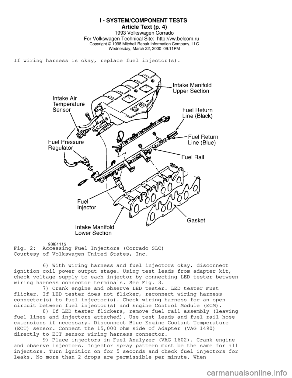
section. See Fig. 2.
4) With intake manifold upper section removed, disconnect
wiring harness from fuel injectors. Using a Digital Volt-Ohmmeter
(DVOM) and test leads from Adapter Kit (VW 1594), check fuel injector
resistance. See Fig. 3.
5) Fuel injector resistance should be 15.0-21.5 ohms. If
resistance is zero ohms, check for a short circuit in wiring harness.
Page 616 of 920

I - SYSTEM/COMPONENT TESTS
Article Text (p. 4)
1993 Volkswagen Corrado
For Volkswagen Technical Site: http://vw.belcom.ru
Copyright © 1998 Mitchell Repair Information Company, LLC
Wednesday, March 22, 2000 09:11PM
If wiring harness is okay, replace fuel injector(s).Fig. 2: Accessing Fuel Injectors (Corrado SLC)
Courtesy of Volkswagen United States, Inc.
6) With wiring harness and fuel injectors okay, disconnect
ignition coil power output stage. Using test leads from adapter kit,
check voltage supply to each injector by connecting LED tester between
wiring harness connector terminals. See Fig. 3.
7) Crank engine and observe LED tester. LED tester must
flicker. If LED tester does not flicker, reconnect wiring harness
connector(s) to fuel injector(s). Check wiring harness for an open
circuit between fuel injector(s) and Engine Control Module (ECM).
8) If LED tester flickers, remove fuel rail assembly (leaving
fuel lines and injectors attached). Use test leads and fuel rail hose
extensions if necessary. Disconnect Blue Engine Coolant Temperature
(ECT) sensor. Connect the 15,000 ohm side of Adapter (VAG 1490)
directly to ECT sensor wiring harness connector.
9) Place injectors in Fuel Analyzer (VAG 1602). Crank engine
and observe injectors. Injector spray pattern must be the same for all
injectors. Turn ignition on for 5 seconds and check fuel injectors for
leaks. No more than 2 drops are permissible per minute. When
Page 618 of 920

I - SYSTEM/COMPONENT TESTS
Article Text (p. 6)
1993 Volkswagen Corrado
For Volkswagen Technical Site: http://vw.belcom.ru
Copyright © 1998 Mitchell Repair Information Company, LLC
Wednesday, March 22, 2000 09:11PM
IGNITION COIL
EMISSION SYSTEMS & SUB-SYSTEMS
NOTE: Other than EGR system, additional emission systems and
sub-system component testing information is not available
from manufacturer.
EXHAUST GAS RECIRCULATION (EGR)
Corrado SLC (2.8L)
1) Ensure engine coolant temperature is at least 122øF
(50
øC). Start engine and allow it to idle. Disconnect vacuum hose from
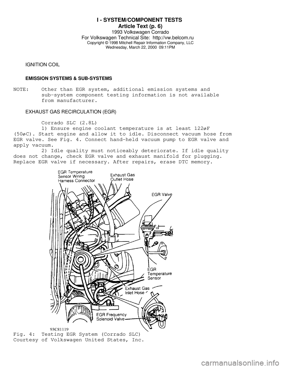
EGR valve. See Fig. 4. Connect hand-held vacuum pump to EGR valve and
apply vacuum.
2) Idle quality must noticeably deteriorate. If idle quality
does not change, check EGR valve and exhaust manifold for plugging.
Replace EGR valve if necessary. After repairs, erase DTC memory.Fig. 4: Testing EGR System (Corrado SLC)
Courtesy of Volkswagen United States, Inc.