1993 VOLKSWAGEN CORRADO fuel pressure
[x] Cancel search: fuel pressurePage 433 of 920

BRAKE SYSTEM
Article Text (p. 2)
1993 Volkswagen Corrado
For Volkswagen Technical Site: http://vw.belcom.ru
Copyright © 1998 Mitchell Repair Information Company, LLC
Wednesday, March 22, 2000 08:57PM
3) Submerge other end of hose in clean glass jar partially
filled with clean brake fluid. Pump brake pedal several times, then
hold down. Open bleeder valve. Holding pedal down, close bleeder
valve. Release brake pedal.
4) Repeat procedure until brake fluid shows no signs of air
bubbles. When bleeding rear brakes, push lever of pressure regulator
in direction of rear axle.
5) After bleeding ABS vehicles, turn ignition on. Allow pump
to run until it shuts off. If pump runs longer than 2 minutes, allow
pump to cool for 10 minutes. On all vehicles, ensure master cylinder
reservoir is full.
ADJUSTMENTS
BRAKE PRESSURE REGULATOR
CAUTION: DO NOT adjust pressure regulator with brake pedal depressed.
1) Depress brake pedal once firmly. Release brake pedal
quickly, watching for regulator lever to move when pedal is released.
If regulator lever does not move when pedal is released, replace
regulator. If regulator lever moved, go to next step.
2) Ensure vehicle fuel tank is full, luggage compartment is
empty and a driver is in driver seat. Raise and support vehicle. Using
Pressure Gauges (US 1016), attach one gauge to right rear brake
cylinder or caliper. If vehicle is ABS-equipped, go to next step. If
vehicle is not ABS-equipped, go to step 4).
3) Using Distributor "T" (803 611 755) and an additional 8"
(203 mm) of brakeline, connect one gauge in front of pressure
regulator. Bleed pressure gauge and hoses through valve on gauges.
Lower vehicle. Bounce rear of vehicle several times. Go to step 5).
4) Attach Pressure Gauges (US 1016) to left front brake
caliper. Bleed pressure gauge and hoses through valve on gauges. Lower
vehicle. Bounce rear of vehicle several times.
5) Pump brake pedal several times. Press on brake pedal until
reading on front gauge shows pressure given for first reading in the
BRAKE PRESSURES table. Hold brake pressure to specification. Rear
gauge reading should be within specification given for first reading
in the BRAKE PRESSURES table.
6) Increase pressure on brake pedal until reading on front
gauge shows pressure given for second reading in the BRAKE PRESSURES
table. Hold brake pressure to specification. Rear gauge reading should
be within specification given for second reading in BRAKE PRESSURES
table. If pressures are within specification, brake pressure regulator
is functioning properly. If pressures are not within specification, go
to next step.
7) If pressure is too high, decrease spring pressure on
regulator. If pressure is too low, increase spring pressure on
regulator. If adjusting spring pressure on regulator does not bring
pressures within specification, replace pressure regulator. Disconnect
gauges, and bleed brakes.
Page 442 of 920

C - SPECIFICATIONS
Article Text (p. 2)
1993 Volkswagen Corrado
For Volkswagen Technical Site: http://vw.belcom.ru
Copyright © 1998 Mitchell Repair Information Company, LLC
Wednesday, March 22, 2000 08:58PM
Spark Plugs .................................. 30,000
(1) - Discard mini-fuel filter at 1000-mile maintenance
interval. Install new copper gaskets.ÄÄÄÄÄÄÄÄÄÄÄÄÄÄÄÄÄÄÄÄÄÄÄÄÄÄÄÄÄÄÄÄÄÄÄÄÄÄÄÄÄÄÄÄÄÄÄÄÄÄÄÄÄÄÄBELT ADJUSTMENT
ÄÄÄÄÄÄÄÄÄÄÄÄÄÄÄÄÄÄÄÄÄÄÄÄÄÄÄÄÄÄÄÄÄÄÄÄÄÄÄÄÄÄÄÄÄÄÄÄÄÄÄÄÄÄÄApplication Specification
Serpentine Belt ................................. (1)
(1) - Serpentine belt tension is automatically adjusted
by the tensioner.
ÄÄÄÄÄÄÄÄÄÄÄÄÄÄÄÄÄÄÄÄÄÄÄÄÄÄÄÄÄÄÄÄÄÄÄÄÄÄÄÄÄÄÄÄÄÄÄÄÄÄÄÄÄÄÄ MECHANICAL CHECKS
ENGINE COMPRESSION
COMPRESSION SPECIFICATIONS
ÄÄÄÄÄÄÄÄÄÄÄÄÄÄÄÄÄÄÄÄÄÄÄÄÄÄÄÄÄÄÄÄÄÄÄÄÄÄÄÄÄÄÄÄÄÄÄÄÄÄÄÄÄÄÄApplication Specification
Compression Ratio ............................ 10.0:1
Compression
Pressure ........... 157-186 psi (11.0-13.0 kg/cm
ý)
Minimum Compression Pressure ... 106 psi (7.5 kg/cm
ý)
Maximum Variation
Between Cylinders ............. 43 psi (3.0 kg/cm
ý)
ÄÄÄÄÄÄÄÄÄÄÄÄÄÄÄÄÄÄÄÄÄÄÄÄÄÄÄÄÄÄÄÄÄÄÄÄÄÄÄÄÄÄÄÄÄÄÄÄÄÄÄÄÄÄÄ VALVE CLEARANCE
NOTE: All models are equipped with hydraulic lifters. No
adjustments are required.
IGNITION SYSTEM
IGNITION COIL
IGNITION COIL RESISTANCE - Ohms @ 68
øF (20øC)
ÄÄÄÄÄÄÄÄÄÄÄÄÄÄÄÄÄÄÄÄÄÄÄÄÄÄÄÄÄÄÄÄÄÄÄÄÄÄÄÄÄÄÄÄÄÄÄÄÄÄÄÄÄÄÄApplication Primary Secondary
Corrado SLC (1) ........ ..... .............. .....
(1) - Ignition coil pack, new for 1993, is located on
left side of cylinder head. When ignition coil is
triggered, spark is supplied to 2 spark plugs at
one time. One spark plug fires during compression
stroke and the other plug fires during exhaust
Page 444 of 920

C - SPECIFICATIONS
Article Text (p. 4)
1993 Volkswagen Corrado
For Volkswagen Technical Site: http://vw.belcom.ru
Copyright © 1998 Mitchell Repair Information Company, LLC
Wednesday, March 22, 2000 08:58PM
IGNITION TIMING
NOTE: Always refer to underhood label for latest specifications.
IGNITION TIMING (Degrees BTDC @ RPM)ÄÄÄÄÄÄÄÄÄÄÄÄÄÄÄÄÄÄÄÄÄÄÄÄÄÄÄÄÄÄÄÄÄÄÄÄÄÄÄÄÄÄÄÄÄÄÄÄÄÄÄÄÄÄÄApplication Checking Adjusting
Corrado SLC ............... (1) ............... (1)
(1) - Ignition timing is computer controlled.
Information is not available from manufacturer.
ÄÄÄÄÄÄÄÄÄÄÄÄÄÄÄÄÄÄÄÄÄÄÄÄÄÄÄÄÄÄÄÄÄÄÄÄÄÄÄÄÄÄÄÄÄÄÄÄÄÄÄÄÄÄÄIGNITION TIMING ADVANCE (Degrees BTDC @ RPM)
ÄÄÄÄÄÄÄÄÄÄÄÄÄÄÄÄÄÄÄÄÄÄÄÄÄÄÄÄÄÄÄÄÄÄÄÄÄÄÄÄÄÄÄÄÄÄÄÄÄÄÄÄÄÄÄApplication Specification
Corrado SLC ..................................... (1)
(1) - Ignition timing advance is computer controlled.
Information is not available from manufacturer.
ÄÄÄÄÄÄÄÄÄÄÄÄÄÄÄÄÄÄÄÄÄÄÄÄÄÄÄÄÄÄÄÄÄÄÄÄÄÄÄÄÄÄÄÄÄÄÄÄÄÄÄÄÄÄÄ FUEL SYSTEM
FUEL PUMP
NOTE: Fuel pump performance measures fuel pressure and volume
availability, not regulated fuel pressure.
FUEL PUMP PERFORMANCE
ÄÄÄÄÄÄÄÄÄÄÄÄÄÄÄÄÄÄÄÄÄÄÄÄÄÄÄÄÄÄÄÄÄÄÄÄÄÄÄÄÄÄÄÄÄÄÄÄÄÄÄÄÄÄÄÄÄÄÄÄÄÄÄÄÄ Pressure Min. Vol. In 30 Sec.
Application psi (kg/cm(
ý) Pts. (L)
Corrado SLC (1) .......... 58 (4.0) ....... 1.0-1.4 (0.5-0.7)
(1) - Using Adapter Cable (VAG 1348/3-2) between battery positive
terminal and terminal No. 4 of fuel pump relay socket. Fuel
pump energized, with 10-12 volts at fuel pump and engine off.
ÄÄÄÄÄÄÄÄÄÄÄÄÄÄÄÄÄÄÄÄÄÄÄÄÄÄÄÄÄÄÄÄÄÄÄÄÄÄÄÄÄÄÄÄÄÄÄÄÄÄÄÄÄÄÄÄÄÄÄÄÄÄÄÄÄREGULATED FUEL PRESSURE
ÄÄÄÄÄÄÄÄÄÄÄÄÄÄÄÄÄÄÄÄÄÄÄÄÄÄÄÄÄÄÄÄÄÄÄÄÄÄÄÄÄÄÄÄÄÄÄÄÄÄÄÄÄÄÄÄÄÄÄÄÄÄÄÄÄ At Idle At Idle
w/Vacuum w/o Vacuum
Application psi (kg/cm
ý) (1) psi (kg/cmý)
Corrado SLC ............ 50 (3.5) .................. 58 (4.0)
(1) - With vacuum hose disconnected from fuel pressure regulator.
Page 479 of 920

ELECTRICAL COMPONENT LOCATOR
Article Text (p. 21)
1993 Volkswagen Corrado
For Volkswagen Technical Site: http://vw.belcom.ru
Copyright © 1998 Mitchell Repair Information Company, LLC
Wednesday, March 22, 2000 09:09PM
Auxiliary Electric Coolant Pump On rear of engine.
Blower Motor In bottom of lower air duct on
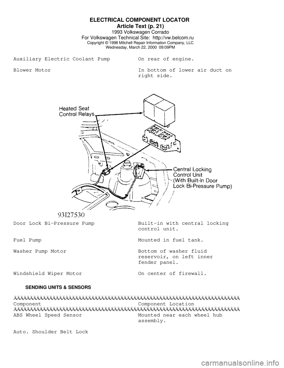
right side.Door Lock Bi-Pressure Pump Built-in with central locking
control unit.
Fuel Pump Mounted in fuel tank.
Washer Pump Motor Bottom of washer fluid
reservoir, on left inner
fender panel.
Windshield Wiper Motor On center of firewall.
SENDING UNITS & SENSORSÄÄÄÄÄÄÄÄÄÄÄÄÄÄÄÄÄÄÄÄÄÄÄÄÄÄÄÄÄÄÄÄÄÄÄÄÄÄÄÄÄÄÄÄÄÄÄÄÄÄÄÄÄÄÄÄÄÄÄÄÄÄÄÄÄÄÄÄÄÄComponent Component Location
ÄÄÄÄÄÄÄÄÄÄÄÄÄÄÄÄÄÄÄÄÄÄÄÄÄÄÄÄÄÄÄÄÄÄÄÄÄÄÄÄÄÄÄÄÄÄÄÄÄÄÄÄÄÄÄÄÄÄÄÄÄÄÄÄÄÄÄÄÄÄABS Wheel Speed Sensor Mounted near each wheel hub
assembly.
Auto. Shoulder Belt Lock
Page 495 of 920

D - ADJUSTMENTS
Article Text (p. 2)
1993 Volkswagen Corrado
For Volkswagen Technical Site: http://vw.belcom.ru
Copyright © 1998 Mitchell Repair Information Company, LLC
Wednesday, March 22, 2000 08:59PM
function by pressing right arrow button. Press "0" and "6" for END
OUTPUT function. Press "Q" button to enter input.
8) If idle speed, CO level or ignition timing is incorrect,
turn ignition off. Check accelerator pedal and throttle cable for ease
of operation. Check dashpot adjustment. Check throttle position
sensor, idle air control valve, and EGR valve.
IDLE SPEED & MIXTURE
NOTE: Mixture adjustment is NOT a part of normal tune-up procedure
and should not be performed unless mixture control unit is
replaced or vehicle fails emissions testing.
NOTE: Ensure fuel system pressure is correct before attempting
idle speed or mixture adjustment.
VR6 IDLE SPEED & MIXTURE ADJUSTMENT
See VR6 IGNITION TIMING under IGNITION TIMING near the
beginning of this article.
THROTTLE BODY
THROTTLE BODY ADJUSTMENT
CAUTION: Throttle limiting (stop) screw is set by manufacturer and
should NOT be moved. If screw is accidentally turned,
perform throttle body adjustment.
If stop screw for basic throttle adjustment has been moved,
replace throttle body.
DASHPOT
Open and close throttle until dashpot piston contacts roller.
With throttle in this position, check gap between limiter (stop) screw
and throttle. Gap between limiter (stop) screw and throttle lever must
be 0.10-0.14" (2.5-3.5 mm).
IDLE & FULL THROTTLE SWITCHES
THROTTLE POSITION (TP) SENSOR ADJUSTMENT
1) Connect Scan Tester (VAG 1551) to Data Link Connectors
(DLC) located in center console, in front of shift lever. Turn
ignition on. Operate scan tester and select RAPID DATA TRANSFER,
ENGINE ELECTRONICS, then READ MEASURING VALUE BLOCK functions.
2) Press "0" and "3" buttons to select INSERT DISPLAY GROUP
NUMBER 03 function. Press "Q" button to enter input. Slowly open
throttle, while observing display in channel 3, until throttle is wide
open. Numerical value must increase uniformly over entire opening
Page 503 of 920

DOOR LOCKS - POWER
Article Text (p. 5)
1993 Volkswagen Corrado
For Volkswagen Technical Site: http://vw.belcom.ru
Copyright © 1998 Mitchell Repair Information Company, LLC
Wednesday, March 22, 2000 09:08PM
FUEL DOOR ACTIVATOR
Removal & Installation
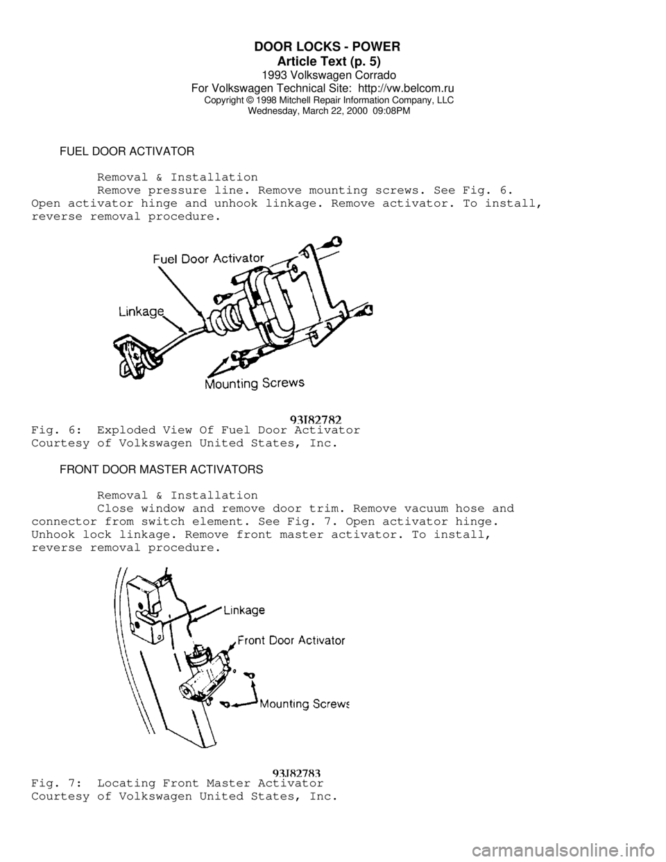
Remove pressure line. Remove mounting screws. See Fig. 6.
Open activator hinge and unhook linkage. Remove activator. To install,
reverse removal procedure.Fig. 6: Exploded View Of Fuel Door Activator
Courtesy of Volkswagen United States, Inc.
FRONT DOOR MASTER ACTIVATORS
Removal & Installation
Close window and remove door trim. Remove vacuum hose and
connector from switch element. See Fig. 7. Open activator hinge.
Unhook lock linkage. Remove front master activator. To install,
reverse removal procedure.Fig. 7: Locating Front Master Activator
Courtesy of Volkswagen United States, Inc.
Page 509 of 920

E - THEORY/OPERATION
Article Text (p. 4)
1993 Volkswagen Corrado
For Volkswagen Technical Site: http://vw.belcom.ru
Copyright © 1998 Mitchell Repair Information Company, LLC
Wednesday, March 22, 2000 09:09PM
Fuel Injectors
See FUEL CONTROL under FUEL SYSTEM in this article.
Fuel Pump
See FUEL DELIVERY under FUEL SYSTEM in this article.
Idle Air Control/Stabilizer Valve
See IDLE SPEED under FUEL SYSTEM in this article.
Ignition Coil & Output Stage
See DISTRIBUTORLESS IGNITION SYSTEM (DIS) under IGNITION
SYSTEM in this article.
Malfunction Indicator (CHECK ENGINE) Light
See MALFUNCTION INDICATOR (CHECK ENGINE) LIGHT under SELF-
DIAGNOSTIC SYSTEM in this article.
FUEL SYSTEM
FUEL DELIVERY
Fuel Pump
A 2-stage fuel pump, located in fuel tank, is used (one motor
drives two separate pumps). The stage one vane-type pump draws fuel,
through a screen, from bottom of fuel tank and into an accumulator.
The vane-type pump acts as a transfer pump. The stage two gear-type
pump draws fuel from bottom of accumulator and out fuel lines.
Fuel Pressure Regulator
The diaphragm-type fuel pressure regulator is attached to
fuel return side of fuel rail. Fuel pressure is regulated depending on
intake manifold pressure. As intake manifold pressure changes, the
pressure regulator will increase or decrease fuel system pressure.
FUEL CONTROL
Fuel Injectors
Fuel injectors are supplied with battery (system) voltage
through power supply relay and are controlled (grounded) by the ECM.
Injectors are opened sequentially in cylinder firing order. Fuel
quantity is determined by injector on time (duty cycle).
IDLE SPEED
Idle Air Control/Stabilizer Valve
The idle air control/stabilizer valve is actuated by the ECM
thorough the valve's ground control circuit. When a defect in circuit
is recognized, both output stages are shut-off and the valve rotates
to a fixed potion. This permits engine to idle at a warm engine idle
speed.
IGNITION SYSTEM
Page 517 of 920

EMISSION CONTROL VISUAL INSPECTION PROCEDURES
Article Text (p. 3)
1993 Volkswagen Corrado
For Volkswagen Technical Site: http://vw.belcom.ru
Copyright © 1998 Mitchell Repair Information Company, LLC
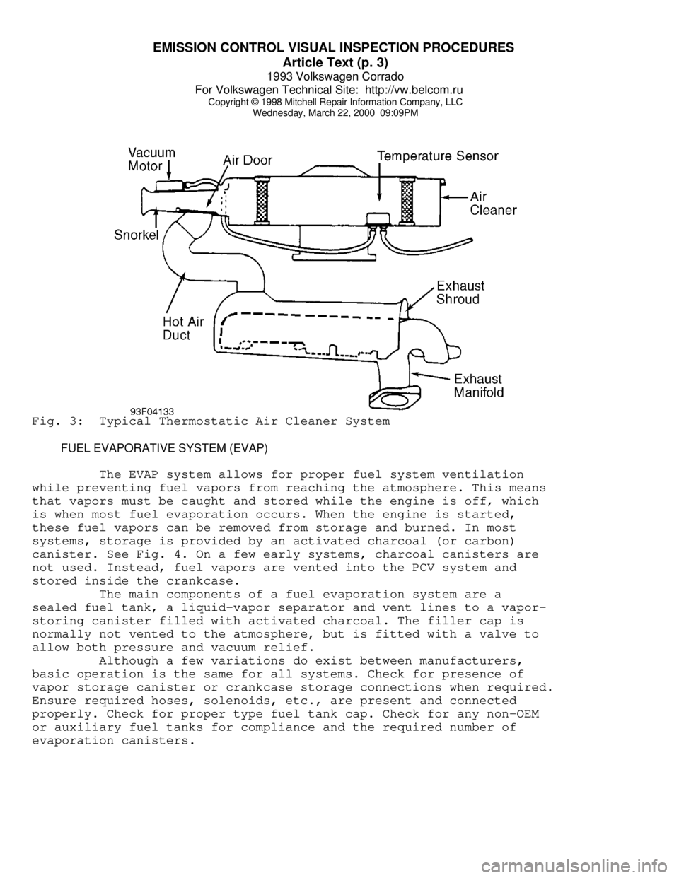
Wednesday, March 22, 2000 09:09PMFig. 3: Typical Thermostatic Air Cleaner System
FUEL EVAPORATIVE SYSTEM (EVAP)
The EVAP system allows for proper fuel system ventilation
while preventing fuel vapors from reaching the atmosphere. This means
that vapors must be caught and stored while the engine is off, which
is when most fuel evaporation occurs. When the engine is started,
these fuel vapors can be removed from storage and burned. In most
systems, storage is provided by an activated charcoal (or carbon)
canister. See Fig. 4. On a few early systems, charcoal canisters are
not used. Instead, fuel vapors are vented into the PCV system and
stored inside the crankcase.
The main components of a fuel evaporation system are a
sealed fuel tank, a liquid-vapor separator and vent lines to a vapor-
storing canister filled with activated charcoal. The filler cap is
normally not vented to the atmosphere, but is fitted with a valve to
allow both pressure and vacuum relief.
Although a few variations do exist between manufacturers,
basic operation is the same for all systems. Check for presence of
vapor storage canister or crankcase storage connections when required.
Ensure required hoses, solenoids, etc., are present and connected
properly. Check for proper type fuel tank cap. Check for any non-OEM
or auxiliary fuel tanks for compliance and the required number of
evaporation canisters.