1993 FORD MONDEO sensor
[x] Cancel search: sensorPage 168 of 279
actual links stationary while the nuts are being
unscrewed, to prevent damage to the joints.
Swivel the anti-roll bar upwards, and recover
the rubber bushes.
5Where applicable, remove the ABS wheel
sensor from the rear suspension knuckle as
described in Chapter 9.
6Unscrew and remove the bolts, and
disconnect both lower arms from the rear
suspension knuckle.
7To allow the rear suspension struts to be
released from the rubber stops on the top of
the crossmember, it is necessary to fit coil
spring compressor tools to both of the rear
coil springs, and compress them until all
tension is removed from the upper and lower
mountings.
Warning: It is important to only
use high-quality spring
compressors, and to carefully
follow the tool manufacturer’s
instructions provided with them. With the
compressor tools fitted, support the struts
to one side.
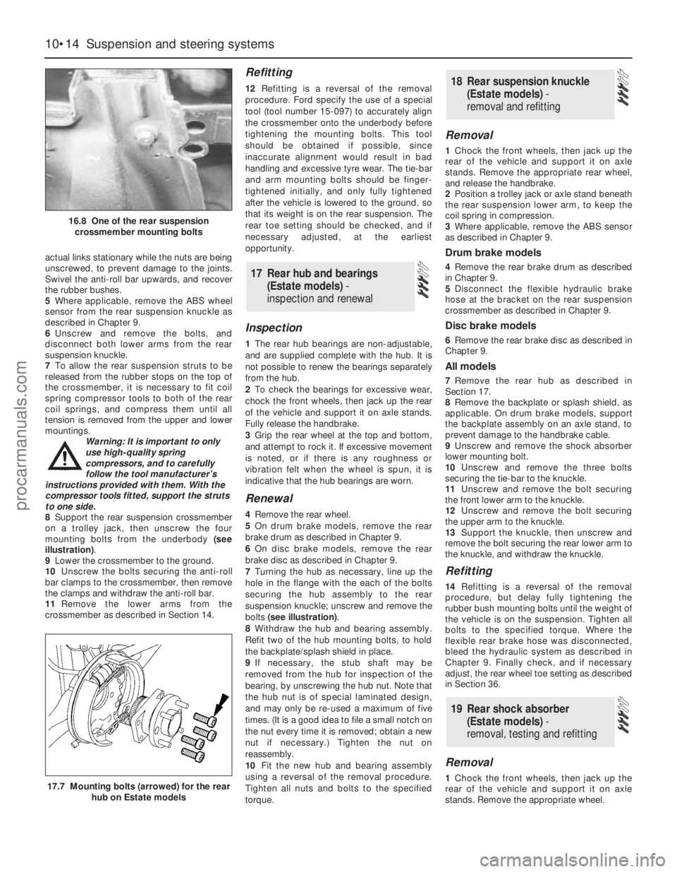
8Support the rear suspension crossmember
on a trolley jack, then unscrew the four
mounting bolts from the underbody (see
illustration).
9Lower the crossmember to the ground.
10Unscrew the bolts securing the anti-roll
bar clamps to the crossmember, then remove
the clamps and withdraw the anti-roll bar.
11Remove the lower arms from the
crossmember as described in Section 14.
Refitting
12Refitting is a reversal of the removal
procedure. Ford specify the use of a special
tool (tool number 15-097) to accurately align
the crossmember onto the underbody before
tightening the mounting bolts. This tool
should be obtained if possible, since
inaccurate alignment would result in bad
handling and excessive tyre wear. The tie-bar
and arm mounting bolts should be finger-
tightened initially, and only fully tightened
after the vehicle is lowered to the ground, so
that its weight is on the rear suspension. The
rear toe setting should be checked, and if
necessary adjusted, at the earliest
opportunity.
Inspection
1The rear hub bearings are non-adjustable,
and are supplied complete with the hub. It is
not possible to renew the bearings separately
from the hub.
2To check the bearings for excessive wear,
chock the front wheels, then jack up the rear
of the vehicle and support it on axle stands.
Fully release the handbrake.
3Grip the rear wheel at the top and bottom,
and attempt to rock it. If excessive movement
is noted, or if there is any roughness or
vibration felt when the wheel is spun, it is
indicative that the hub bearings are worn.
Renewal
4Remove the rear wheel.
5On drum brake models, remove the rear
brake drum as described in Chapter 9.
6On disc brake models, remove the rear
brake disc as described in Chapter 9.
7Turning the hub as necessary, line up the
hole in the flange with the each of the bolts
securing the hub assembly to the rear
suspension knuckle; unscrew and remove the
bolts (see illustration).
8Withdraw the hub and bearing assembly.
Refit two of the hub mounting bolts, to hold
the backplate/splash shield in place.
9If necessary, the stub shaft may be
removed from the hub for inspection of the
bearing, by unscrewing the hub nut. Note that
the hub nut is of special laminated design,
and may only be re-used a maximum of five
times. (It is a good idea to file a small notch on
the nut every time it is removed; obtain a new
nut if necessary.) Tighten the nut on
reassembly.
10Fit the new hub and bearing assembly
using a reversal of the removal procedure.
Tighten all nuts and bolts to the specified
torque.
Removal
1Chock the front wheels, then jack up the
rear of the vehicle and support it on axle
stands. Remove the appropriate rear wheel,
and release the handbrake.
2Position a trolley jack or axle stand beneath
the rear suspension lower arm, to keep the
coil spring in compression.
3Where applicable, remove the ABS sensor
as described in Chapter 9.
Drum brake models
4Remove the rear brake drum as described
in Chapter 9.
5Disconnect the flexible hydraulic brake
hose at the bracket on the rear suspension
crossmember as described in Chapter 9.
Disc brake models
6Remove the rear brake disc as described in
Chapter 9.
All models
7Remove the rear hub as described in
Section 17.
8Remove the backplate or splash shield, as
applicable. On drum brake models, support
the backplate assembly on an axle stand, to
prevent damage to the handbrake cable.
9Unscrew and remove the shock absorber
lower mounting bolt.
10Unscrew and remove the three bolts
securing the tie-bar to the knuckle.
11Unscrew and remove the bolt securing
the front lower arm to the knuckle.
12Unscrew and remove the bolt securing
the upper arm to the knuckle.
13Support the knuckle, then unscrew and
remove the bolt securing the rear lower arm to
the knuckle, and withdraw the knuckle.
Refitting
14Refitting is a reversal of the removal
procedure, but delay fully tightening the
rubber bush mounting bolts until the weight of
the vehicle is on the suspension. Tighten all
bolts to the specified torque. Where the
flexible rear brake hose was disconnected,
bleed the hydraulic system as described in
Chapter 9. Finally check, and if necessary
adjust, the rear wheel toe setting as described
in Section 36.
Removal
1Chock the front wheels, then jack up the
rear of the vehicle and support it on axle
stands. Remove the appropriate wheel.
19 Rear shock absorber
(Estate models) -
removal, testing and refitting
18 Rear suspension knuckle
(Estate models) -
removal and refitting
17 Rear hub and bearings
(Estate models) -
inspection and renewal
10•14 Suspension and steering systems
16.8 One of the rear suspension
crossmember mounting bolts
17.7 Mounting bolts (arrowed) for the rear
hub on Estate models
procarmanuals.com
Page 171 of 279
2Using a trolley jack, support the rear lower
arm beneath the coil spring position.
3Unscrew and remove the bolt securing the
rear shock absorber to the knuckle.
4Where applicable, release the ABS wheel
sensor lead from the tie-bar.
5Detach the handbrake cable from the tie-
bar bracket.
6Refer to Chapter 9, and disconnect the
handbrake cable from the rear brake shoes or
rear caliper, as applicable. Pass the cable
through the hole in the tie-bar.
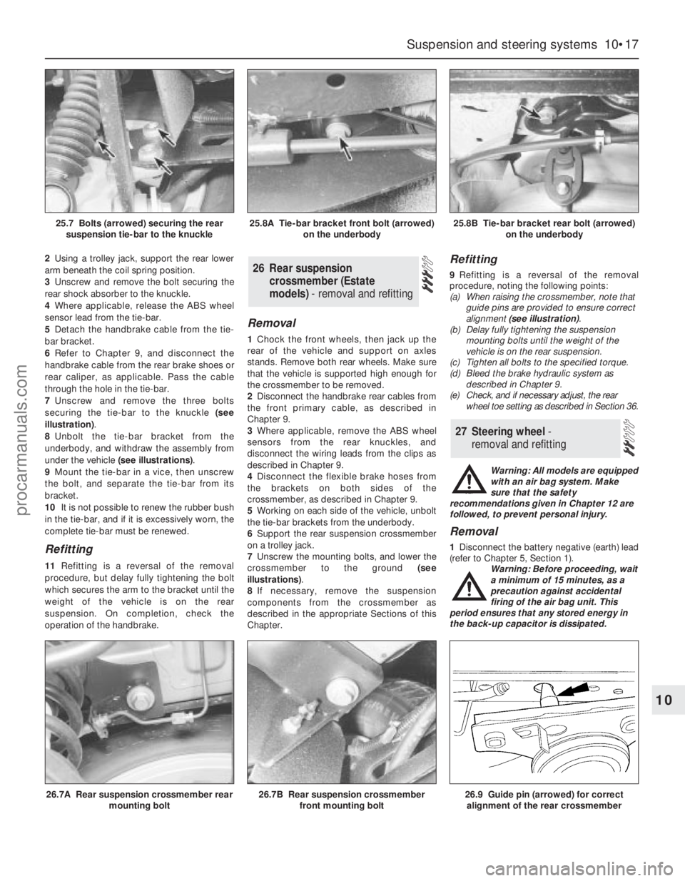
7Unscrew and remove the three bolts
securing the tie-bar to the knuckle (see
illustration).
8Unbolt the tie-bar bracket from the
underbody, and withdraw the assembly from
under the vehicle (see illustrations).
9Mount the tie-bar in a vice, then unscrew
the bolt, and separate the tie-bar from its
bracket.
10It is not possible to renew the rubber bush
in the tie-bar, and if it is excessively worn, the
complete tie-bar must be renewed.
Refitting
11Refitting is a reversal of the removal
procedure, but delay fully tightening the bolt
which secures the arm to the bracket until the
weight of the vehicle is on the rear
suspension. On completion, check the
operation of the handbrake.
Removal
1Chock the front wheels, then jack up the
rear of the vehicle and support on axles
stands. Remove both rear wheels. Make sure
that the vehicle is supported high enough for
the crossmember to be removed.
2Disconnect the handbrake rear cables from
the front primary cable, as described in
Chapter 9.
3Where applicable, remove the ABS wheel
sensors from the rear knuckles, and
disconnect the wiring leads from the clips as
described in Chapter 9.
4Disconnect the flexible brake hoses from
the brackets on both sides of the
crossmember, as described in Chapter 9.
5Working on each side of the vehicle, unbolt
the tie-bar brackets from the underbody.
6Support the rear suspension crossmember
on a trolley jack.
7Unscrew the mounting bolts, and lower the
crossmember to the ground (see
illustrations).
8If necessary, remove the suspension
components from the crossmember as
described in the appropriate Sections of this
Chapter.
Refitting
9Refitting is a reversal of the removal
procedure, noting the following points:
(a) When raising the crossmember, note that
guide pins are provided to ensure correct
alignment (see illustration).
(b) Delay fully tightening the suspension
mounting bolts until the weight of the
vehicle is on the rear suspension.
(c) Tighten all bolts to the specified torque.
(d) Bleed the brake hydraulic system as
described in Chapter 9.
(e) Check, and if necessary adjust, the rear
wheel toe setting as described in Section 36.
Warning: All models are equipped
with an air bag system. Make
sure that the safety
recommendations given in Chapter 12 are
followed, to prevent personal injury.
Removal
1Disconnect the battery negative (earth) lead
(refer to Chapter 5, Section 1).
Warning: Before proceeding, wait
a minimum of 15 minutes, as a
precaution against accidental
firing of the air bag unit. This
period ensures that any stored energy in
the back-up capacitor is dissipated.
27 Steering wheel -
removal and refitting
26 Rear suspension
crossmember (Estate
models) - removal and refitting
Suspension and steering systems 10•17
10
26.7A Rear suspension crossmember rear
mounting bolt26.7B Rear suspension crossmember
front mounting bolt26.9 Guide pin (arrowed) for correct
alignment of the rear crossmember
25.7 Bolts (arrowed) securing the rear
suspension tie-bar to the knuckle25.8A Tie-bar bracket front bolt (arrowed)
on the underbody25.8B Tie-bar bracket rear bolt (arrowed)
on the underbody
procarmanuals.com
Page 175 of 279
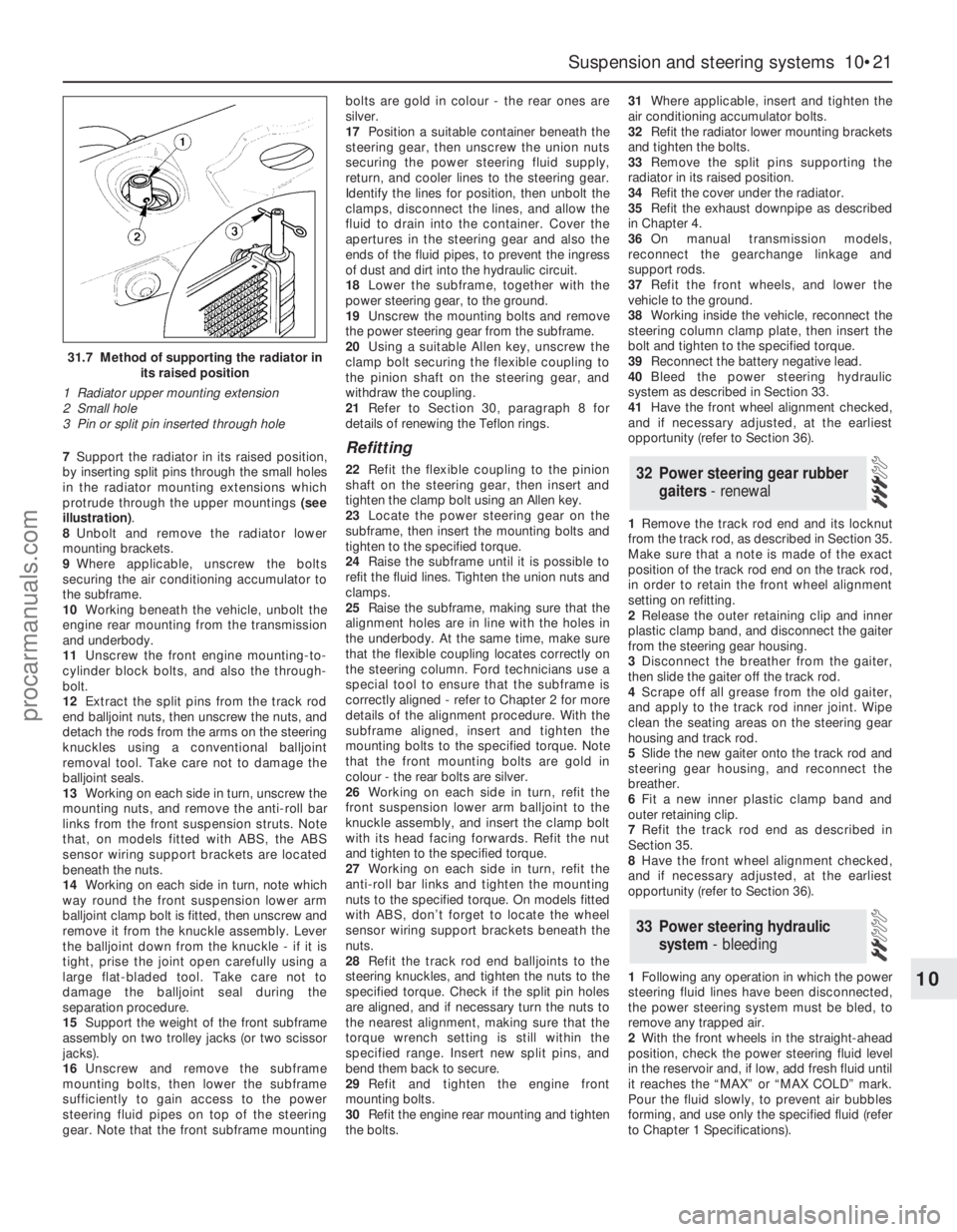
7Support the radiator in its raised position,
by inserting split pins through the small holes
in the radiator mounting extensions which
protrude through the upper mountings (see
illustration).
8Unbolt and remove the radiator lower
mounting brackets.
9Where applicable, unscrew the bolts
securing the air conditioning accumulator to
the subframe.
10Working beneath the vehicle, unbolt the
engine rear mounting from the transmission
and underbody.
11Unscrew the front engine mounting-to-
cylinder block bolts, and also the through-
bolt.
12Extract the split pins from the track rod
end balljoint nuts, then unscrew the nuts, and
detach the rods from the arms on the steering
knuckles using a conventional balljoint
removal tool. Take care not to damage the
balljoint seals.
13Working on each side in turn, unscrew the
mounting nuts, and remove the anti-roll bar
links from the front suspension struts. Note
that, on models fitted with ABS, the ABS
sensor wiring support brackets are located
beneath the nuts.
14Working on each side in turn, note which
way round the front suspension lower arm
balljoint clamp bolt is fitted, then unscrew and
remove it from the knuckle assembly. Lever
the balljoint down from the knuckle - if it is
tight, prise the joint open carefully using a
large flat-bladed tool. Take care not to
damage the balljoint seal during the
separation procedure.
15Support the weight of the front subframe
assembly on two trolley jacks (or two scissor
jacks).
16Unscrew and remove the subframe
mounting bolts, then lower the subframe
sufficiently to gain access to the power
steering fluid pipes on top of the steering
gear. Note that the front subframe mountingbolts are gold in colour - the rear ones are
silver.
17Position a suitable container beneath the
steering gear, then unscrew the union nuts
securing the power steering fluid supply,
return, and cooler lines to the steering gear.
Identify the lines for position, then unbolt the
clamps, disconnect the lines, and allow the
fluid to drain into the container. Cover the
apertures in the steering gear and also the
ends of the fluid pipes, to prevent the ingress
of dust and dirt into the hydraulic circuit.
18Lower the subframe, together with the
power steering gear, to the ground.
19Unscrew the mounting bolts and remove
the power steering gear from the subframe.
20Using a suitable Allen key, unscrew the
clamp bolt securing the flexible coupling to
the pinion shaft on the steering gear, and
withdraw the coupling.
21Refer to Section 30, paragraph 8 for
details of renewing the Teflon rings.Refitting
22Refit the flexible coupling to the pinion
shaft on the steering gear, then insert and
tighten the clamp bolt using an Allen key.
23Locate the power steering gear on the
subframe, then insert the mounting bolts and
tighten to the specified torque.
24Raise the subframe until it is possible to
refit the fluid lines. Tighten the union nuts and
clamps.
25Raise the subframe, making sure that the
alignment holes are in line with the holes in
the underbody. At the same time, make sure
that the flexible coupling locates correctly on
the steering column. Ford technicians use a
special tool to ensure that the subframe is
correctly aligned - refer to Chapter 2 for more
details of the alignment procedure. With the
subframe aligned, insert and tighten the
mounting bolts to the specified torque. Note
that the front mounting bolts are gold in
colour - the rear bolts are silver.
26Working on each side in turn, refit the
front suspension lower arm balljoint to the
knuckle assembly, and insert the clamp bolt
with its head facing forwards. Refit the nut
and tighten to the specified torque.
27Working on each side in turn, refit the
anti-roll bar links and tighten the mounting
nuts to the specified torque. On models fitted
with ABS, don’t forget to locate the wheel
sensor wiring support brackets beneath the
nuts.
28Refit the track rod end balljoints to the
steering knuckles, and tighten the nuts to the
specified torque. Check if the split pin holes
are aligned, and if necessary turn the nuts to
the nearest alignment, making sure that the
torque wrench setting is still within the
specified range. Insert new split pins, and
bend them back to secure.
29Refit and tighten the engine front
mounting bolts.
30Refit the engine rear mounting and tighten
the bolts.31Where applicable, insert and tighten the
air conditioning accumulator bolts.
32Refit the radiator lower mounting brackets
and tighten the bolts.
33Remove the split pins supporting the
radiator in its raised position.
34Refit the cover under the radiator.
35Refit the exhaust downpipe as described
in Chapter 4.
36On manual transmission models,
reconnect the gearchange linkage and
support rods.
37Refit the front wheels, and lower the
vehicle to the ground.
38Working inside the vehicle, reconnect the
steering column clamp plate, then insert the
bolt and tighten to the specified torque.
39Reconnect the battery negative lead.
40Bleed the power steering hydraulic
system as described in Section 33.
41Have the front wheel alignment checked,
and if necessary adjusted, at the earliest
opportunity (refer to Section 36).
1Remove the track rod end and its locknut
from the track rod, as described in Section 35.
Make sure that a note is made of the exact
position of the track rod end on the track rod,
in order to retain the front wheel alignment
setting on refitting.
2Release the outer retaining clip and inner
plastic clamp band, and disconnect the gaiter
from the steering gear housing.
3Disconnect the breather from the gaiter,
then slide the gaiter off the track rod.
4Scrape off all grease from the old gaiter,
and apply to the track rod inner joint. Wipe
clean the seating areas on the steering gear
housing and track rod.
5Slide the new gaiter onto the track rod and
steering gear housing, and reconnect the
breather.
6Fit a new inner plastic clamp band and
outer retaining clip.
7Refit the track rod end as described in
Section 35.
8Have the front wheel alignment checked,
and if necessary adjusted, at the earliest
opportunity (refer to Section 36).
1Following any operation in which the power
steering fluid lines have been disconnected,
the power steering system must be bled, to
remove any trapped air.
2With the front wheels in the straight-ahead
position, check the power steering fluid level
in the reservoir and, if low, add fresh fluid until
it reaches the “MAX” or “MAX COLD” mark.
Pour the fluid slowly, to prevent air bubbles
forming, and use only the specified fluid (refer
to Chapter 1 Specifications).
33 Power steering hydraulic
system - bleeding
32 Power steering gear rubber
gaiters - renewal
Suspension and steering systems 10•21
10
31.7 Method of supporting the radiator in
its raised position
1 Radiator upper mounting extension
2 Small hole
3 Pin or split pin inserted through hole
procarmanuals.com
Page 178 of 279
Chapter 11 Bodywork and fittings
Body side-trim mouldings and adhesive emblems - removal
and refitting . . . . . . . . . . . . . . . . . . . . . . . . . . . . . . . . . . . . . . . . . . 25
Bonnet - removal, refitting and adjustment . . . . . . . . . . . . . . . . . . . . 8
Bonnet lock - removal, refitting and adjustment . . . . . . . . . . . . . . . . 10
Bonnet release cable and lever - removal and refitting . . . . . . . . . . . 9
Boot lid - removal and refitting . . . . . . . . . . . . . . . . . . . . . . . . . . . . . 18
Boot lid lock components - removal and refitting . . . . . . . . . . . . . . . 19
Bumpers - removal and refitting . . . . . . . . . . . . . . . . . . . . . . . . . . . . 6
Central locking system components - testing, removal and refitting . 23
Centre console - removal and refitting . . . . . . . . . . . . . . . . . . . . . . . 30
Door - removal and refitting . . . . . . . . . . . . . . . . . . . . . . . . . . . . . . . 15
Door handle and lock components - removal and refitting . . . . . . . . 14
Door inner trim panel - removal and refitting . . . . . . . . . . . . . . . . . . 11
Door window glass - removal and refitting . . . . . . . . . . . . . . . . . . . . 12
Door window regulator - removal and refitting . . . . . . . . . . . . . . . . . 13
Exterior mirror and glass - removal and refitting . . . . . . . . . . . . . . . . 16
Facia - removal and refitting . . . . . . . . . . . . . . . . . . . . . . . . . . . . . . . 33
General information . . . . . . . . . . . . . . . . . . . . . . . . . . . . . . . . . . . . . . 1Glovebox - removal and refitting . . . . . . . . . . . . . . . . . . . . . . . . . . . . 32
Interior mirror - removal and refitting . . . . . . . . . . . . . . . . . . . . . . . . 17
Interior trim panels - removal and refitting . . . . . . . . . . . . . . . . . . . . 29
Maintenance - bodywork and underframe . . . . . . . . . . . . . . . . . . . . 2
Maintenance - upholstery and carpets . . . . . . . . . . . . . . . . . . . . . . . 3
Major body damage - repair . . . . . . . . . . . . . . . . . . . . . . . . . . . . . . . 5
Minor body damage - repair . . . . . . . . . . . . . . . . . . . . . . . . . . . . . . . 4
Overhead console - removal and refitting . . . . . . . . . . . . . . . . . . . . . 31
Radiator grille - removal and refitting . . . . . . . . . . . . . . . . . . . . . . . . 7
Seat belts - removal and refitting . . . . . . . . . . . . . . . . . . . . . . . . . . . 28
Seats - removal and refitting . . . . . . . . . . . . . . . . . . . . . . . . . . . . . . . 27
Sunroof - general information and adjustment . . . . . . . . . . . . . . . . . 26
Tailgate - removal and refitting . . . . . . . . . . . . . . . . . . . . . . . . . . . . . 20
Tailgate lock components - removal and refitting . . . . . . . . . . . . . . . 22
Tailgate support strut - removal and refitting . . . . . . . . . . . . . . . . . . 21
Wheel arch liner - removal and refitting . . . . . . . . . . . . . . . . . . . . . . 34
Windscreen and fixed windows - removal and refitting . . . . . . . . . . 24
Torque wrench settingsNm lbf ft
Bonnet and tailgate hinges . . . . . . . . . . . . . . . . . . . . . . . . . . . . . . . . . . . 24 18
Boot lid . . . . . . . . . . . . . . . . . . . . . . . . . . . . . . . . . . . . . . . . . . . . . . . . . . 10 7
Front seat mounting bolts . . . . . . . . . . . . . . . . . . . . . . . . . . . . . . . . . . . . 38 28
Seat belt mounting nuts and bolts . . . . . . . . . . . . . . . . . . . . . . . . . . . . . 38 28
Bumper mounting nuts . . . . . . . . . . . . . . . . . . . . . . . . . . . . . . . . . . . . . . 10 7
11•1
Easy,suitable for
novice with little
experienceFairly easy,suitable
for beginner with
some experienceFairly difficult,suitable
for competent DIY
mechanicDifficult,suitable for
experienced DIY
mechanicVery difficult,
suitable for expert DIY
or professional
Degrees of difficulty
Specifications Contents
11
The bodyshell and underframe on all
models is of all-steel welded construction,
incorporating progressive crumple zones at
the front and rear, and a rigid centre safety
cell. The bulkhead behind the engine
compartment incorporates crash grooves
which determine its energy-absorption
characteristics, and special beams to prevent
the intrusion of the front wheels into the
passenger compartment during a serious
accident. All passenger doors incorporate
side impact bars.
All sheet metal surfaces which are prone tocorrosion are galvanized. The painting
process includes a base colour which closely
matches the final topcoat, so that any stone
damage is not noticeable.
Hatchback, Saloon and Estate versions are
available. The front section of the vehicle up to
the “B” pillar is identical on all models.
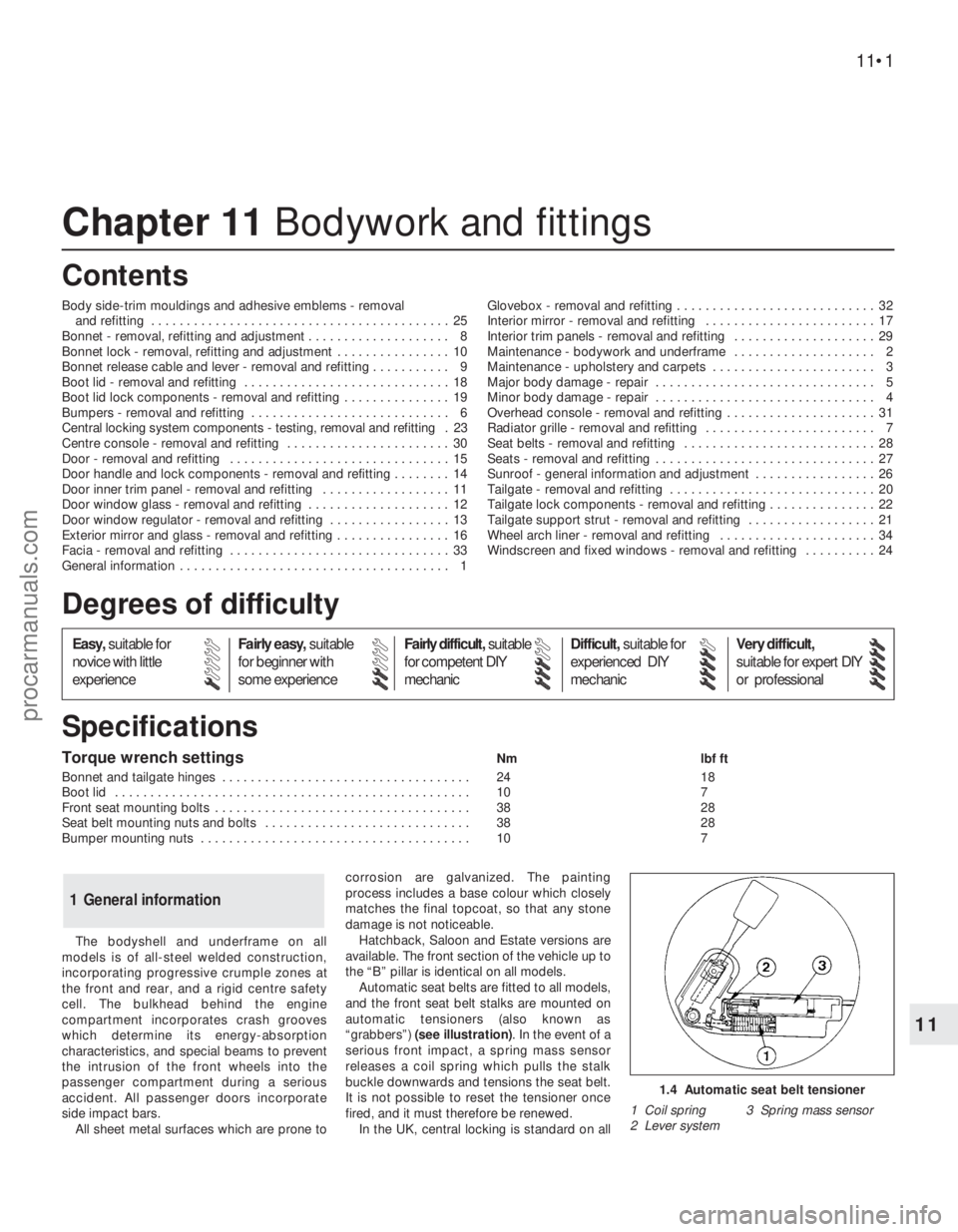
Automatic seat belts are fitted to all models,
and the front seat belt stalks are mounted on
automatic tensioners (also known as
“grabbers”) (see illustration). In the event of a
serious front impact, a spring mass sensor
releases a coil spring which pulls the stalk
buckle downwards and tensions the seat belt.
It is not possible to reset the tensioner once
fired, and it must therefore be renewed.
In the UK, central locking is standard on all
1 General information
1.4 Automatic seat belt tensioner
1 Coil spring 3 Spring mass sensor
2 Lever system
procarmanuals.com
Page 179 of 279
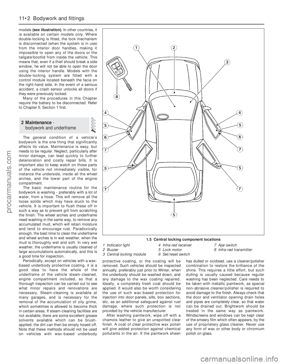
models (see illustration). In other countries, it
is available on certain models only. Where
double-locking is fitted, the lock mechanism
is disconnected (when the system is in use)
from the interior door handles, making it
impossible to open any of the doors or the
tailgate/bootlid from inside the vehicle. This
means that, even if a thief should break a side
window, he will not be able to open the door
using the interior handle. Models with the
double-locking system are fitted with a
control module located beneath the facia on
the right-hand side. In the event of a serious
accident, a crash sensor unlocks all doors if
they were previously locked.
Many of the procedures in this Chapter
require the battery to be disconnected. Refer
to Chapter 5, Section 1 first.
The general condition of a vehicle’s
bodywork is the one thing that significantly
affects its value. Maintenance is easy, but
needs to be regular. Neglect, particularly after
minor damage, can lead quickly to further
deterioration and costly repair bills. It is
important also to keep watch on those parts
of the vehicle not immediately visible, for
instance the underside, inside all the wheel
arches, and the lower part of the engine
compartment.
The basic maintenance routine for the
bodywork is washing - preferably with a lot of
water, from a hose. This will remove all the
loose solids which may have stuck to the
vehicle. It is important to flush these off in
such a way as to prevent grit from scratching
the finish. The wheel arches and underframe
need washing in the same way, to remove any
accumulated mud, which will retain moisture
and tend to encourage rust. Paradoxically
enough, the best time to clean the underframe
and wheel arches is in wet weather, when the
mud is thoroughly wet and soft. In very wet
weather, the underframe is usually cleaned of
large accumulations automatically, and this is
a good time for inspection.
Periodically, except on vehicles with a wax-
based underbody protective coating, it is a
good idea to have the whole of the
underframe of the vehicle steam-cleaned,
engine compartment included, so that a
thorough inspection can be carried out to see
what minor repairs and renovations are
necessary. Steam-cleaning is available at
many garages, and is necessary for the
removal of the accumulation of oily grime,
which sometimes is allowed to become thick
in certain areas. If steam-cleaning facilities are
not available, there are some excellent grease
solvents available which can be brush-
applied; the dirt can then be simply hosed off.
Note that these methods should not be used
on vehicles with wax-based underbodyprotective coating, or the coating will be
removed. Such vehicles should be inspected
annually, preferably just prior to Winter, when
the underbody should be washed down, and
any damage to the wax coating repaired.
Ideally, a completely fresh coat should be
applied. It would also be worth considering
the use of such wax-based protection for
injection into door panels, sills, box sections,
etc, as an additional safeguard against rust
damage, where such protection is not
provided by the vehicle manufacturer.
After washing paintwork, wipe off with a
chamois leather to give an unspotted clear
finish. A coat of clear protective wax polish
will give added protection against chemical
pollutants in the air. If the paintwork sheenhas dulled or oxidised, use a cleaner/polisher
combination to restore the brilliance of the
shine. This requires a little effort, but such
dulling is usually caused because regular
washing has been neglected. Care needs to
be taken with metallic paintwork, as special
non-abrasive cleaner/polisher is required to
avoid damage to the finish. Always check that
the door and ventilator opening drain holes
and pipes are completely clear, so that water
can be drained out. Brightwork should be
treated in the same way as paintwork.
Windscreens and windows can be kept clear
of the smeary film which often appears, by the
use of proprietary glass cleaner. Never use
any form of wax or other body or chromium
polish on glass.
2 Maintenance -
bodywork and underframe
11•2 Bodywork and fittings
1.5 Central locking component locations
1 Indicator light
2 Buzzer
3 Central locking module4 Infra-red receiver
5 Lock motor
6 Set/reset switch7 Ajar switch
8 Infra-red transmitter
procarmanuals.com
Page 188 of 279
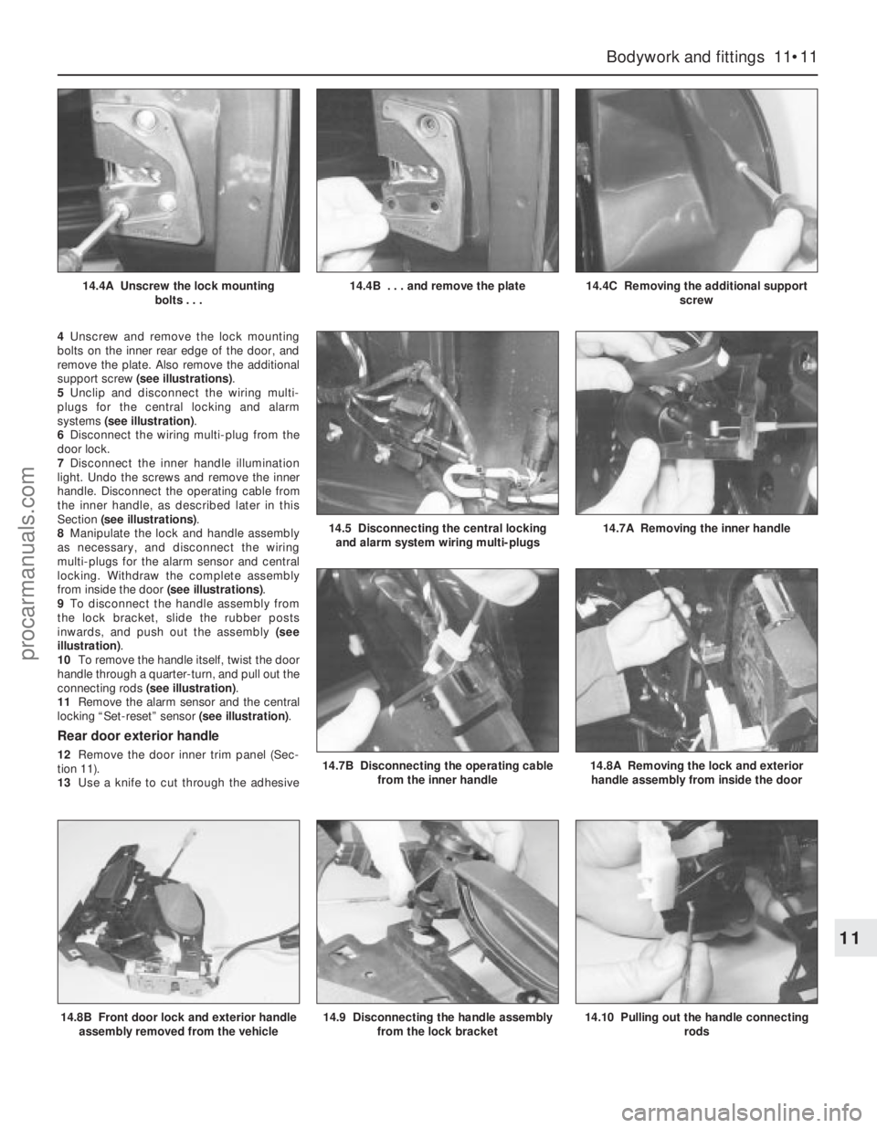
4Unscrew and remove the lock mounting
bolts on the inner rear edge of the door, and
remove the plate. Also remove the additional
support screw (see illustrations).
5Unclip and disconnect the wiring multi-
plugs for the central locking and alarm
systems (see illustration).
6Disconnect the wiring multi-plug from the
door lock.
7Disconnect the inner handle illumination
light. Undo the screws and remove the inner
handle. Disconnect the operating cable from
the inner handle, as described later in this
Section (see illustrations).
8Manipulate the lock and handle assembly
as necessary, and disconnect the wiring
multi-plugs for the alarm sensor and central
locking. Withdraw the complete assembly
from inside the door (see illustrations).
9To disconnect the handle assembly from
the lock bracket, slide the rubber posts
inwards, and push out the assembly (see
illustration).
10To remove the handle itself, twist the door
handle through a quarter-turn, and pull out the
connecting rods (see illustration).
11Remove the alarm sensor and the central
locking “Set-reset” sensor (see illustration).
Rear door exterior handle
12Remove the door inner trim panel (Sec-
tion 11).
13Use a knife to cut through the adhesive
Bodywork and fittings 11•11
11
14.8B Front door lock and exterior handle
assembly removed from the vehicle14.9 Disconnecting the handle assembly
from the lock bracket14.10 Pulling out the handle connecting
rods
14.4A Unscrew the lock mounting
bolts . . .14.4B . . . and remove the plate14.4C Removing the additional support
screw
14.5 Disconnecting the central locking
and alarm system wiring multi-plugs14.7A Removing the inner handle
14.7B Disconnecting the operating cable
from the inner handle14.8A Removing the lock and exterior
handle assembly from inside the door
procarmanuals.com
Page 189 of 279
strip, so that the foam insulator can be peeled
back for access to the lock. Do notpeel back
the foam insulator without first cutting through
the adhesive strip. To ensure a good seal
when the insulator is pressed back, do not
touch the adhesive strip.
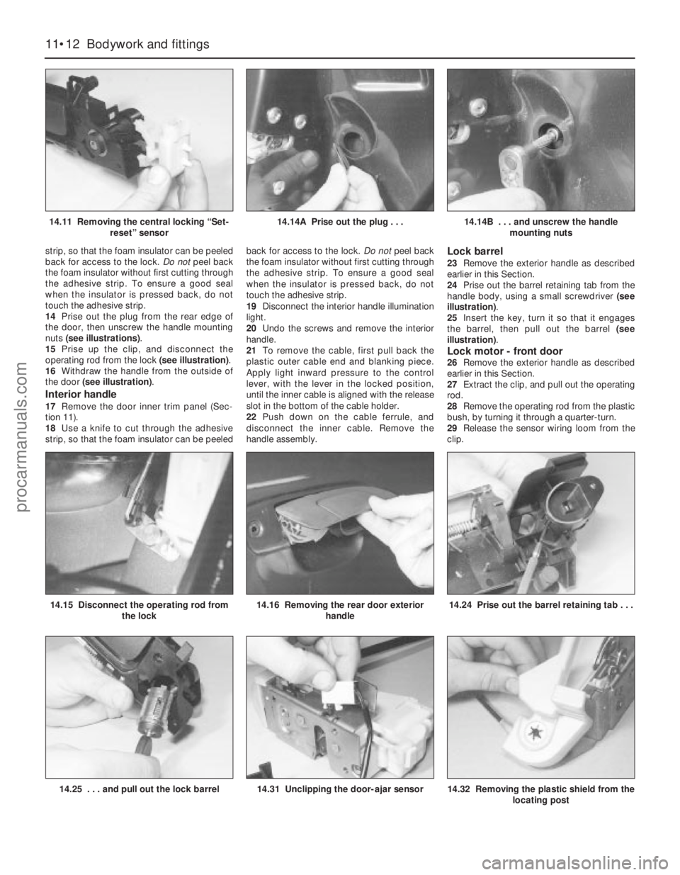
14Prise out the plug from the rear edge of
the door, then unscrew the handle mounting
nuts (see illustrations).
15Prise up the clip, and disconnect the
operating rod from the lock (see illustration).
16Withdraw the handle from the outside of
the door (see illustration).
Interior handle
17Remove the door inner trim panel (Sec-
tion 11).
18Use a knife to cut through the adhesive
strip, so that the foam insulator can be peeledback for access to the lock. Do notpeel back
the foam insulator without first cutting through
the adhesive strip. To ensure a good seal
when the insulator is pressed back, do not
touch the adhesive strip.
19Disconnect the interior handle illumination
light.
20Undo the screws and remove the interior
handle.
21To remove the cable, first pull back the
plastic outer cable end and blanking piece.
Apply light inward pressure to the control
lever, with the lever in the locked position,
until the inner cable is aligned with the release
slot in the bottom of the cable holder.
22Push down on the cable ferrule, and
disconnect the inner cable. Remove the
handle assembly.
Lock barrel
23Remove the exterior handle as described
earlier in this Section.
24Prise out the barrel retaining tab from the
handle body, using a small screwdriver (see
illustration).
25Insert the key, turn it so that it engages
the barrel, then pull out the barrel (see
illustration).
Lock motor - front door26Remove the exterior handle as described
earlier in this Section.
27Extract the clip, and pull out the operating
rod.
28Remove the operating rod from the plastic
bush, by turning it through a quarter-turn.
29Release the sensor wiring loom from the
clip.
11•12 Bodywork and fittings
14.11 Removing the central locking “Set-
reset” sensor14.14A Prise out the plug . . .14.14B . . . and unscrew the handle
mounting nuts
14.25 . . . and pull out the lock barrel14.31 Unclipping the door-ajar sensor14.32 Removing the plastic shield from the
locating post
14.15 Disconnect the operating rod from
the lock14.16 Removing the rear door exterior
handle14.24 Prise out the barrel retaining tab . . .
procarmanuals.com
Page 190 of 279
30Detach the mounting plate from the lock.
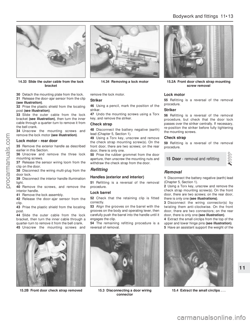
31Release the door-ajar sensor from the clip
(see illustration).
32Prise the plastic shield from the locating
post (see illustration).
33Slide the outer cable from the lock
bracket (see illustration), then turn the inner
cable through a quarter-turn to remove it from
the bell crank.
34Unscrew the mounting screws and
remove the lock motor (see illustration).
Lock motor - rear door
35Remove the exterior handle as described
earlier in this Section.
36Unscrew and remove the three lock
mounting screws.
37Release the sensor wiring loom from the
clip on the door.
38Disconnect the wiring multi-plug from the
door lock.
39Disconnect the interior handle illumination
light.
40Remove the screws, and remove the
interior handle.
41Remove the lock assembly.
42Release the door-ajar sensor from the
clip.
43Prise the plastic shield from the locating
post.
44Slide the outer cable from the lock
bracket, then turn the inner cable through a
quarter-turn to remove it from the bell crank.
45Unscrew the mounting screws andremove the lock motor.
Striker
46Using a pencil, mark the position of the
striker.
47Undo the mounting screws using a Torx
key, and remove the striker.
Check strap
48Disconnect the battery negative (earth)
lead (Chapter 5, Section 1).
49Using a Torx key, unscrew and remove
the check strap mounting screw(s). On the
front door, there are two screws; on the rear
door, there is only one.
50Prise the rubber grommet from the door
aperture, then unscrew the mounting nuts and
withdraw the check strap from the door.
Refitting
Handles (exterior and interior)
51Refitting is a reversal of the removal
procedure.
Lock barrel
52Check that the retaining clip is fitted
correctly.
53Align the grooves on the barrel with the
grooves on the body and operating lever, then
carefully push the barrel into the handle until it
engages the clip.
54The remaining refitting procedure is a
reversal of removal.
Lock motor
55Refitting is a reversal of the removal
procedure.
Striker
56Refitting is a reversal of the removal
procedure, but check that the door lock
passes over the striker centrally. If necessary,
re-position the striker before fully tightening
the mounting screws.
Check strap
59Refitting is a reversal of the removal
procedure.
Removal
1Disconnect the battery negative (earth) lead
(Chapter 5, Section 1).
2Using a Torx key, unscrew and remove the
check strap mounting screw(s). On the front
door, there are two screws; on the rear door,
there is only one (see illustrations).
3Disconnect the wiring connector(s) by
twisting them anti-clockwise. On the front
door, there are two connectors; on the rear
door, there is only one (see illustration).
4Extract the small circlips from the top of the
upper and lower hinge pins (see illustration).
5Have an assistant support the weight of the
15 Door - removal and refitting
Bodywork and fittings 11•13
11
15.2B Front door check strap removed15.3 Disconnecting a door wiring
connector15.4 Extract the small circlips . . .
14.33 Slide the outer cable from the lock
bracket14.34 Removing a lock motor15.2A Front door check strap mounting
screw removal
procarmanuals.com