1993 FORD MONDEO ESP
[x] Cancel search: ESPPage 142 of 279
6•8 Emissions control systems
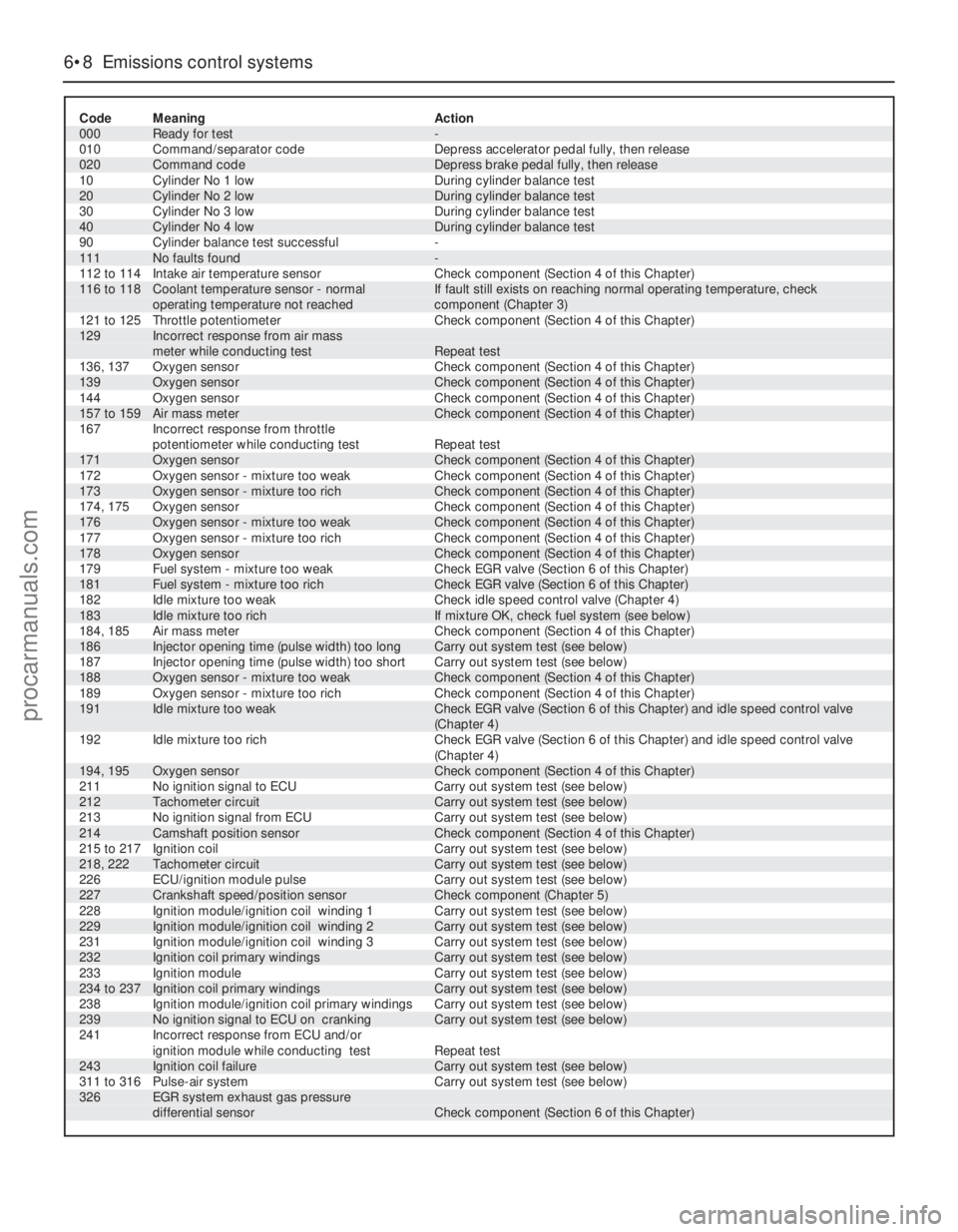
Code Meaning Action
000 Ready for test -
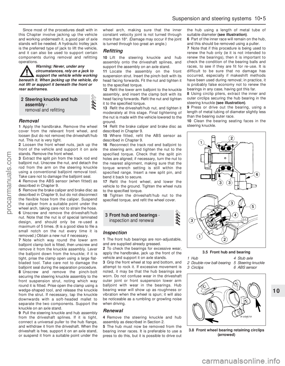
010 Command/separator code Depress accelerator pedal fully, then release
020 Command code Depress brake pedal fully, then release
10 Cylinder No 1 low During cylinder balance test
20 Cylinder No 2 low During cylinder balance test
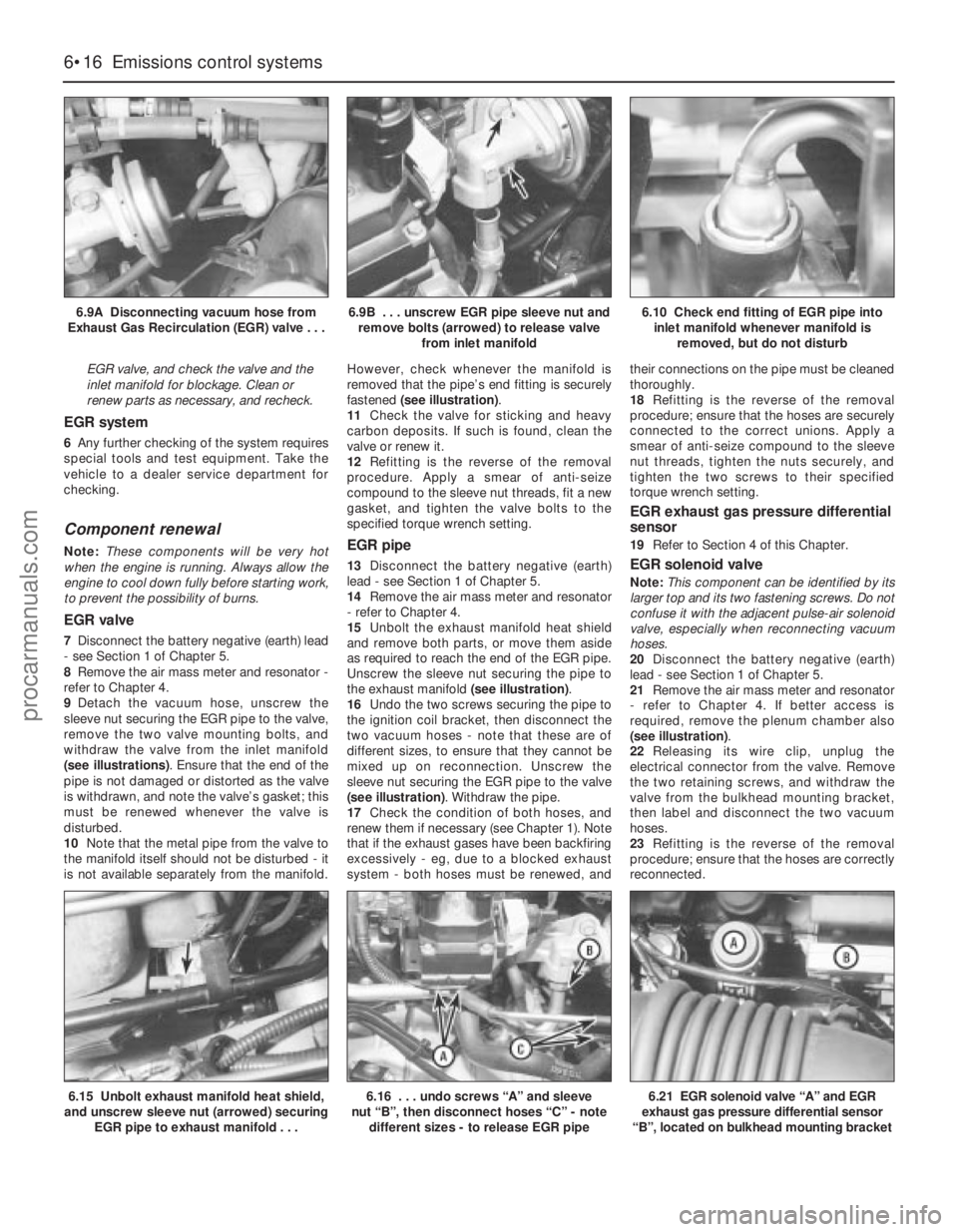
30 Cylinder No 3 low During cylinder balance test
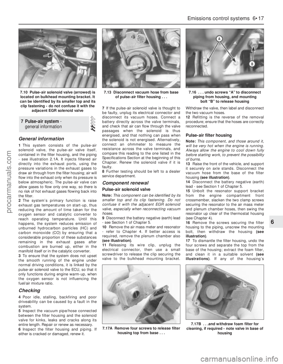
40 Cylinder No 4 low During cylinder balance test
90 Cylinder balance test successful -
111 No faults found -
112 to 114 Intake air temperature sensor Check component (Section 4 of this Chapter)116 to 118 Coolant temperature sensor - normal If fault still exists on reaching normal operating temperature, check
operating temperature not reached component (Chapter 3)
121 to 125 Throttle potentiometer Check component (Section 4 of this Chapter)129 Incorrect response from air mass
meter while conducting test Repeat test
136, 137 Oxygen sensor Check component (Section 4 of this Chapter)
139 Oxygen sensor Check component (Section 4 of this Chapter)
144 Oxygen sensor Check component (Section 4 of this Chapter)
157 to 159 Air mass meter Check component (Section 4 of this Chapter)
167 Incorrect response from throttle
potentiometer while conducting test Repeat test
171 Oxygen sensor Check component (Section 4 of this Chapter)
172 Oxygen sensor - mixture too weak Check component (Section 4 of this Chapter)
173 Oxygen sensor - mixture too rich Check component (Section 4 of this Chapter)
174, 175 Oxygen sensor Check component (Section 4 of this Chapter)
176 Oxygen sensor - mixture too weak Check component (Section 4 of this Chapter)
177 Oxygen sensor - mixture too rich Check component (Section 4 of this Chapter)
178 Oxygen sensor Check component (Section 4 of this Chapter)
179 Fuel system - mixture too weak Check EGR valve (Section 6 of this Chapter)
181 Fuel system - mixture too rich Check EGR valve (Section 6 of this Chapter)
182 Idle mixture too weak Check idle speed control valve (Chapter 4)
183 Idle mixture too rich If mixture OK, check fuel system (see below)
184, 185 Air mass meter Check component (Section 4 of this Chapter)
186 Injector opening time (pulse width) too long Carry out system test (see below)
187 Injector opening time (pulse width) too short Carry out system test (see below)
188 Oxygen sensor - mixture too weak Check component (Section 4 of this Chapter)
189 Oxygen sensor - mixture too rich Check component (Section 4 of this Chapter)191 Idle mixture too weak Check EGR valve (Section 6 of this Chapter) and idle speed control valve
(Chapter 4)
192 Idle mixture too rich Check EGR valve (Section 6 of this Chapter) and idle speed control valve
(Chapter 4)
194, 195 Oxygen sensor Check component (Section 4 of this Chapter)
211 No ignition signal to ECU Carry out system test (see below)
212 Tachometer circuit Carry out system test (see below)
213 No ignition signal from ECU Carry out system test (see below)
214 Camshaft position sensor Check component (Section 4 of this Chapter)
215 to 217 Ignition coil Carry out system test (see below)
218, 222 Tachometer circuit Carry out system test (see below)
226 ECU/ignition module pulse Carry out system test (see below)
227 Crankshaft speed/position sensor Check component (Chapter 5)
228 Ignition module/ignition coil winding 1 Carry out system test (see below)
229 Ignition module/ignition coil winding 2 Carry out system test (see below)
231 Ignition module/ignition coil winding 3 Carry out system test (see below)
232 Ignition coil primary windings Carry out system test (see below)
233 Ignition module Carry out system test (see below)
234 to 237 Ignition coil primary windings Carry out system test (see below)
238 Ignition module/ignition coil primary windings Carry out system test (see below)
239 No ignition signal to ECU on cranking Carry out system test (see below)
241 Incorrect response from ECU and/or
ignition module while conducting test Repeat test
243 Ignition coil failure Carry out system test (see below)
311 to 316 Pulse-air system Carry out system test (see below)326 EGR system exhaust gas pressure
differential sensor Check component (Section 6 of this Chapter)
procarmanuals.com
Page 144 of 279
Ignition timing and base idle
speed check
Note:The following procedure is a check only,
essentially of the ECU. Both the ignition timing
and the base idle speed are controlled by the
ECU. The ignition timing is not adjustable at
all; the base idle speed is set in production,
and should not be altered.
38If the fault code read-out (with any checks
resulting from it) has not eliminated the fault,
the next step is to check the ECU’s control of
the ignition timing and the base idle speed.
This task requires the use of a Ford STAR
tester (a proprietary fault code reader can be
used only if it is capable of inducing the ECU
to enter its “Service Adjustment Programme”),
coupled with an accurate tachometer and a
good-quality timing light. Without this
equipment, the task is not possible; the
vehicle must be taken to a Ford dealer for
attention.
39To make the check, apply the handbrake,
switch off the air conditioning (where fitted)
and any other electrical loads (lights, heated
rear window, etc), then select neutral (manual
transmission) or the “P” position (automatic
transmission). Start the engine, and warm it
up to normal operating temperature. The
radiator electric cooling fan must be running
continuously while the check is made; this
should be activated by the ECU, when
prompted by the tester. Switch off the engine,
and connect the test equipment as directed
by the manufacturer - refer to paragraph 26
above for details of STAR tester connection.
40Raise and support the front of the vehicle
securely, and remove the auxiliary drivebelt
cover (see Chapter 1). Emphasise the two
pairs of notches in the inner and outer rims of
the crankshaft pulley, using white paint. Note
that an ignition timing reference mark is not
provided on the pulley - in the normal
direction of crankshaft rotation (clockwise,
seen from the right-hand side of the vehicle)
the first pair of notches are irrelevant to the
vehicles covered in this manual, while the
second pair indicate Top Dead Centre (TDC)
when aligned with the rear edge of the raised
mark on the sump; when checking the ignition
timing, therefore, the (rear edge of the) sumpmark should appear just before the TDC
notches (see Part A of Chapter 2, Section 4,
for further information if required).
41Start the engine and allow it to idle. Work
through the engine-running test procedure
until the ECU enters its “Service Adjustment
Programme” - see paragraph 35 above.
42Use the timing light to check that the
timing marks appear approximately as
outlined above at idle speed. Do not spend
too much time on this check; if the timing
appears to be incorrect, the system may have
a fault, and a full system test must be carried
out (see below) to establish its cause.
43Using the tachometer, check that the
base idle speed is as given in the
Specifications Section of Chapter 4.
44If the recorded speed differs significantly
from the specified value, check for air leaks,
as described in the preliminary checks
(paragraphs 15 to 18 above), or any other
faults which might cause the discrepancy.
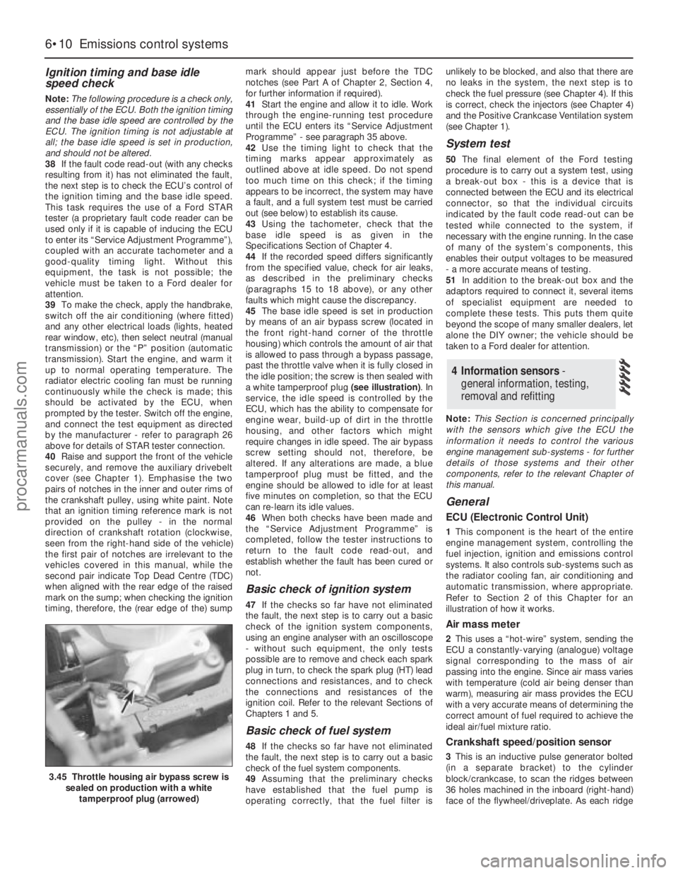
45The base idle speed is set in production
by means of an air bypass screw (located in
the front right-hand corner of the throttle
housing) which controls the amount of air that
is allowed to pass through a bypass passage,
past the throttle valve when it is fully closed in
the idle position; the screw is then sealed with
a white tamperproof plug (see illustration). In
service, the idle speed is controlled by the
ECU, which has the ability to compensate for
engine wear, build-up of dirt in the throttle
housing, and other factors which might
require changes in idle speed. The air bypass
screw setting should not, therefore, be
altered. If any alterations are made, a blue
tamperproof plug must be fitted, and the
engine should be allowed to idle for at least
five minutes on completion, so that the ECU
can re-learn its idle values.
46When both checks have been made and
the “Service Adjustment Programme” is
completed, follow the tester instructions to
return to the fault code read-out, and
establish whether the fault has been cured or
not.
Basic check of ignition system
47If the checks so far have not eliminated
the fault, the next step is to carry out a basic
check of the ignition system components,
using an engine analyser with an oscilloscope
- without such equipment, the only tests
possible are to remove and check each spark
plug in turn, to check the spark plug (HT) lead
connections and resistances, and to check
the connections and resistances of the
ignition coil. Refer to the relevant Sections of
Chapters 1 and 5.
Basic check of fuel system
48If the checks so far have not eliminated
the fault, the next step is to carry out a basic
check of the fuel system components.
49Assuming that the preliminary checks
have established that the fuel pump is
operating correctly, that the fuel filter isunlikely to be blocked, and also that there are
no leaks in the system, the next step is to
check the fuel pressure (see Chapter 4). If this
is correct, check the injectors (see Chapter 4)
and the Positive Crankcase Ventilation system
(see Chapter 1).
System test
50The final element of the Ford testing
procedure is to carry out a system test, using
a break-out box - this is a device that is
connected between the ECU and its electrical
connector, so that the individual circuits
indicated by the fault code read-out can be
tested while connected to the system, if
necessary with the engine running. In the case
of many of the system’s components, this
enables their output voltages to be measured
- a more accurate means of testing.
51In addition to the break-out box and the
adaptors required to connect it, several items
of specialist equipment are needed to
complete these tests. This puts them quite
beyond the scope of many smaller dealers, let
alone the DIY owner; the vehicle should be
taken to a Ford dealer for attention.
Note:This Section is concerned principally
with the sensors which give the ECU the
information it needs to control the various
engine management sub-systems - for further
details of those systems and their other
components, refer to the relevant Chapter of
this manual.
General
ECU (Electronic Control Unit)
1This component is the heart of the entire
engine management system, controlling the
fuel injection, ignition and emissions control
systems. It also controls sub-systems such as
the radiator cooling fan, air conditioning and
automatic transmission, where appropriate.
Refer to Section 2 of this Chapter for an
illustration of how it works.
Air mass meter
2This uses a “hot-wire” system, sending the
ECU a constantly-varying (analogue) voltage
signal corresponding to the mass of air
passing into the engine. Since air mass varies
with temperature (cold air being denser than
warm), measuring air mass provides the ECU
with a very accurate means of determining the
correct amount of fuel required to achieve the
ideal air/fuel mixture ratio.
Crankshaft speed/position sensor
3This is an inductive pulse generator bolted
(in a separate bracket) to the cylinder
block/crankcase, to scan the ridges between
36 holes machined in the inboard (right-hand)
face of the flywheel/driveplate. As each ridge
4 Information sensors -
general information, testing,
removal and refitting
6•10 Emissions control systems
3.45 Throttle housing air bypass screw is
sealed on production with a white
tamperproof plug (arrowed)
procarmanuals.com
Page 145 of 279
passes the sensor tip, a signal is generated,
which is used by the ECU to determine engine
speed.
4The ridge between the 35th and 36th holes
(corresponding to 90° BTDC) is missing - this
step in the incoming signals is used by the
ECU to determine crankshaft (ie, piston)
position.
Camshaft position sensor
5This is bolted to the rear left-hand end of
the cylinder head, to register with a lobe on
the inlet camshaft. It functions in the same
way as the crankshaft speed/position sensor,
producing a series of pulses (corresponding
to No 1 cylinder at 46° ATDC); this gives the
ECU a reference point, to enable it to
determine the firing order, and operate the
injectors in the appropriate sequence.
Coolant temperature sensor
6This component, which is screwed into the
top of the thermostat housing, is an NTC
(Negative Temperature Coefficient) thermistor
- that is, a semi-conductor whose electrical
resistance decreases as its temperature
increases. It provides the ECU with a
constantly-varying (analogue) voltage signal,
corresponding to the temperature of the
engine coolant. This is used to refine the
calculations made by the ECU, when
determining the correct amount of fuel
required to achieve the ideal air/fuel mixture
ratio.
Intake air temperature sensor
7This component, which is screwed into the
underside of the air intake resonator, is also an
NTC thermistor - see the previous paragraph -
providing the ECU with a signal corresponding
to the temperature of air passing into the
engine. This is used to refine the calculations
made by the ECU, when determining the
correct amount of fuel required to achieve the
ideal air/fuel mixture ratio.
Throttle potentiometer
8This is mounted on the end of the throttle
valve spindle, to provide the ECU with a
constantly-varying (analogue) voltage signal
corresponding to the throttle opening. This
allows the ECU to register the driver’s input
when determining the amount of fuel required
by the engine.
Vehicle speed sensor
9This component is a Hall-effect generator,
mounted on the transmission’s speedometer
drive. It supplies the ECU with a series of
pulses corresponding to the vehicle’s road
speed, enabling the ECU to control features
such as the fuel shut-off on the overrun, and
to provide information for the trip computer,
adaptive damping and cruise control systems
(where fitted).
Power steering pressure switch
10This is a pressure-operated switch,
screwed into the power steering system’shigh-pressure pipe. Its contacts are normally
closed, opening when the system reaches the
specified pressure - on receiving this signal,
the ECU increases the idle speed, to
compensate for the additional load on the
engine.
Exhaust gas pressure differential
sensor
11This component measures the difference
in pressure of the exhaust gases across a
venturi (restriction) in the Exhaust Gas
Recirculation (EGR) system’s pipe, and sends
the ECU a voltage signal corresponding to the
pressure difference.
Oxygen sensor
12The oxygen sensor in the exhaust system
provides the ECU with constant feedback -
“closed-loop” control - which enables it to
adjust the mixture to provide the best possible
conditions for the catalytic converter to
operate.
13The sensor has a built-in heating element
which is controlled by the ECU, in order to
bring the sensor’s tip to an efficient operating
temperature as rapidly as possible. The
sensor’s tip is sensitive to oxygen, and sends
the ECU a varying voltage depending on the
amount of oxygen in the exhaust gases. If the
intake air/fuel mixture is too rich, the exhaust
gases are low in oxygen, so the sensor sends
a low-voltage signal, the voltage rising as the
mixture weakens and the amount of oxygen in
the exhaust gases rises. Peak conversion
efficiency of all major pollutants occurs if the
intake air/fuel mixture is maintained at the
chemically-correct ratio for the complete
combustion of petrol, of 14.7 parts (by weight)
of air to 1 part of fuel (the “stoichiometric”
ratio). The sensor output voltage alters sharply
around this point, the ECU using the signal
change as a reference point, and correcting
the air/fuel mixture by altering the fuel injector
pulse width.
Air conditioning system
14Two pressure-operated switches and the
compressor clutch solenoid are connected to
the ECU, to enable it to determine how the
system is operating. The ECU can increase
idle speed or switch off the system, as
necessary, so that normal vehicle operation
and driveability are not impaired. See Chapter
3 for further details, but note that diagnosis
and repair should be left to a dealer service
department or air conditioning specialist.
Automatic transmission
15In addition to the driver’s controls, the
transmission has a speed sensor, a fluid
temperature sensor (built into the solenoid
valve unit), and a selector lever position
sensor. All of these are connected to the ECU,
to enable it to control the transmission
through the solenoid valve unit. See Part B of
Chapter 7 for further details.
Testing
ECU (Electronic Control Unit)
16 Do notattempt to “test” the ECU with any
kind of equipment. If it is thought to be faulty,
take the vehicle to a Ford dealer for the entire
electronic control system to be checked using
the proper diagnostic equipment. Only if all
other possibilities have been eliminated should
the ECU be considered at fault, and replaced.
Air mass meter
17Testing of this component is beyond the
scope of the DIY mechanic, and should be left
to a Ford dealer.
Crankshaft speed/position sensor
18Unplug the electrical connector from the
sensor.
19Using an ohmmeter, measure the
resistance between the sensor terminals.
Compare this reading to the one listed in the
Specifications Section at the beginning of this
Chapter. If the indicated resistance is not
within the specified range, renew the sensor.
20Plug in the sensor’s electrical connector
on completion.
Camshaft position sensor
21The procedure is as described in
paragraphs 18 to 20 above.
Coolant temperature sensor
22Refer to Chapter 3.
Intake air temperature sensor
23Unplug the electrical connector from the
sensor.
24Using an ohmmeter, measure the
resistance between the sensor terminals.
Depending on the temperature of the sensor
tip, the resistance measured will vary, but it
should be within the broad limits given in the
Specifications Section of this Chapter. If the
sensor’s temperature is varied - by placing it
in a freezer for a while, or by warming it gently
- its resistance should alter accordingly.
25If the results obtained show the sensor to
be faulty, renew it.
Throttle potentiometer
26Remove the plenum chamber (see
Chapter 4) and unplug the potentiometer’s
electrical connector.
27Using an ohmmeter, measure the
resistance between the unit’s terminals - first
between the centre terminal and one of the
outer two, then from the centre to the
remaining outer terminal. The resistance
should be within the limits given in the
Specifications Section of this Chapter, and
should alter smoothlyas the throttle valve is
moved from the fully-closed (idle speed)
position to fully open and back again.
28If the resistance measured is significantly
different from the specified value, if there are
any breaks in continuity, or if the reading
fluctuates erratically as the throttle is
operated, the potentiometer is faulty, and
must be renewed.
Emissions control systems 6•11
6
procarmanuals.com
Page 149 of 279
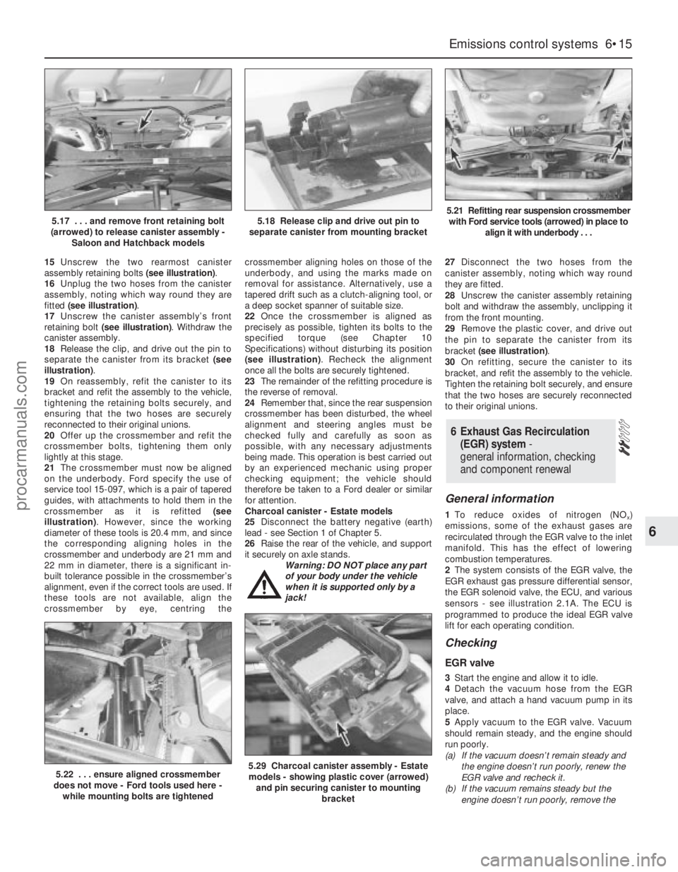
15Unscrew the two rearmost canister
assembly retaining bolts (see illustration).
16Unplug the two hoses from the canister
assembly, noting which way round they are
fitted (see illustration).
17Unscrew the canister assembly’s front
retaining bolt (see illustration). Withdraw the
canister assembly.
18Release the clip, and drive out the pin to
separate the canister from its bracket (see
illustration).
19On reassembly, refit the canister to its
bracket and refit the assembly to the vehicle,
tightening the retaining bolts securely, and
ensuring that the two hoses are securely
reconnected to their original unions.
20Offer up the crossmember and refit the
crossmember bolts, tightening them only
lightly at this stage.
21The crossmember must now be aligned
on the underbody. Ford specify the use of
service tool 15-097, which is a pair of tapered
guides, with attachments to hold them in the
crossmember as it is refitted (see
illustration). However, since the working
diameter of these tools is 20.4 mm, and since
the corresponding aligning holes in the
crossmember and underbody are 21 mm and
22 mm in diameter, there is a significant in-
built tolerance possible in the crossmember’s
alignment, even if the correct tools are used. If
these tools are not available, align the
crossmember by eye, centring thecrossmember aligning holes on those of the
underbody, and using the marks made on
removal for assistance. Alternatively, use a
tapered drift such as a clutch-aligning tool, or
a deep socket spanner of suitable size.
22Once the crossmember is aligned as
precisely as possible, tighten its bolts to the
specified torque (see Chapter 10
Specifications) without disturbing its position
(see illustration). Recheck the alignment
once all the bolts are securely tightened.
23The remainder of the refitting procedure is
the reverse of removal.
24Remember that, since the rear suspension
crossmember has been disturbed, the wheel
alignment and steering angles must be
checked fully and carefully as soon as
possible, with any necessary adjustments
being made. This operation is best carried out
by an experienced mechanic using proper
checking equipment; the vehicle should
therefore be taken to a Ford dealer or similar
for attention.
Charcoal canister - Estate models
25Disconnect the battery negative (earth)
lead - see Section 1 of Chapter 5.
26Raise the rear of the vehicle, and support
it securely on axle stands.
Warning: DO NOT place any part
of your body under the vehicle
when it is supported only by a
jack!27Disconnect the two hoses from the
canister assembly, noting which way round
they are fitted.
28Unscrew the canister assembly retaining
bolt and withdraw the assembly, unclipping it
from the front mounting.
29Remove the plastic cover, and drive out
the pin to separate the canister from its
bracket (see illustration).
30On refitting, secure the canister to its
bracket, and refit the assembly to the vehicle.
Tighten the retaining bolt securely, and ensure
that the two hoses are securely reconnected
to their original unions.
General information
1To reduce oxides of nitrogen (NOx)
emissions, some of the exhaust gases are
recirculated through the EGR valve to the inlet
manifold. This has the effect of lowering
combustion temperatures.
2The system consists of the EGR valve, the
EGR exhaust gas pressure differential sensor,
the EGR solenoid valve, the ECU, and various
sensors - see illustration 2.1A. The ECU is
programmed to produce the ideal EGR valve
lift for each operating condition.
Checking
EGR valve
3Start the engine and allow it to idle.
4Detach the vacuum hose from the EGR
valve, and attach a hand vacuum pump in its
place.
5Apply vacuum to the EGR valve. Vacuum
should remain steady, and the engine should
run poorly.
(a) If the vacuum doesn’t remain steady and
the engine doesn’t run poorly, renew the
EGR valve and recheck it.
(b) If the vacuum remains steady but the
engine doesn’t run poorly, remove the
6 Exhaust Gas Recirculation
(EGR) system-
general information, checking
and component renewal
Emissions control systems 6•15
6
5.22 . . . ensure aligned crossmember
does not move - Ford tools used here -
while mounting bolts are tightened5.29 Charcoal canister assembly - Estate
models - showing plastic cover (arrowed)
and pin securing canister to mounting
bracket
5.17 . . . and remove front retaining bolt
(arrowed) to release canister assembly -
Saloon and Hatchback models5.18 Release clip and drive out pin to
separate canister from mounting bracket5.21 Refitting rear suspension crossmember
with Ford service tools (arrowed) in place to
align it with underbody . . .
procarmanuals.com
Page 150 of 279
EGR valve, and check the valve and the
inlet manifold for blockage. Clean or
renew parts as necessary, and recheck.
EGR system
6Any further checking of the system requires
special tools and test equipment. Take the
vehicle to a dealer service department for
checking.
Component renewal
Note:These components will be very hot
when the engine is running. Always allow the
engine to cool down fully before starting work,
to prevent the possibility of burns.
EGR valve
7Disconnect the battery negative (earth) lead
- see Section 1 of Chapter 5.
8Remove the air mass meter and resonator -
refer to Chapter 4.
9Detach the vacuum hose, unscrew the
sleeve nut securing the EGR pipe to the valve,
remove the two valve mounting bolts, and
withdraw the valve from the inlet manifold
(see illustrations). Ensure that the end of the
pipe is not damaged or distorted as the valve
is withdrawn, and note the valve’s gasket; this
must be renewed whenever the valve is
disturbed.
10Note that the metal pipe from the valve to
the manifold itself should not be disturbed - it
is not available separately from the manifold.However, check whenever the manifold is
removed that the pipe’s end fitting is securely
fastened (see illustration).
11Check the valve for sticking and heavy
carbon deposits. If such is found, clean the
valve or renew it.
12Refitting is the reverse of the removal
procedure. Apply a smear of anti-seize
compound to the sleeve nut threads, fit a new
gasket, and tighten the valve bolts to the
specified torque wrench setting.
EGR pipe
13Disconnect the battery negative (earth)
lead - see Section 1 of Chapter 5.
14Remove the air mass meter and resonator
- refer to Chapter 4.
15Unbolt the exhaust manifold heat shield
and remove both parts, or move them aside
as required to reach the end of the EGR pipe.
Unscrew the sleeve nut securing the pipe to
the exhaust manifold (see illustration).
16Undo the two screws securing the pipe to
the ignition coil bracket, then disconnect the
two vacuum hoses - note that these are of
different sizes, to ensure that they cannot be
mixed up on reconnection. Unscrew the
sleeve nut securing the EGR pipe to the valve
(see illustration). Withdraw the pipe.
17Check the condition of both hoses, and
renew them if necessary (see Chapter 1). Note
that if the exhaust gases have been backfiring
excessively - eg, due to a blocked exhaust
system - both hoses must be renewed, andtheir connections on the pipe must be cleaned
thoroughly.
18Refitting is the reverse of the removal
procedure; ensure that the hoses are securely
connected to the correct unions. Apply a
smear of anti-seize compound to the sleeve
nut threads, tighten the nuts securely, and
tighten the two screws to their specified
torque wrench setting.
EGR exhaust gas pressure differential
sensor
19Refer to Section 4 of this Chapter.
EGR solenoid valve
Note:This component can be identified by its
larger top and its two fastening screws. Do not
confuse it with the adjacent pulse-air solenoid
valve, especially when reconnecting vacuum
hoses.
20Disconnect the battery negative (earth)
lead - see Section 1 of Chapter 5.
21Remove the air mass meter and resonator
- refer to Chapter 4. If better access is
required, remove the plenum chamber also
(see illustration).
22Releasing its wire clip, unplug the
electrical connector from the valve. Remove
the two retaining screws, and withdraw the
valve from the bulkhead mounting bracket,
then label and disconnect the two vacuum
hoses.
23Refitting is the reverse of the removal
procedure; ensure that the hoses are correctly
reconnected.
6•16 Emissions control systems
6.9A Disconnecting vacuum hose from
Exhaust Gas Recirculation (EGR) valve . . .6.9B . . . unscrew EGR pipe sleeve nut and
remove bolts (arrowed) to release valve
from inlet manifold6.10 Check end fitting of EGR pipe into
inlet manifold whenever manifold is
removed, but do not disturb
6.15 Unbolt exhaust manifold heat shield,
and unscrew sleeve nut (arrowed) securing
EGR pipe to exhaust manifold . . .6.16 . . . undo screws “A” and sleeve
nut “B”, then disconnect hoses “C” - note
different sizes - to release EGR pipe6.21 EGR solenoid valve “A” and EGR
exhaust gas pressure differential sensor
“B”, located on bulkhead mounting bracket
procarmanuals.com
Page 151 of 279
General information
1This system consists of the pulse-air
solenoid valve, the pulse-air valve itself,
contained in the filter housing, and the piping
- see illustration 2.1A. It injects filtered air
directly into the exhaust ports, using the
pressure variations in the exhaust gases to
draw air through from the filter housing; air will
flow into the exhaust only when its pressure is
below atmospheric. The pulse-air valve can
allow gases to flow only one way, so there is
no risk of hot exhaust gases flowing back into
the filter.
2The system’s primary function is raise
exhaust gas temperatures on start-up, thus
reducing the amount of time taken for the
oxygen sensor and catalytic converter to
reach operating temperature. Until this
happens, the system reduces emission of
unburned hydrocarbon particles (HC) and
carbon monoxide (CO) by ensuring that a
considerable proportion of these substances
remaining in the exhaust gases after
combustion are burned up, either in the
manifold itself or in the catalytic converter.
3To ensure that the system does not upset
the smooth running of the engine under
normal driving conditions, it is linked by the
pulse-air solenoid valve to the ECU, so that it
only functions during engine warm-up, when
the oxygen sensor is not influencing the
fuel/air mixture ratio.
Checking
4Poor idle, stalling, backfiring and poor
driveability can be caused by a fault in the
system.
5Inspect the vacuum pipe/hose connected
between the filter housing and the solenoid
valve for kinks, leaks and cracks along its
entire length. Repair or renew as necessary.
6Inspect the filter housing and piping. If
either is cracked or damaged, renew it.7If the pulse-air solenoid valve is thought to
be faulty, unplug its electrical connector and
disconnect its vacuum hoses. Connect a
battery directly across the valve terminals,
and check that air can flow through the valve
passages when the solenoid is thus
energised, and that nothing can pass when
the solenoid is not energised. Alternatively,
connect an ohmmeter to measure the
resistance across the valve terminals, and
compare this reading to the one listed in the
Specifications Section at the beginning of this
Chapter. Renew the solenoid valve if it is
faulty.
8Further testing should be left to a dealer
service department.
Component renewal
Pulse-air solenoid valve
Note:This component can be identified by its
smaller top and its clip fastening. Do not
confuse it with the adjacent EGR solenoid
valve, especially when reconnecting vacuum
hoses.
9Disconnect the battery negative (earth) lead
- see Section 1 of Chapter 5.
10Remove the air mass meter and resonator
- refer to Chapter 4. If better access is
required, remove the plenum chamber also
(see illustration).
11Releasing its wire clip, unplug the
electrical connector, then use a small
screwdriver to release the clip securing the
valve to the bulkhead mounting bracket.Withdraw the valve, then label and disconnect
the two vacuum hoses.
12Refitting is the reverse of the removal
procedure; ensure that the hoses are correctly
reconnected.
Pulse-air filter housing
Note:This component, and those around it,
will be very hot when the engine is running.
Always allow the engine to cool down fully
before starting work, to prevent the possibility
of burns.
13Raise the front of the vehicle, and support
it securely on axle stands. Disconnect the
vacuum hose from the base of the filter
housing (see illustration).
14Disconnect the battery negative (earth)
lead - see Section 1 of Chapter 5.
15Unbolt the resonator support bracket
from the engine compartment front
crossmember, slacken the two clamp screws
securing the resonator to the air mass meter
and plenum chamber hoses, then swing the
resonator up clear of the thermostat housing
(see Chapter 4).
16Remove the screws securing the filter
housing to the piping, unscrew the mounting
bolt, then withdraw the housing (see
illustration).
17To dismantle the filter housing, undo the
four screws and separate the top from the
base of the housing; extract the foam filter,
and clean it in a suitable solvent (see
illustrations). If any of the housing’s
7 Pulse-air system -
general information
Emissions control systems 6•17
6
7.17A Remove four screws to release filter
housing top from base . . .7.17B . . .and withdraw foam filter for
cleaning, if required - note valve in base of
housing
7.10 Pulse-air solenoid valve (arrowed) is
located on bulkhead mounting bracket. It
can be identified by its smaller top and its
clip fastening - do not confuse it with the
adjacent EGR solenoid valve7.13 Disconnect vacuum hose from base
of pulse-air filter housing . . .7.16 . . . undo screws “A” to disconnect
piping from housing, and mounting
bolt “B” to release housing
procarmanuals.com
Page 153 of 279
2The function of these components is to
reduce the emission of unburned
hydrocarbons from the crankcase, and to
minimise the formation of oil sludge. By
ensuring that a depression is created in the
crankcase under most operating conditions,
particularly at idle, and by positively inducing
fresh air into the system, the oil vapours and
“blow-by” gases collected in the crankcase
are drawn from the crankcase, through the oil
separator, into the inlet tract, to be burned by
the engine during normal combustion.
Checking
3Checking procedures for the system
components are included in Chapter 1.
Component renewal
Cylinder head-to-air cleaner hose
4See Chapter 1.
Positive Crankcase Ventilation (PCV)
valve
5The valve is plugged into the oil separator.
Depending on the tools available, access to
the valve may be possible once the pulse-air
assembly has been removed (see Section 7).
If this is not feasible, proceed as outlined in
paragraph 6 below.
Oil separator
6Remove the exhaust manifold (see Chap-
ter 2, Part A). The Positive Crankcase
Ventilation (PCV) valve can now be unplugged
and flushed, or renewed, as required, as
described in Chapter 1.
7Unbolt the oil separator from the cylinder
block/crankcase, and withdraw it; remove and
discard the gasket.
8Flush out or renew the oil separator, as
required (see Chapter 1).
9On reassembly, fit a new gasket, and
tighten the fasteners to the torque wrench
settings given in the Specifications Section of
Chapter 2, Part B.
10The remainder of the refitting procedure is
the reverse of removal. Refill the cooling
system (see Chapter 1). Run the engine,
check for exhaust leaks, and check the
coolant level when it is fully warmed-up.
General information
1The exhaust gases of any petrol engine
(however efficient or well-tuned) consist
largely (approximately 99 %) of nitrogen (N
2),
carbon dioxide (CO
2), oxygen (O2), other inert
gases and water vapour (H
2O). The remaining
1 % is made up of the noxious materials
which are currently seen (CO
2apart) as the
major polluters of the environment: carbon
monoxide (CO), unburned hydrocarbons (HC),oxides of nitrogen (NO
x) and some solid
matter, including a small lead content.
2Left to themselves, most of these pollutants
are thought eventually to break down naturally
(CO and NO
x, for example, break down in the
upper atmosphere to release CO
2) having first
caused ground-level environmental problems.
The massive increase world-wide in the use of
motor vehicles, and the current popular
concern for the environment has caused the
introduction in most countries of legislation, in
varying degrees of severity, to combat the
problem.
3The device most commonly used to clean
up vehicle exhausts is the catalytic converter.
It is fitted into the vehicle’s exhaust system,
and uses precious metals (platinum and
palladium or rhodium) as catalysts to speed
up the reaction between the pollutants and
the oxygen in the vehicle’s exhaust gases, CO
and HC being oxidised to form H
2O and CO2and (in the three-way type of catalytic
converter) NO
xbeing reduced to N2. Note:
The catalytic converter is not a filter in the
physical sense; its function is to promote a
chemical reaction, but it is not itself affected
by that reaction.
4The converter consists of an element (or
“substrate”) of ceramic honeycomb, coated
with a combination of precious metals in such
a way as to produce a vast surface area over
which the exhaust gases must flow; the whole
being mounted in a stainless-steel box. A
simple “oxidation” (or “two-way”) catalytic
converter can deal with CO and HC only,
while a “reduction” (or “three-way”) catalytic
converter can deal with CO, HC and NO
x.
Three-way catalytic converters are further
sub-divided into “open-loop” (or
“uncontrolled”) converters which can remove
50 to 70 % of pollutants and “closed-loop”
(also known as “controlled” or “regulated”)
converters which can remove over 90 % of
pollutants.
5The catalytic converter fitted to the Mondeo
models covered in this manual is of the three-
way closed-loop type.
6The catalytic converter is a reliable and
simple device, which needs no maintenance
in itself, but there are some facts of which an
owner should be aware if the converter is to
function properly for its full service life.
(a) DO NOT use leaded petrol in a vehicle
equipped with a catalytic converter - the
lead will coat the precious metals,
reducing their converting efficiency, and
will eventually destroy the converter; it will
also affect the operation of the oxygen
sensor, requiring its renewal if lead-
fouled. Opinions vary as to how much
leaded fuel is necessary to affect the
converter’s performance, and whether it
can recover even if only unleaded petrol is
used afterwards; the best course of action
is, therefore, to assume the worst, and to
ensure that NO leaded petrol is used at
any time.
(b) Always keep the ignition and fuel systemswell-maintained in accordance with the
manufacturer’s schedule (Chapter 1) -
particularly, ensure that the air filter
element, the fuel filter and the spark plugs
are renewed at the correct intervals. If the
intake air/fuel mixture is allowed to
become too rich due to neglect, the
unburned surplus will enter and burn in
the catalytic converter, overheating the
element and eventually destroying the
converter.
(c) If the engine develops a misfire, do not
drive the vehicle at all (or at least as little
as possible) until the fault is cured - the
misfire will allow unburned fuel to enter
the converter, which will result in its
overheating, as noted above. For the
same reason, do not persist if the engine
refuses to start - either trace the problem
and cure it yourself, or have the vehicle
checked immediately by a qualified
mechanic.
(d) Avoid allowing the vehicle to run out of
petrol.
(e) DO NOT push- or tow-start the vehicle
unless no other alternative exists,
especially if the engine and exhaust are at
normal operating temperature. Starting
the engine in this way may soak the
catalytic converter in unburned fuel,
causing it to overheat when the engine
does start - see (b) above.
(f) DO NOT switch off the ignition at high
engine speeds, in particular, do not “blip”
the throttle immediately before switching
off. If the ignition is switched off at
anything above idle speed, unburned fuel
will enter the (very hot) catalytic converter,
with the possible risk of its igniting on the
element and damaging the converter.
(g) Avoid repeated successive cold starts
followed by short journeys. If the
converter is never allowed to reach its
proper working temperature, it will gather
unburned fuel, allowing some to pass into
the atmosphere and the rest to soak in
the element, causing it to overheat when
a long journey is made - see (b) above.
(h) DO NOT use fuel or engine oil additives -
these may contain substances harmful to
the catalytic converter. Similarly, DO NOT
use silicone-based sealants on any part of
the engine or fuel system, and do not use
exhaust sealants on any part of the
exhaust system upstream of the catalytic
converter. Even if the sealant itself does
not contain additives harmful to the
converter, pieces of it may break off and
foul the element, causing local
overheating.
(i) DO NOT continue to use the vehicle if the
engine burns oil to the extent of leaving a
visible trail of blue smoke. Unburned
carbon deposits will clog the converter
passages and reduce its efficiency; in
severe cases, the element will overheat.
(j) Remember that the catalytic converter
operates at very high temperatures -
9 Catalytic converter -
general information, checking
and component renewal
Emissions control systems 6•19
6
procarmanuals.com
Page 159 of 279
Since most of the procedures dealt with in
this Chapter involve jacking up the vehicle
and working underneath it, a good pair of axle
stands will be needed. A hydraulic trolley jack
is the preferred type of jack to lift the vehicle,
and it can also be used to support certain
components during removal and refitting
operations.
Warning: Never, under any
circumstances, rely on a jack to
support the vehicle while working
beneath it. When jacking up the vehicle, do
not lift or support it beneath the front or
rear subframes.
Removal
1Apply the handbrake. Remove the wheel
cover from the relevant front wheel, and
loosen (but do not remove) the driveshaft/hub
nut. This nut is very tight.
2Loosen the front wheel nuts, jack up the
front of the vehicle and support it on axle
stands. Remove the front wheel.
3Extract the split pin from the track rod end
balljoint nut. Unscrew the nut, and detach the
rod from the arm on the steering knuckle
using a conventional balljoint removal tool.
Take care not to damage the balljoint seal.
4Remove the ABS sensor (when fitted) as
described in Chapter 9.
5Remove the brake caliper and brake disc as
described in Chapter 9, but do not disconnect
the flexible hose from the caliper. Suspend
the caliper from a suitable point under the
wheel arch, taking care not to strain the hose.
6Unscrew and remove the driveshaft/hub
nut. Note that the nut is of special laminated
design, and should only be re-used a
maximum of 5 times. (It is a good idea to file a
small notch on the nut every time it is
removed.) Obtain a new nut if necessary.
7Note which way round the lower arm
balljoint clamp bolt is fitted, then unscrew and
remove it from the knuckle assembly. Lever
the balljoint down from the knuckle; if it is
tight, prise the clamp open using a large flat-
bladed tool. Take care not to damage the
balljoint seal during the separation procedure.
8Unscrew and remove the pinch-bolt
securing the steering knuckle assembly to the
front suspension strut, noting which way
round it is fitted. Prise open the clamp using a
wedge-shaped tool, and release the knuckle
from the strut. If necessary, tap the knuckle
downwards with a soft-headed mallet to
separate the two components. Support the
knuckle on an axle stand.
9Pull the steering knuckle and hub assembly
from the driveshaft splines. If it is tight,
connect a universal puller to the hub flange,
and withdraw it from the driveshaft. When the
driveshaft is free, support it on an axle stand,
or suspend it from a suitable point under thewheel arch, making sure that the inner
constant velocity joint is not turned through
more than 18°. (Damage may occur if the joint
is turned through too great an angle.)
Refitting
10Lift the steering knuckle and hub
assembly onto the driveshaft splines, and
support the assembly on an axle stand.
11Locate the assembly on the front
suspension strut. Insert the pinch-bolt with its
head facing forwards. Fit the nut and tighten it
to the specified torque.
12Refit the lower arm balljoint to the knuckle
assembly, and insert the clamp bolt with its
head facing forwards. Refit the nut and tighten
it to the specified torque.
13Refit the driveshaft/hub nut, and tighten it
moderately at this stage. Final tightening of
the nut is made with the vehicle lowered to the
ground.
14Refit the brake caliper and brake disc as
described in Chapter 9.
15Where fitted, refit the ABS sensor as
described in Chapter 9.
16Reconnect the track rod end balljoint to
the steering arm, and tighten the nut to the
specified torque. Check that the split pin
holes are aligned; if necessary, turn the nut to
the nearest alignment, making sure that the
torque wrench setting is still within the
specified range. Insert a new split pin, and
bend it back to secure.
17Refit the front wheel, and lower the
vehicle to the ground. Tighten the wheel nuts
to the specified torque.
18Tighten the driveshaft/hub nut to the
specified torque, and refit the wheel cover.
Inspection
1The front hub bearings are non-adjustable,
and are supplied already greased.
2To check the bearings for excessive wear,
apply the handbrake, jack up the front of the
vehicle and support it on axle stands.
3Grip the front wheel at top and bottom, and
attempt to rock it. If excessive movement is
noted, it may be that the hub bearings are
worn. Do not confuse wear in the driveshaft
outer joint or front suspension lower arm
balljoint with wear in the bearings. Hub
bearing wear will show up as roughness or
vibration when the wheel is spun; it will also
be noticeable as a rumbling or growling noise
when driving.
Renewal
4Remove the steering knuckle and hub
assembly as described in Section 2.
5The hub must now be removed from the
bearing inner races. It is preferable to use a
press to do this, but it is possible to drive outthe hub using a length of metal tube of
suitable diameter (see illustration).
6Part of the inner race will remain on the hub,
and this should be removed using a puller.
7Note that if this procedure is being used to
renew the hub only (ie it is not intended to
renew the bearings), then it is important to
check the condition of the bearing balls and
races, to see if they are fit for re-use. It is
difficult to be sure that no damage has
occurred, especially if makeshift methods
have been used during removal; in practice, it
is probably false economy not to renew the
bearings in any case, having got this far.
8Using circlip pliers, extract the inner and
outer circlips securing the hub bearing in the
steering knuckle (see illustration).
9Press or drive out the bearing, using a
length of metal tubing of diameter slightly less
than the bearing outer race.
10Clean the bearing seating faces in the
steering knuckle.
3 Front hub and bearings -
inspection and renewal
2 Steering knuckle and hub
assembly -
removal and refitting
Suspension and steering systems 10•5
10
3.5 Front hub and bearing
1 Hub 4 Stub axle
2 Double-row ball-bearing 5 Steering knuckle
3 Circlips 6 ABS sensor
3.8 Front wheel bearing retaining circlips
(arrowed)
procarmanuals.com