1993 FORD MONDEO fuel cap
[x] Cancel search: fuel capPage 117 of 279
starter motor must be overhauled or renewed.
(Other possibilities are that the starter motor
mounting bolts are very loose, or that teeth
are missing from the flywheel/driveplate ring
gear.)
4If, when the switch is actuated, the starter
motor does not operate at all but the solenoid
clicks, then the problem lies with either the
battery, the main solenoid contacts, or the
starter motor itself (or the engine is seized).
5If the solenoid plunger cannot be heard to
click when the switch is actuated, the battery
is faulty, there is a fault in the circuit, or the
solenoid itself is defective.
6To check the solenoid, connect a fused
jumper lead between the battery (+) and the
ignition switch terminal (the small terminal) on
the solenoid. If the starter motor now
operates, the solenoid is OK, and the problem
is in the ignition switch, selector lever position
sensor (automatic transmission) or in the
wiring.
7If the starter motor still does not operate,
remove it (see Section 16). The brushes and
commutator may be checked (see Sec-
tion 17), but if the fault persists, the motor
should be renewed, or taken to an auto-
electrician for testing and repair.
8If the starter motor cranks the engine at anabnormally-slow speed, first make sure that
the battery is charged, and that all terminal
connections are tight. If the engine is partially
seized, or has the wrong viscosity oil in it, it
will crank slowly.
9Run the engine until normal operating
temperature is reached, then switch off and
disable the ignition system by unplugging the
ignition coil’s electrical connector; remove
fuse 14 to disconnect the fuel pump.
10Connect a voltmeter positive lead to the
battery positive terminal, and connect the
negative lead to the negative terminal.
11Crank the engine, and take the voltmeter
readings as soon as a steady figure is
indicated. Do not allow the starter motor to
turn for more than 15 seconds at a time. A
reading of 10.5 volts or more, with the starter
motor turning at normal cranking speed, is
normal. If the reading is 10.5 volts or more but
the cranking speed is slow, the solenoid
contacts are burned, the motor is faulty, or
there is a bad connection. If the reading is less
than 10.5 volts and the cranking speed is
slow, the starter motor is faulty or there is a
problem with the battery.1Disconnect the battery negative (earth) lead
- see Section 1.
2Remove the air mass meter and resonator -
refer to Chapter 4.
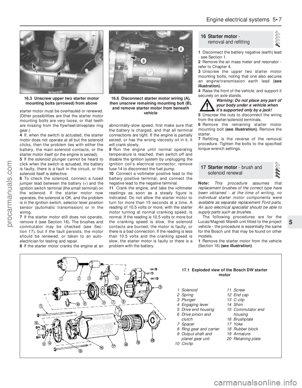
3Unscrew the upper two starter motor
mounting bolts, noting that one also secures
an engine/transmission earth lead (see
illustration).
4Raise the front of the vehicle, and support it
securely on axle stands.
Warning: Do not place any part of
your body under a vehicle when
it’s supported only by a jack!
5Unscrew the nuts to disconnect the wiring
from the starter/solenoid terminals.
6Remove the remaining starter motor
mounting bolt (see illustration). Remove the
starter.
7Refitting is the reverse of the removal
procedure. Tighten the bolts to the specified
torque wrench settings.
Note:This procedure assumes that
replacement brushes of the correct type have
been obtained - at the time of writing, no
individual starter motor components were
available as separate replacement Ford parts.
An auto electrical specialist should be able to
supply parts such as brushes.
The following procedures are for the
Lucas/Magneti Marelli unit fitted to the project
vehicle - the procedure is essentially the same
for the Bosch unit that may be found on other
models.
1Remove the starter motor from the vehicle
(Section 16) (see illustration).
17 Starter motor- brush and
solenoid renewal
16 Starter motor -
removal and refitting
Engine electrical systems 5•7
5
16.3 Unscrew upper two starter motor
mounting bolts (arrowed) from above16.6 Disconnect starter motor wiring (A),
then unscrew remaining mounting bolt (B),
and remove starter motor from beneath
vehicle
17.1 Exploded view of the Bosch DW starter
motor
1 Solenoid
2 Spring
3 Plunger
4 Engaging lever
5 Drive end housing
6 Drive pinion and
clutch
7 Spacer
8 Ring gear and carrier
9 Output shaft and
planet gear unit
10 Circlip11 Screw
12 End cap
13 C-clip
14 Shim
15 Commutator end
housing
16 Brushplate
17 Yoke
18 Rubber block
19 Armature
20 Retaining plate
procarmanuals.com
Page 140 of 279
back again, as an assistant depresses the
accelerator pedal. If the valve shows any sign
of stiffness, sticking or otherwise-inhibited
movement (and the accelerator cable is
known from the previous check to be in good
condition), spray the throttle linkage with
penetrating lubricant, allow time for it to work,
and repeat the check; if no improvement is
obtained, the complete throttle housing must
be renewed (Chapter 4).
15Unclip the air cleaner cover, and check
that the air filter element and the crankcase
ventilation system filter are not clogged or
soaked. (A clogged air filter will obstruct the
intake air flow, causing a noticeable effect on
engine performance; a clogged crankcase
ventilation system filter will inhibit crankcase
“breathing”). Renew or clean the filter(s) as
appropriate; refer to the relevant Sections of
Chapter 1 for further information, if required.
Before refitting the air cleaner cover, check
that the air intake (located under the front left-
hand wing, opening behind the direction
indicator/headlight assembly) is clear. It
should be possible to blow through the intake,
or to probe it (carefully) as far as the rear of
the direction indicator light.
16Start the engine and allow it to idle.
Note:Working in the engine compartment
while the engine is running requires great care
if the risk of personal injury is to be avoided;
among the dangers are burns from contact
with hot components, or contact with moving
components such as the radiator cooling fan
or the auxiliary drivebelt. Refer to “Safety
first!” at the front of this manual before
starting, and ensure that your hands, and long
hair or loose clothing, are kept well clear of hot
or moving components at all times.
17Working from the air intake junction at the
inner wing panel, via the air cleaner assembly
and air mass meter, to the resonator, plenum
chamber, throttle housing and inlet manifold
(and including the various vacuum hoses and
pipes connected to these), check for air leaks.
Usually, these will be revealed by sucking or
hissing noises, but minor leaks may be traced
by spraying a solution of soapy water on to
the suspect joint; if a leak exists, it will be
shown by the change in engine note and the
accompanying air bubbles (or sucking-in of
the liquid, depending on the pressure
difference at that point). If a leak is found at
any point, tighten the fastening clamp and/or
renew the faulty components, as applicable.
18Similarly, work from the cylinder head, via
the manifold (and not forgetting the related
EGR and pulse-air system components) to the
tailpipe, to check that the exhaust system is
free from leaks. The simplest way of doing
this, if the vehicle can be raised and
supported safely and with complete security
while the check is made, is to temporarily
block the tailpipe while listening for the sound
of escaping exhaust gases; any leak should
be evident. If a leak is found at any point,
tighten the fastening clamp bolts and/or nuts,
renew the gasket, and/or renew the faultysection of the system, as necessary, to seal
the leak.
19It is possible to make a further check of
the electrical connections by wiggling each
electrical connector of the system in turn as
the engine is idling; a faulty connector will be
immediately evident from the engine’s
response as contact is broken and remade. A
faulty connector should be renewed to ensure
the future reliability of the system; note that
this may mean the renewal of that entire
section of the loom - see your local Ford
dealer for details.
20Switch off the engine. If the fault is not yet
identified, the next step is to check the
ignition voltages, using an engine analyser
with an oscilloscope - without such
equipment, the only tests possible are to
remove and check each spark plug in turn, to
check the spark plug (HT) lead connections
and resistances, and to check the
connections and resistances of the ignition
coil. Refer to the relevant Sections of
Chapters 1 and 5.
21The final step in these preliminary checks
would be to use an exhaust gas analyser to
measure the CO level at the exhaust tailpipe.This check cannot be made without special
test equipment - see your local Ford dealer for
details.
Fault code read-out
22As noted in the general comments at the
beginning of this Section, the preliminary
checks outlined above should eliminate the
majority of faults from the engine
management system. If the fault is not yet
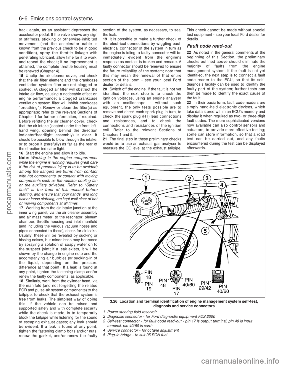
identified, the next step is to connect a fault
code reader to the ECU, so that its self-
diagnosis facility can be used to identify the
faulty part of the system; further tests can
then be made to identify the exact cause of
the fault.
23In their basic form, fault code readers are
simply hand-held electronic devices, which
take data stored within an ECU’s memory and
display it when required as two- or three-digit
fault codes. The more sophisticated versions
now available can also control sensors and
actuators, to provide more effective testing;
some can store information, so that a road
test can be carried out, and any faults
encountered during the test can be displayed
afterwards.
6•6 Emissions control systems
3.26 Location and terminal identification of engine management system self-test,
diagnosis and service connectors
1 Power steering fluid reservoir
2 Diagnosis connector - for Ford diagnostic equipment FDS 2000
3 Self-test connector - for fault code read-out - pin 17 is output terminal, pin 48 is input
terminal, pin 40/60 is earth
4 Service connector - for octane adjustment
5 Plug-in bridge - to suit 95 RON fuel
procarmanuals.com
Page 144 of 279
Ignition timing and base idle
speed check
Note:The following procedure is a check only,
essentially of the ECU. Both the ignition timing
and the base idle speed are controlled by the
ECU. The ignition timing is not adjustable at
all; the base idle speed is set in production,
and should not be altered.
38If the fault code read-out (with any checks
resulting from it) has not eliminated the fault,
the next step is to check the ECU’s control of
the ignition timing and the base idle speed.
This task requires the use of a Ford STAR
tester (a proprietary fault code reader can be
used only if it is capable of inducing the ECU
to enter its “Service Adjustment Programme”),
coupled with an accurate tachometer and a
good-quality timing light. Without this
equipment, the task is not possible; the
vehicle must be taken to a Ford dealer for
attention.
39To make the check, apply the handbrake,
switch off the air conditioning (where fitted)
and any other electrical loads (lights, heated
rear window, etc), then select neutral (manual
transmission) or the “P” position (automatic
transmission). Start the engine, and warm it
up to normal operating temperature. The
radiator electric cooling fan must be running
continuously while the check is made; this
should be activated by the ECU, when
prompted by the tester. Switch off the engine,
and connect the test equipment as directed
by the manufacturer - refer to paragraph 26
above for details of STAR tester connection.
40Raise and support the front of the vehicle
securely, and remove the auxiliary drivebelt
cover (see Chapter 1). Emphasise the two
pairs of notches in the inner and outer rims of
the crankshaft pulley, using white paint. Note
that an ignition timing reference mark is not
provided on the pulley - in the normal
direction of crankshaft rotation (clockwise,
seen from the right-hand side of the vehicle)
the first pair of notches are irrelevant to the
vehicles covered in this manual, while the
second pair indicate Top Dead Centre (TDC)
when aligned with the rear edge of the raised
mark on the sump; when checking the ignition
timing, therefore, the (rear edge of the) sumpmark should appear just before the TDC
notches (see Part A of Chapter 2, Section 4,
for further information if required).
41Start the engine and allow it to idle. Work
through the engine-running test procedure
until the ECU enters its “Service Adjustment
Programme” - see paragraph 35 above.
42Use the timing light to check that the
timing marks appear approximately as
outlined above at idle speed. Do not spend
too much time on this check; if the timing
appears to be incorrect, the system may have
a fault, and a full system test must be carried
out (see below) to establish its cause.
43Using the tachometer, check that the
base idle speed is as given in the
Specifications Section of Chapter 4.
44If the recorded speed differs significantly
from the specified value, check for air leaks,
as described in the preliminary checks
(paragraphs 15 to 18 above), or any other
faults which might cause the discrepancy.
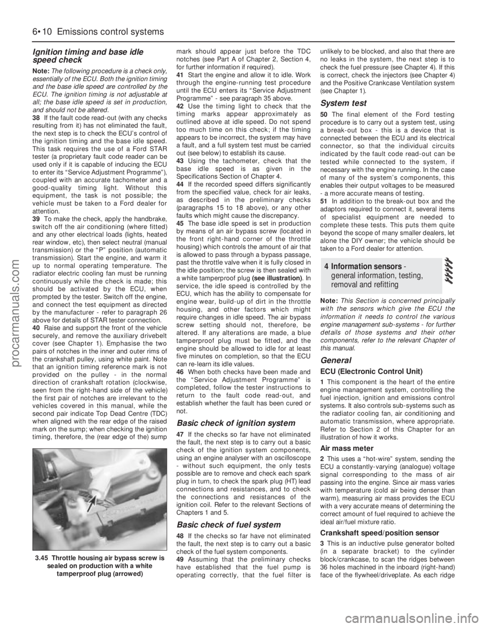
45The base idle speed is set in production
by means of an air bypass screw (located in
the front right-hand corner of the throttle
housing) which controls the amount of air that
is allowed to pass through a bypass passage,
past the throttle valve when it is fully closed in
the idle position; the screw is then sealed with
a white tamperproof plug (see illustration). In
service, the idle speed is controlled by the
ECU, which has the ability to compensate for
engine wear, build-up of dirt in the throttle
housing, and other factors which might
require changes in idle speed. The air bypass
screw setting should not, therefore, be
altered. If any alterations are made, a blue
tamperproof plug must be fitted, and the
engine should be allowed to idle for at least
five minutes on completion, so that the ECU
can re-learn its idle values.
46When both checks have been made and
the “Service Adjustment Programme” is
completed, follow the tester instructions to
return to the fault code read-out, and
establish whether the fault has been cured or
not.
Basic check of ignition system
47If the checks so far have not eliminated
the fault, the next step is to carry out a basic
check of the ignition system components,
using an engine analyser with an oscilloscope
- without such equipment, the only tests
possible are to remove and check each spark
plug in turn, to check the spark plug (HT) lead
connections and resistances, and to check
the connections and resistances of the
ignition coil. Refer to the relevant Sections of
Chapters 1 and 5.
Basic check of fuel system
48If the checks so far have not eliminated
the fault, the next step is to carry out a basic
check of the fuel system components.
49Assuming that the preliminary checks
have established that the fuel pump is
operating correctly, that the fuel filter isunlikely to be blocked, and also that there are
no leaks in the system, the next step is to
check the fuel pressure (see Chapter 4). If this
is correct, check the injectors (see Chapter 4)
and the Positive Crankcase Ventilation system
(see Chapter 1).
System test
50The final element of the Ford testing
procedure is to carry out a system test, using
a break-out box - this is a device that is
connected between the ECU and its electrical
connector, so that the individual circuits
indicated by the fault code read-out can be
tested while connected to the system, if
necessary with the engine running. In the case
of many of the system’s components, this
enables their output voltages to be measured
- a more accurate means of testing.
51In addition to the break-out box and the
adaptors required to connect it, several items
of specialist equipment are needed to
complete these tests. This puts them quite
beyond the scope of many smaller dealers, let
alone the DIY owner; the vehicle should be
taken to a Ford dealer for attention.
Note:This Section is concerned principally
with the sensors which give the ECU the
information it needs to control the various
engine management sub-systems - for further
details of those systems and their other
components, refer to the relevant Chapter of
this manual.
General
ECU (Electronic Control Unit)
1This component is the heart of the entire
engine management system, controlling the
fuel injection, ignition and emissions control
systems. It also controls sub-systems such as
the radiator cooling fan, air conditioning and
automatic transmission, where appropriate.
Refer to Section 2 of this Chapter for an
illustration of how it works.
Air mass meter
2This uses a “hot-wire” system, sending the
ECU a constantly-varying (analogue) voltage
signal corresponding to the mass of air
passing into the engine. Since air mass varies
with temperature (cold air being denser than
warm), measuring air mass provides the ECU
with a very accurate means of determining the
correct amount of fuel required to achieve the
ideal air/fuel mixture ratio.
Crankshaft speed/position sensor
3This is an inductive pulse generator bolted
(in a separate bracket) to the cylinder
block/crankcase, to scan the ridges between
36 holes machined in the inboard (right-hand)
face of the flywheel/driveplate. As each ridge
4 Information sensors -
general information, testing,
removal and refitting
6•10 Emissions control systems
3.45 Throttle housing air bypass screw is
sealed on production with a white
tamperproof plug (arrowed)
procarmanuals.com
Page 148 of 279
(where fitted) and renew it if it is damaged or
worn. Apply a smear of anti-seize compound
to the sensor’s threads, to prevent them from
welding themselves to the downpipe in
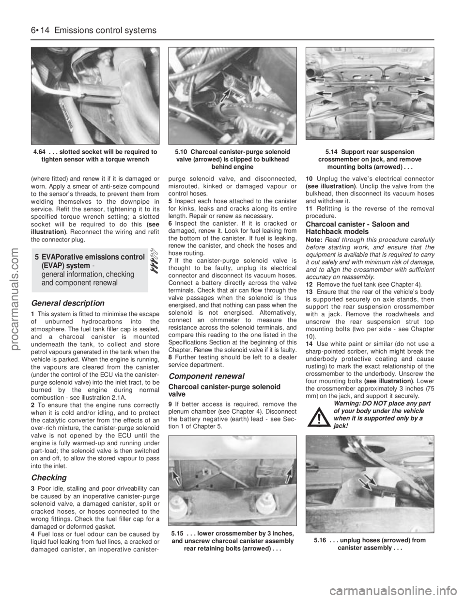
service. Refit the sensor, tightening it to its
specified torque wrench setting; a slotted
socket will be required to do this (see
illustration). Reconnect the wiring and refit
the connector plug.
General description
1This system is fitted to minimise the escape
of unburned hydrocarbons into the
atmosphere. The fuel tank filler cap is sealed,
and a charcoal canister is mounted
underneath the tank, to collect and store
petrol vapours generated in the tank when the
vehicle is parked. When the engine is running,
the vapours are cleared from the canister
(under the control of the ECU via the canister-
purge solenoid valve) into the inlet tract, to be
burned by the engine during normal
combustion - see illustration 2.1A.
2To ensure that the engine runs correctly
when it is cold and/or idling, and to protect
the catalytic converter from the effects of an
over-rich mixture, the canister-purge solenoid
valve is not opened by the ECU until the
engine is fully warmed-up and running under
part-load; the solenoid valve is then switched
on and off, to allow the stored vapour to pass
into the inlet.
Checking
3Poor idle, stalling and poor driveability can
be caused by an inoperative canister-purge
solenoid valve, a damaged canister, split or
cracked hoses, or hoses connected to the
wrong fittings. Check the fuel filler cap for a
damaged or deformed gasket.
4Fuel loss or fuel odour can be caused by
liquid fuel leaking from fuel lines, a cracked or
damaged canister, an inoperative canister-purge solenoid valve, and disconnected,
misrouted, kinked or damaged vapour or
control hoses.
5Inspect each hose attached to the canister
for kinks, leaks and cracks along its entire
length. Repair or renew as necessary.
6Inspect the canister. If it is cracked or
damaged, renew it. Look for fuel leaking from
the bottom of the canister. If fuel is leaking,
renew the canister, and check the hoses and
hose routing.
7If the canister-purge solenoid valve is
thought to be faulty, unplug its electrical
connector and disconnect its vacuum hoses.
Connect a battery directly across the valve
terminals. Check that air can flow through the
valve passages when the solenoid is thus
energised, and that nothing can pass when the
solenoid is not energised. Alternatively,
connect an ohmmeter to measure the
resistance across the solenoid terminals, and
compare this reading to the one listed in the
Specifications Section at the beginning of this
Chapter. Renew the solenoid valve if it is faulty.
8Further testing should be left to a dealer
service department.
Component renewal
Charcoal canister-purge solenoid
valve
9If better access is required, remove the
plenum chamber (see Chapter 4). Disconnect
the battery negative (earth) lead - see Sec-
tion 1 of Chapter 5.10Unplug the valve’s electrical connector
(see illustration). Unclip the valve from the
bulkhead, then disconnect its vacuum hoses
and withdraw it.
11Refitting is the reverse of the removal
procedure.
Charcoal canister - Saloon and
Hatchback models
Note:Read through this procedure carefully
before starting work, and ensure that the
equipment is available that is required to carry
it out safely and with minimum risk of damage,
and to align the crossmember with sufficient
accuracy on reassembly.
12Remove the fuel tank (see Chapter 4).
13Ensure that the rear of the vehicle’s body
is supported securely on axle stands, then
support the rear suspension crossmember
with a jack. Remove the roadwheels and
unscrew the rear suspension strut top
mounting bolts (two per side - see Chapter
10).
14Use white paint or similar (do not use a
sharp-pointed scriber, which might break the
underbody protective coating and cause
rusting) to mark the exact relationship of the
crossmember to the underbody. Unscrew the
four mounting bolts (see illustration). Lower
the crossmember approximately 3 inches (75
mm) on the jack, and support it securely.
Warning: DO NOT place any part
of your body under the vehicle
when it is supported only by a
jack!
5 EVAPorative emissions control
(EVAP) system -
general information, checking
and component renewal
6•14 Emissions control systems
4.64 . . . slotted socket will be required to
tighten sensor with a torque wrench5.10 Charcoal canister-purge solenoid
valve (arrowed) is clipped to bulkhead
behind engine5.14 Support rear suspension
crossmember on jack, and remove
mounting bolts (arrowed) . . .
5.15 . . . lower crossmember by 3 inches,
and unscrew charcoal canister assembly
rear retaining bolts (arrowed) . . .5.16 . . . unplug hoses (arrowed) from
canister assembly . . .
procarmanuals.com
Page 216 of 279
6Similarly remove the fuel gauge and
temperature gauge by unscrewing the single
screws.
7Remove all the pin contacts.
8Using a small punch, push in the multi-plug
securing pins, and remove the multi-plugs.
9Carefully lift the printed circuit from the
location dowels on the housing, taking care
not to damage it.
Refitting
10Refitting is a reversal of the removal
procedure.
Removal
1Remove the windscreen wiper arms as
described in Section 15.
2With the bonnet closed, release the grille
panel upper edge from just in front of the
windscreen, by prising off the caps and
unscrewing the upper retaining screws.
3Open the bonnet, and support with the
stay.
4Pull off the sealing strip from the cross
panel at the rear of the engine compartment.
5Unscrew the lower screws, and remove the
grille panel halves from in front of thewindscreen, withdrawing first one side and
then the other.
6Disconnect the battery negative (earth) lead
(refer to Chapter 5, Section 1).
7Reach in behind the bulkhead. Squeeze the
collar on the upper end of the speedometer
cable, where it is attached to the intermediate
cable from the rear of the speedometer head.
Disconnect the cable, and withdraw it from
the bulkhead inner panel, together with the
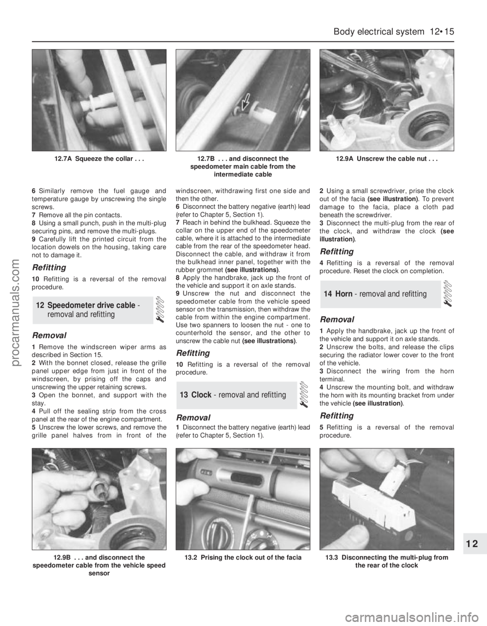
rubber grommet (see illustrations).
8Apply the handbrake, jack up the front of
the vehicle and support it on axle stands.
9Unscrew the nut and disconnect the
speedometer cable from the vehicle speed
sensor on the transmission, then withdraw the
cable from within the engine compartment.
Use two spanners to loosen the nut - one to
counterhold the sensor, and the other to
unscrew the cable nut (see illustrations).Refitting
10Refitting is a reversal of the removal
procedure.
Removal
1Disconnect the battery negative (earth) lead
(refer to Chapter 5, Section 1).2Using a small screwdriver, prise the clock
out of the facia (see illustration). To prevent
damage to the facia, place a cloth pad
beneath the screwdriver.
3Disconnect the multi-plug from the rear of
the clock, and withdraw the clock (see
illustration).
Refitting
4Refitting is a reversal of the removal
procedure. Reset the clock on completion.
Removal
1Apply the handbrake, jack up the front of
the vehicle and support it on axle stands.
2Unscrew the bolts, and release the clips
securing the radiator lower cover to the front
of the vehicle.
3Disconnect the wiring from the horn
terminal.
4Unscrew the mounting bolt, and withdraw
the horn with its mounting bracket from under
the vehicle (see illustration).
Refitting
5Refitting is a reversal of the removal
procedure.
14 Horn - removal and refitting
13 Clock- removal and refitting
12 Speedometer drive cable -
removal and refitting
Body electrical system 12•15
12
12.9B . . . and disconnect the
speedometer cable from the vehicle speed
sensor13.2 Prising the clock out of the facia13.3 Disconnecting the multi-plug from
the rear of the clock
12.7A Squeeze the collar . . .12.7B . . . and disconnect the
speedometer main cable from the
intermediate cable12.9A Unscrew the cable nut . . .
procarmanuals.com
Page 267 of 279
Engine misfires throughout the driving speed range
m mFuel filter choked (Chapter 1).
m mFuel pump faulty or delivery pressure low (Chapter 4).
m mFuel tank vent blocked or fuel pipes restricted (Chapter 4).
m mVacuum leak at the inlet manifold or associated hoses (Chap-
ters 1, 4 and 6).
m mWorn, faulty or incorrectly-gapped spark plugs (Chapter 1).
m mFaulty spark plug HT leads (Chapter 1).
m mFaulty ignition coil (Chapter 5).
m mEngine management system fault (Chapters 1, 4, 5 and 6)
m mUneven or low cylinder compressions (Chapter 2, Part A).
Engine hesitates on acceleration
m
mWorn, faulty or incorrectly-gapped spark plugs (Chapter 1).
m mEngine management system fault (Chapters 1, 4, 5 and 6).
m mVacuum leak at the inlet manifold or associated hoses (Chap-
ters 1, 4 and 6).
Engine stalls
m mIdle speed control valve faulty (Chapter 4).
m mEngine management system fault (Chapters 1, 4, 5 and 6).
m mVacuum leak at the inlet manifold or associated hoses (Chap-
ters 1, 4 and 6).
m mFuel filter choked (Chapter 1).
m mFuel pump faulty or delivery pressure low (Chapter 4).
m mFuel tank vent blocked or fuel pipes restricted (Chapter 4).
Engine lacks power
m
mIncorrect ignition timing (Chapters 5 and 6).
m mEngine management system fault (Chapters 1, 4, 5 and 6).
m mTiming belt incorrectly fitted or incorrectly tensioned (Chapter 2,
Part A).
m mFuel filter choked (Chapter 1).
m mFuel pump faulty or delivery pressure low (Chapter 4).
m mUneven or low cylinder compressions (Chapter 2, Part A).
m mWorn, faulty or incorrectly-gapped spark plugs (Chapter 1).
m mVacuum leak at the inlet manifold or associated hoses (Chap-
ters 1, 4 and 6).
m mBrakes binding (Chapters 1 and 9).
m mClutch slipping (Chapter 8).
m mAutomatic transmission fluid level incorrect (Chapter 1).
Engine runs-on after switching off
m
mIdle speed excessively high (Chapters 4 and 6).
m mEngine management system fault (Chapters 1, 4, 5 and 6).
m mExcessive carbon build-up in engine (Chapter 2, Part A).
m mHigh engine operating temperature (Chapter 3).
Engine backfires
m
mIgnition timing incorrect (Chapters 5 and 6).
m mEngine management system fault (Chapters 1, 4, 5 and 6).
m mTiming belt incorrectly fitted or incorrectly tensioned (Chapter 2,
Part A).
m mVacuum leak at the inlet manifold or associated hoses (Chap-
ters 1, 4 and 6).
Oil pressure warning light illuminated with engine
running
m mLow oil level or incorrect oil grade (Chapter 1).
m mFaulty oil pressure warning light switch (Chapter 2, Part A).
m mWorn engine bearings and/or oil pump (Chapter 2).
m mHigh engine operating temperature (Chapter 3).
m mOil pressure relief valve defective (Chapter 2, Part A).
m mOil pick-up strainer clogged (Chapter 2, Part A).
Engine noises
Pre-ignition (pinking) or knocking during acceleration or under
load
m mIgnition timing incorrect (Chapters 5 and 6).
m mIncorrect grade of fuel (Chapter 4).
m mVacuum leak at the inlet manifold or associated hoses (Chap-
ters 1, 4 and 6).
m mExcessive carbon build-up in engine (Chapter 2, Part A).
Whistling or wheezing noises
m mLeaking inlet manifold gasket (Chapter 2, Part A).
m mLeaking exhaust manifold gasket or downpipe-to-manifold joint
(Chapters 1, 2 Part A, and 4).
m mLeaking vacuum hose (Chapters 1, 4, 6 and 9).
m mBlowing cylinder head gasket (Chapter 2, Part A).
Tapping or rattling noises
m mFaulty hydraulic tappet(s) (Chapter 2, Part A).
m mWorn valve gear or camshaft (Chapter 2, Part A).
m mWorn timing belt or tensioner (Chapter 2, Part A).
m mAncillary component fault (water pump, alternator, etc) (Chap-
ters 3 and 5).
Knocking or thumping noises
m mWorn big-end bearings (regular heavy knocking, perhaps less
under load) (Chapter 2, Part B).
m mWorn main bearings (rumbling and knocking, perhaps worsening
under load) (Chapter 2, Part B).
m mPiston slap (most noticeable when cold) (Chapter 2, Part B).
m mAncillary component fault (water pump, alternator, etc) (Chap-
ters 3 and 5).
REF•8Fault Finding
2 Cooling system
Overheating
m mInsufficient coolant in system (Chapter 1).
m mThermostat faulty (Chapter 3).
m mRadiator core blocked or grille restricted (Chapter 3).
m mRadiator electric cooling fan(s) or coolant temperature sensor faulty
(Chapter 3).
m mEngine management system fault (Chapters 1, 4, 5 and 6).
m mPressure cap faulty (Chapter 3).
m mAuxiliary drivebelt worn or slipping (Chapter 1).
m mIgnition timing incorrect (Chapters 5 and 6).
m mInaccurate coolant temperature gauge sender (Chapter 3).
m mAir-lock in cooling system (Chapter 1).
Overcooling
m
mThermostat faulty (Chapter 3).
m mInaccurate coolant temperature gauge sender (Chapter 3).
External coolant leakage
m
mDeteriorated or damaged hoses or hose clips (Chapter 1).
m mRadiator core or heater matrix leaking (Chapter 3).
m mPressure cap faulty (Chapter 3).
m mWater pump seal leaking (Chapter 3).
m mBoiling due to overheating (Chapter 3).
m mCore plug leaking (Chapter 2, Part B).
procarmanuals.com
Page 274 of 279
REF•15Glossary of Technical Terms
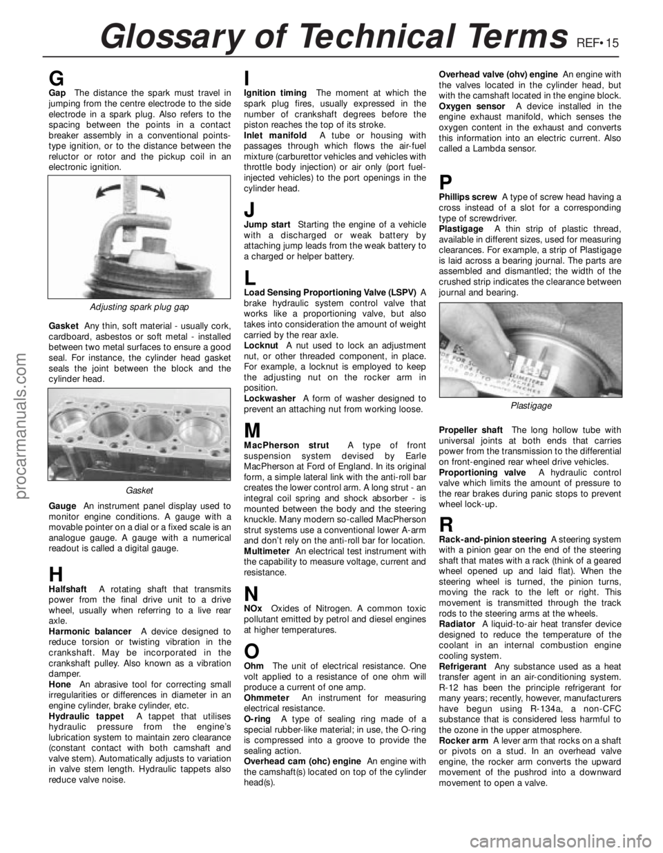
GGapThe distance the spark must travel in
jumping from the centre electrode to the side
electrode in a spark plug. Also refers to the
spacing between the points in a contact
breaker assembly in a conventional points-
type ignition, or to the distance between the
reluctor or rotor and the pickup coil in an
electronic ignition.
GasketAny thin, soft material - usually cork,
cardboard, asbestos or soft metal - installed
between two metal surfaces to ensure a good
seal. For instance, the cylinder head gasket
seals the joint between the block and the
cylinder head.
GaugeAn instrument panel display used to
monitor engine conditions. A gauge with a
movable pointer on a dial or a fixed scale is an
analogue gauge. A gauge with a numerical
readout is called a digital gauge.
HHalfshaftA rotating shaft that transmits
power from the final drive unit to a drive
wheel, usually when referring to a live rear
axle.
Harmonic balancerA device designed to
reduce torsion or twisting vibration in the
crankshaft. May be incorporated in the
crankshaft pulley. Also known as a vibration
damper.
HoneAn abrasive tool for correcting small
irregularities or differences in diameter in an
engine cylinder, brake cylinder, etc.
Hydraulic tappetA tappet that utilises
hydraulic pressure from the engine’s
lubrication system to maintain zero clearance
(constant contact with both camshaft and
valve stem). Automatically adjusts to variation
in valve stem length. Hydraulic tappets also
reduce valve noise.
IIgnition timingThe moment at which the
spark plug fires, usually expressed in the
number of crankshaft degrees before the
piston reaches the top of its stroke.
Inlet manifoldA tube or housing with
passages through which flows the air-fuel
mixture (carburettor vehicles and vehicles with
throttle body injection) or air only (port fuel-
injected vehicles) to the port openings in the
cylinder head.
JJump startStarting the engine of a vehicle
with a discharged or weak battery by
attaching jump leads from the weak battery to
a charged or helper battery.
LLoad Sensing Proportioning Valve (LSPV)A
brake hydraulic system control valve that
works like a proportioning valve, but also
takes into consideration the amount of weight
carried by the rear axle.
LocknutA nut used to lock an adjustment
nut, or other threaded component, in place.
For example, a locknut is employed to keep
the adjusting nut on the rocker arm in
position.
LockwasherA form of washer designed to
prevent an attaching nut from working loose.
MMacPherson strutA type of front
suspension system devised by Earle
MacPherson at Ford of England. In its original
form, a simple lateral link with the anti-roll bar
creates the lower control arm. A long strut - an
integral coil spring and shock absorber - is
mounted between the body and the steering
knuckle. Many modern so-called MacPherson
strut systems use a conventional lower A-arm
and don’t rely on the anti-roll bar for location.
MultimeterAn electrical test instrument with
the capability to measure voltage, current and
resistance.
NNOxOxides of Nitrogen. A common toxic
pollutant emitted by petrol and diesel engines
at higher temperatures.
OOhmThe unit of electrical resistance. One
volt applied to a resistance of one ohm will
produce a current of one amp.
OhmmeterAn instrument for measuring
electrical resistance.
O-ringA type of sealing ring made of a
special rubber-like material; in use, the O-ring
is compressed into a groove to provide the
sealing action.
Overhead cam (ohc) engineAn engine with
the camshaft(s) located on top of the cylinder
head(s).Overhead valve (ohv) engineAn engine with
the valves located in the cylinder head, but
with the camshaft located in the engine block.
Oxygen sensorA device installed in the
engine exhaust manifold, which senses the
oxygen content in the exhaust and converts
this information into an electric current. Also
called a Lambda sensor.
PPhillips screwA type of screw head having a
cross instead of a slot for a corresponding
type of screwdriver.
PlastigageA thin strip of plastic thread,
available in different sizes, used for measuring
clearances. For example, a strip of Plastigage
is laid across a bearing journal. The parts are
assembled and dismantled; the width of the
crushed strip indicates the clearance between
journal and bearing.
Propeller shaftThe long hollow tube with
universal joints at both ends that carries
power from the transmission to the differential
on front-engined rear wheel drive vehicles.
Proportioning valveA hydraulic control
valve which limits the amount of pressure to
the rear brakes during panic stops to prevent
wheel lock-up.
RRack-and-pinion steeringA steering system
with a pinion gear on the end of the steering
shaft that mates with a rack (think of a geared
wheel opened up and laid flat). When the
steering wheel is turned, the pinion turns,
moving the rack to the left or right. This
movement is transmitted through the track
rods to the steering arms at the wheels.
RadiatorA liquid-to-air heat transfer device
designed to reduce the temperature of the
coolant in an internal combustion engine
cooling system.
RefrigerantAny substance used as a heat
transfer agent in an air-conditioning system.
R-12 has been the principle refrigerant for
many years; recently, however, manufacturers
have begun using R-134a, a non-CFC
substance that is considered less harmful to
the ozone in the upper atmosphere.
Rocker armA lever arm that rocks on a shaft
or pivots on a stud. In an overhead valve
engine, the rocker arm converts the upward
movement of the pushrod into a downward
movement to open a valve.
Adjusting spark plug gap
Plastigage
Gasket
procarmanuals.com