1993 FORD MONDEO alternator belt
[x] Cancel search: alternator beltPage 75 of 279
gear linkage heat shield. Reconnect the
gearchange linkage and transmission support
rods to the transmission, adjusting the linkage
using the marks made on removal (see
Chapter 7, Part A, for details).
56Re-install the remaining components and
fasteners in the reverse order of removal.
57Add coolant, engine oil and transmission
fluids as needed (see Chapter 1).
58Run the engine, and check for proper
operation and the absence of leaks. Shut off
the engine, and recheck the fluid levels.
59Remember that, since the front suspension
subframe and steering gear have been
disturbed, the wheel alignment and steering
angles must be checked fully and carefully as
soon as possible, with any necessary
adjustments being made. This operation is best
carried out by an experienced mechanic, using
proper checking equipment; the vehicle should
therefore be taken to a Ford dealer or similarly-
qualified person for attention.
1It is much easier to dismantle and work on
the engine if it is mounted on a portable engine
stand. These stands can often be hired from a
tool hire shop. Before the engine is mounted
on a stand, the flywheel/driveplate should be
removed (Part A of this Chapter, Section 21)
so that the stand bolts can be tightened into
the end of the cylinder block/crankcase.
2If a stand is not available, it is possible to
dismantle the engine with it mounted on
blocks, on a sturdy workbench or on the floor.
Be extra-careful not to tip or drop the engine
when working without a stand.
3If you are going to obtain a reconditioned
engine, all external components must be
removed first, to be transferred to the
replacement engine (just as they will if you are
doing a complete engine overhaul yourself).
Note:When removing the external
components from the engine, pay close
attention to details that may be helpful or
important during refitting. Note the fitted
position of gaskets, seals, spacers, pins,
washers, bolts and other small items.These
external components include the following:
(a) Alternator and brackets (Chapter 5).
(b) HT leads and spark plugs (Chapter 1).
(c) Thermostat and housing (Chapter 3).
(d) Dipstick tube.
(e) Fuel injection system components
(Chapter 4).
(f) All electrical switches and sensors - refer
to the appropriate Chapter.
(g) Inlet and exhaust manifolds (Part A of this
Chapter).
(h) Oil filter (Chapter 1).
(i) Engine/transmission mounting brackets
(Part A of this Chapter, Section 22).
(j) Flywheel/driveplate (Part A of this
Chapter, Section 21).
4If you are obtaining a “short” engine (whichconsists of the engine cylinder
block/crankcase, crankshaft, pistons and
connecting rods all assembled), then the
cylinder head, sump, oil pump, and timing belt
will have to be removed also.
5If you are planning a complete overhaul, the
engine can be dismantled and the internal
components removed in the following order.
(a) Inlet and exhaust manifolds (Part A of this
Chapter).
(b) Timing belt, toothed pulleys and
tensioner, and timing belt inner cover
(Part A of this Chapter).
(c) Cylinder head (Part A of this Chapter,
Section 14).
(d) Flywheel/driveplate (Part A of this
Chapter, Section 21).
(e) Sump (Part A of this Chapter, Section 15).
(f) Oil pump (Part A of this Chapter, Sec-
tion 16).
(g) Piston/connecting rod assemblies
(Section 9).
(h) Crankshaft (Section 10).
6Before beginning the dismantling andoverhaul procedures, make sure that you have
all of the correct tools necessary. Refer to the
introductory pages at the beginning of this
manual for further information.
Note:New and reconditioned cylinder heads
are available from the manufacturers, and
from engine overhaul specialists. Due to the
fact that some specialist tools are required for
the dismantling and inspection procedures,
and new components may not be readily
available (refer to Section 1 of this Part), it may
be more practical and economical for the
home mechanic to purchase a reconditioned
head, rather than to dismantle, inspect and
recondition the original head.
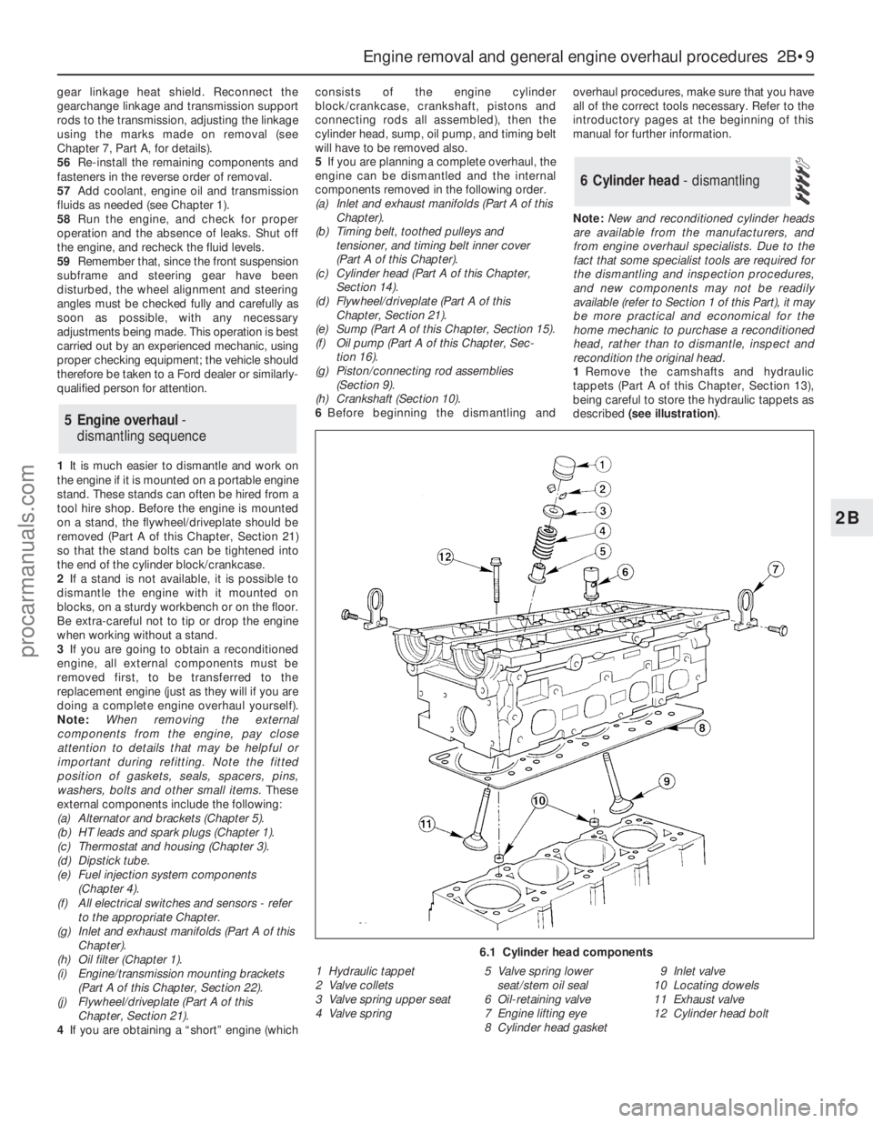
1Remove the camshafts and hydraulic
tappets (Part A of this Chapter, Section 13),
being careful to store the hydraulic tappets as
described (see illustration).
6 Cylinder head - dismantling
5 Engine overhaul-
dismantling sequence
Engine removal and general engine overhaul procedures 2B•9
2B
6.1 Cylinder head components
1 Hydraulic tappet
2 Valve collets
3 Valve spring upper seat
4 Valve spring5 Valve spring lower
seat/stem oil seal
6 Oil-retaining valve
7 Engine lifting eye
8 Cylinder head gasket9 Inlet valve
10 Locating dowels
11 Exhaust valve
12 Cylinder head bolt
procarmanuals.com
Page 111 of 279
Chapter 5 Engine electrical systems
Alternator - removal and refitting . . . . . . . . . . . . . . . . . . . . . . . . . . . 12
Alternator brushes and voltage regulator - renewal . . . . . . . . . . . . . 13
Auxiliary drivebelt check and renewal . . . . . . . . . . . . . See Chapter 1
Battery - removal and refitting . . . . . . . . . . . . . . . . . . . . . . . . . . . . . 2
Battery check, maintenance and charging . . . . . . . . . See Chapter 1
Battery leads - check and renewal . . . . . . . . . . . . . . . . . . . . . . . . . . 3
Charging system - general information and precautions . . . . . . . . . 10
Charging system - testing . . . . . . . . . . . . . . . . . . . . . . . . . . . . . . . . . 11
Crankshaft speed/position sensor - checking, removal and refitting 9
Electronic control system - information and
fault diagnosis . . . . . . . . . . . . . . . . . . . . . . . . . . . . . See Chapter 6
Electronic Control Unit (ECU) and system information
sensors - general information . . . . . . . . . . . . . . . . . See Chapter 6Engine compartment wiring check . . . . . . . . . . . . . . . See Chapter 1
General information, precautions and battery disconnection . . . . . . 1
Ignition coil - removal and refitting . . . . . . . . . . . . . . . . . . . . . . . . . . 6
Ignition module (automatic transmission models only) -
removal and refitting . . . . . . . . . . . . . . . . . . . . . . . . . . . . . . . . . . . 7
Ignition system - general information and precautions . . . . . . . . . . . 4
Ignition system - testing . . . . . . . . . . . . . . . . . . . . . . . . . . . . . . . . . . 5
Ignition timing - checking . . . . . . . . . . . . . . . . . . . . . . . . . . . . . . . . . 8
Spark plug renewal and HT lead check . . . . . . . . . . . . See Chapter 1
Starter motor - brush and solenoid renewal . . . . . . . . . . . . . . . . . . . 17
Starter motor - removal and refitting . . . . . . . . . . . . . . . . . . . . . . . . . 16
Starting system - general information and precautions . . . . . . . . . . 14
Starting system - testing . . . . . . . . . . . . . . . . . . . . . . . . . . . . . . . . . . 15
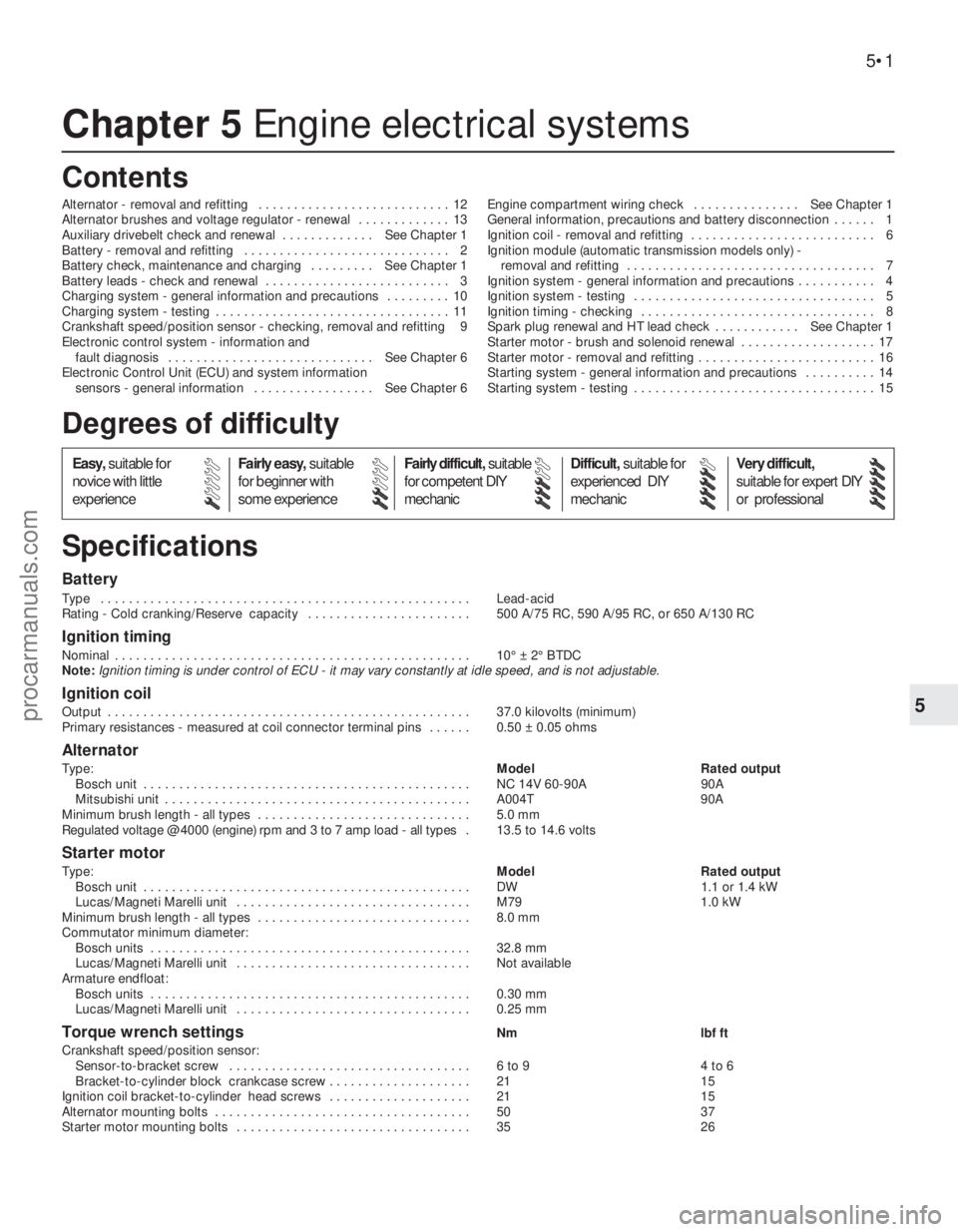
Battery
Type . . . . . . . . . . . . . . . . . . . . . . . . . . . . . . . . . . . . . . . . . . . . . . . . . . . . Lead-acid
Rating - Cold cranking/Reserve capacity . . . . . . . . . . . . . . . . . . . . . . . 500 A/75 RC, 590 A/95 RC, or 650 A/130 RC
Ignition timing
Nominal . . . . . . . . . . . . . . . . . . . . . . . . . . . . . . . . . . . . . . . . . . . . . . . . . . 10° ± 2° BTDC
Note:Ignition timing is under control of ECU - it may vary constantly at idle speed, and is not adjustable.
Ignition coil
Output . . . . . . . . . . . . . . . . . . . . . . . . . . . . . . . . . . . . . . . . . . . . . . . . . . . 37.0 kilovolts (minimum)
Primary resistances - measured at coil connector terminal pins . . . . . . 0.50 ± 0.05 ohms
Alternator
Type:Model Rated output
Bosch unit . . . . . . . . . . . . . . . . . . . . . . . . . . . . . . . . . . . . . . . . . . . . . . NC 14V 60-90A 90A
Mitsubishi unit . . . . . . . . . . . . . . . . . . . . . . . . . . . . . . . . . . . . . . . . . . . A004T 90A
Minimum brush length - all types . . . . . . . . . . . . . . . . . . . . . . . . . . . . . . 5.0 mm
Regulated voltage @ 4000 (engine) rpm and 3 to 7 amp load - all types .13.5 to 14.6 volts
Starter motor
Type:Model Rated output
Bosch unit . . . . . . . . . . . . . . . . . . . . . . . . . . . . . . . . . . . . . . . . . . . . . . DW 1.1 or 1.4 kW
Lucas/Magneti Marelli unit . . . . . . . . . . . . . . . . . . . . . . . . . . . . . . . . . M79 1.0 kW
Minimum brush length - all types . . . . . . . . . . . . . . . . . . . . . . . . . . . . . . 8.0 mm
Commutator minimum diameter:
Bosch units . . . . . . . . . . . . . . . . . . . . . . . . . . . . . . . . . . . . . . . . . . . . . 32.8 mm
Lucas/Magneti Marelli unit . . . . . . . . . . . . . . . . . . . . . . . . . . . . . . . . . Not available
Armature endfloat:
Bosch units . . . . . . . . . . . . . . . . . . . . . . . . . . . . . . . . . . . . . . . . . . . . . 0.30 mm
Lucas/Magneti Marelli unit . . . . . . . . . . . . . . . . . . . . . . . . . . . . . . . . . 0.25 mm
Torque wrench settingsNm lbf ft
Crankshaft speed/position sensor:
Sensor-to-bracket screw . . . . . . . . . . . . . . . . . . . . . . . . . . . . . . . . . . 6 to 9 4 to 6
Bracket-to-cylinder block crankcase screw . . . . . . . . . . . . . . . . . . . . 21 15
Ignition coil bracket-to-cylinder head screws . . . . . . . . . . . . . . . . . . . . 21 15
Alternator mounting bolts . . . . . . . . . . . . . . . . . . . . . . . . . . . . . . . . . . . . 50 37
Starter motor mounting bolts . . . . . . . . . . . . . . . . . . . . . . . . . . . . . . . . . 35 26
5•1
Easy,suitable for
novice with little
experienceFairly easy,suitable
for beginner with
some experienceFairly difficult,suitable
for competent DIY
mechanicDifficult,suitable for
experienced DIY
mechanicVery difficult,
suitable for expert DIY
or professional
Degrees of difficulty
Specifications Contents
5
procarmanuals.com
Page 115 of 279
5Undo the sensor’s retaining screw and
withdraw the sensor. The sensor’s bracket
cannot be unbolted from the cylinder
block/crankcase unless the transmission and
flywheel/driveplate have been removed (see
Chapter 2).
6Refitting is the reverse of the removal
procedure.
General information
The charging system includes the
alternator, an internal voltage regulator, a no-
charge (or “ignition”) warning light, the
battery, and the wiring between all the
components. The charging system supplies
electrical power for the ignition system, the
lights, the radio, etc. The alternator is driven
by the auxiliary drivebelt at the front (right-
hand end) of the engine.
The purpose of the voltage regulator is to
limit the alternator’s voltage to a preset value.
This prevents power surges, circuit overloads,
etc., during peak voltage output.
The charging system doesn’t ordinarily
require periodic maintenance. However, the
drivebelt, battery and wires and connections
should be inspected at the intervals outlined
in Chapter 1.
The dashboard warning light should come
on when the ignition key is turned to positions
“II” or “III”, then should go off immediately the
engine starts. If it remains on, or if it comes on
while the engine is running, there is a
malfunction in the charging system (see
Section 11). If the light does not come on
when the ignition key is turned, and the bulb is
sound (see Chapter 12), there is a fault in the
alternator.
Precautions
Be very careful when making electrical
circuit connections to a vehicle equipped with
an alternator, and note the following:
(a) When reconnecting wires to the alternator
from the battery, be sure to note the
polarity.
(b) Before using arc-welding equipment to
repair any part of the vehicle, disconnect
the wires from the alternator and the
battery terminals.
(c) Never start the engine with a battery
charger connected.
(d) Always disconnect both battery leads
before using a battery charger.
(e) The alternator is driven by an engine
drivebelt which could cause serious injury
if your hand, hair or clothes become
entangled in it with the engine running.
(f) Because the alternator is connected
directly to the battery, it could arc or
cause a fire if overloaded or shorted-out.
(g) Wrap a plastic bag over the alternator,
and secure it with rubber bands, beforesteam-cleaning or pressure-washing the
engine.
(h) Never disconnect the alternator terminals
while the engine is running.
1If a malfunction occurs in the charging
circuit, don’t automatically assume that the
alternator is causing the problem. First check
the following items:
(a) Check the tension and condition of the
auxiliary drivebelt - renew it if it is worn or
deteriorated (see Chapter 1).
(b) Ensure the alternator mounting bolts and
nuts are tight.
(c) Inspect the alternator wiring harness and
the electrical connections at the
alternator; they must be in good
condition, and tight.
(d) Check the large main fuses in the engine
compartment (see Chapter 12). If any is
blown, determine the cause, repair the
circuit and renew the fuse (the vehicle
won’t start and/or the accessories won’t
work if the fuse is blown).
(e) Start the engine and check the alternator
for abnormal noises - for example, a
shrieking or squealing sound may indicate
a badly-worn bearing or brush.
(f) Make sure that the battery is fully-charged
- one bad cell in a battery can cause
overcharging by the alternator.
(g) Disconnect the battery leads (negative
first, then positive). Inspect the battery
posts and the lead clamps for corrosion.
Clean them thoroughly if necessary (see
Section 3 and Chapter 1). Reconnect the
lead to the negative terminal.
(h) With the ignition and all accessories
switched off, insert a test light between
the battery negative post and the
disconnected negative lead clamp:
(1) If the test light does not come on, re-
attach the clamp and proceed to the next
step.
(2) If the test light comes on, there is a short
in the electrical system of the vehicle. The
short must be repaired before the
charging system can be checked.
(3) To find the short, disconnect the
alternator wiring harness:
(a) If the light goes out, the alternator is
at fault.
(b) If the light stays on, remove each fuse
until it goes out - this will tell you
which component is short-circuited.
2Using a voltmeter, check the battery
voltage with the engine off. It should be
approximately 12 volts.
3Start the engine and check the battery
voltage again. Increase engine speed until the
voltmeter reading remains steady; it should
now be approximately 13.5 to 14.6 volts.
4Switch on as many electrical accessories
(eg the headlights, heated rear window andheater blower) as possible, and check that the
alternator maintains the regulated voltage at
around 13 to 14 volts. The voltage may drop
and then come back up; it may also be
necessary to increase engine speed slightly,
even if the charging system is working
properly.
5If the voltage reading is greater than the
specified charging voltage, renew the voltage
regulator (see Section 13).
6If the voltmeter reading is less than that
specified, the fault may be due to worn
brushes, weak brush springs, a faulty voltage
regulator, a faulty diode, a severed phase
winding, or worn or damaged slip rings. The
brushes and slip rings may be checked (see
Section 13), but if the fault persists, the
alternator should be renewed or taken to an
auto-electrician for testing and repair.
1Disconnect the battery negative (earth) lead
- see Section 1.
2Remove the plenum chamber (see Chap-
ter 4).
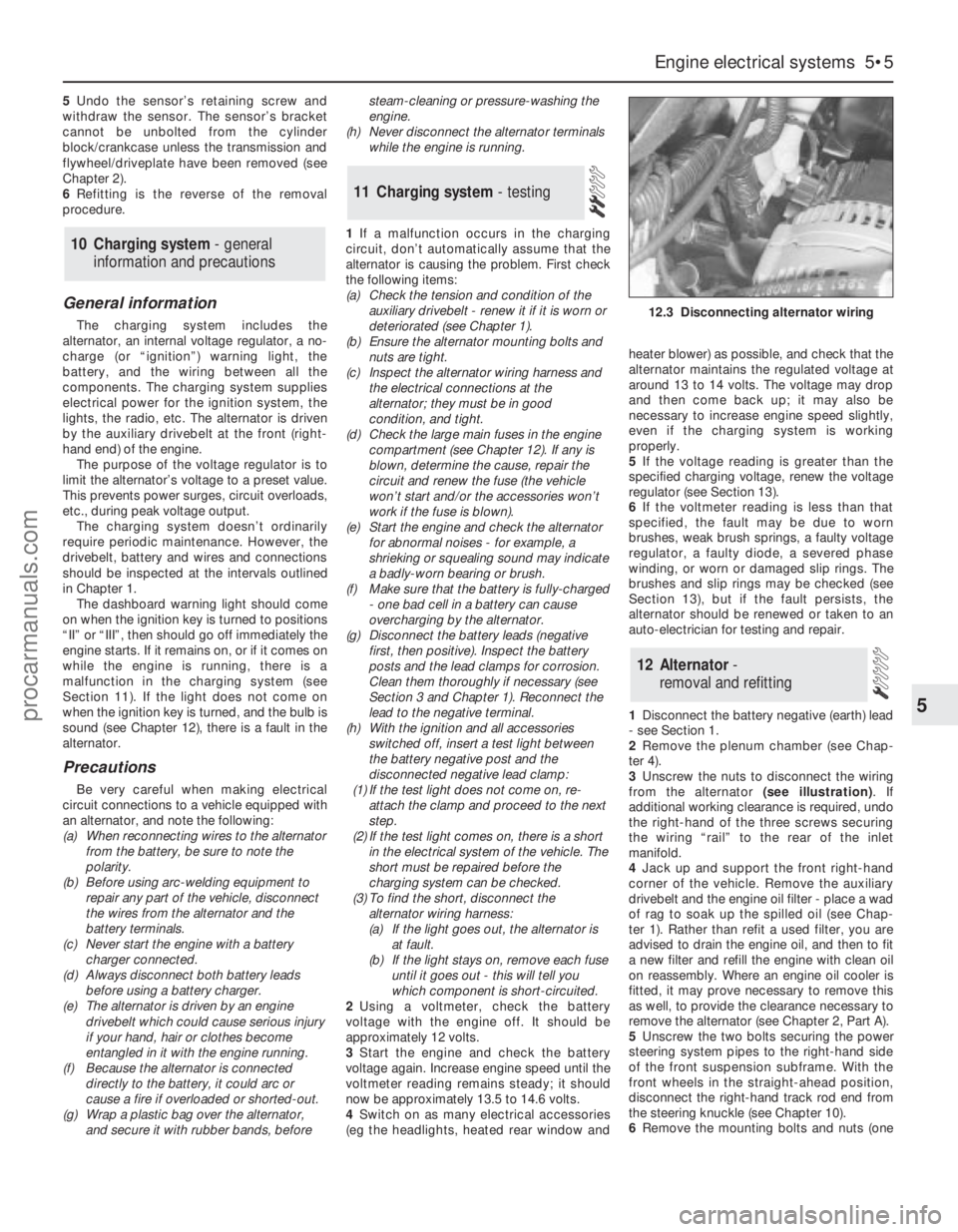
3Unscrew the nuts to disconnect the wiring
from the alternator (see illustration). If
additional working clearance is required, undo
the right-hand of the three screws securing
the wiring “rail” to the rear of the inlet
manifold.
4Jack up and support the front right-hand
corner of the vehicle. Remove the auxiliary
drivebelt and the engine oil filter - place a wad
of rag to soak up the spilled oil (see Chap-
ter 1). Rather than refit a used filter, you are
advised to drain the engine oil, and then to fit
a new filter and refill the engine with clean oil
on reassembly. Where an engine oil cooler is
fitted, it may prove necessary to remove this
as well, to provide the clearance necessary to
remove the alternator (see Chapter 2, Part A).
5Unscrew the two bolts securing the power
steering system pipes to the right-hand side
of the front suspension subframe. With the
front wheels in the straight-ahead position,
disconnect the right-hand track rod end from
the steering knuckle (see Chapter 10).
6Remove the mounting bolts and nuts (one
12 Alternator-
removal and refitting
11 Charging system- testing
10 Charging system - general
information and precautions
Engine electrical systems 5•5
5
12.3 Disconnecting alternator wiring
procarmanuals.com
Page 267 of 279
Engine misfires throughout the driving speed range
m mFuel filter choked (Chapter 1).
m mFuel pump faulty or delivery pressure low (Chapter 4).
m mFuel tank vent blocked or fuel pipes restricted (Chapter 4).
m mVacuum leak at the inlet manifold or associated hoses (Chap-
ters 1, 4 and 6).
m mWorn, faulty or incorrectly-gapped spark plugs (Chapter 1).
m mFaulty spark plug HT leads (Chapter 1).
m mFaulty ignition coil (Chapter 5).
m mEngine management system fault (Chapters 1, 4, 5 and 6)
m mUneven or low cylinder compressions (Chapter 2, Part A).
Engine hesitates on acceleration
m
mWorn, faulty or incorrectly-gapped spark plugs (Chapter 1).
m mEngine management system fault (Chapters 1, 4, 5 and 6).
m mVacuum leak at the inlet manifold or associated hoses (Chap-
ters 1, 4 and 6).
Engine stalls
m mIdle speed control valve faulty (Chapter 4).
m mEngine management system fault (Chapters 1, 4, 5 and 6).
m mVacuum leak at the inlet manifold or associated hoses (Chap-
ters 1, 4 and 6).
m mFuel filter choked (Chapter 1).
m mFuel pump faulty or delivery pressure low (Chapter 4).
m mFuel tank vent blocked or fuel pipes restricted (Chapter 4).
Engine lacks power
m
mIncorrect ignition timing (Chapters 5 and 6).
m mEngine management system fault (Chapters 1, 4, 5 and 6).
m mTiming belt incorrectly fitted or incorrectly tensioned (Chapter 2,
Part A).
m mFuel filter choked (Chapter 1).
m mFuel pump faulty or delivery pressure low (Chapter 4).
m mUneven or low cylinder compressions (Chapter 2, Part A).
m mWorn, faulty or incorrectly-gapped spark plugs (Chapter 1).
m mVacuum leak at the inlet manifold or associated hoses (Chap-
ters 1, 4 and 6).
m mBrakes binding (Chapters 1 and 9).
m mClutch slipping (Chapter 8).
m mAutomatic transmission fluid level incorrect (Chapter 1).
Engine runs-on after switching off
m
mIdle speed excessively high (Chapters 4 and 6).
m mEngine management system fault (Chapters 1, 4, 5 and 6).
m mExcessive carbon build-up in engine (Chapter 2, Part A).
m mHigh engine operating temperature (Chapter 3).
Engine backfires
m
mIgnition timing incorrect (Chapters 5 and 6).
m mEngine management system fault (Chapters 1, 4, 5 and 6).
m mTiming belt incorrectly fitted or incorrectly tensioned (Chapter 2,
Part A).
m mVacuum leak at the inlet manifold or associated hoses (Chap-
ters 1, 4 and 6).
Oil pressure warning light illuminated with engine
running
m mLow oil level or incorrect oil grade (Chapter 1).
m mFaulty oil pressure warning light switch (Chapter 2, Part A).
m mWorn engine bearings and/or oil pump (Chapter 2).
m mHigh engine operating temperature (Chapter 3).
m mOil pressure relief valve defective (Chapter 2, Part A).
m mOil pick-up strainer clogged (Chapter 2, Part A).
Engine noises
Pre-ignition (pinking) or knocking during acceleration or under
load
m mIgnition timing incorrect (Chapters 5 and 6).
m mIncorrect grade of fuel (Chapter 4).
m mVacuum leak at the inlet manifold or associated hoses (Chap-
ters 1, 4 and 6).
m mExcessive carbon build-up in engine (Chapter 2, Part A).
Whistling or wheezing noises
m mLeaking inlet manifold gasket (Chapter 2, Part A).
m mLeaking exhaust manifold gasket or downpipe-to-manifold joint
(Chapters 1, 2 Part A, and 4).
m mLeaking vacuum hose (Chapters 1, 4, 6 and 9).
m mBlowing cylinder head gasket (Chapter 2, Part A).
Tapping or rattling noises
m mFaulty hydraulic tappet(s) (Chapter 2, Part A).
m mWorn valve gear or camshaft (Chapter 2, Part A).
m mWorn timing belt or tensioner (Chapter 2, Part A).
m mAncillary component fault (water pump, alternator, etc) (Chap-
ters 3 and 5).
Knocking or thumping noises
m mWorn big-end bearings (regular heavy knocking, perhaps less
under load) (Chapter 2, Part B).
m mWorn main bearings (rumbling and knocking, perhaps worsening
under load) (Chapter 2, Part B).
m mPiston slap (most noticeable when cold) (Chapter 2, Part B).
m mAncillary component fault (water pump, alternator, etc) (Chap-
ters 3 and 5).
REF•8Fault Finding
2 Cooling system
Overheating
m mInsufficient coolant in system (Chapter 1).
m mThermostat faulty (Chapter 3).
m mRadiator core blocked or grille restricted (Chapter 3).
m mRadiator electric cooling fan(s) or coolant temperature sensor faulty
(Chapter 3).
m mEngine management system fault (Chapters 1, 4, 5 and 6).
m mPressure cap faulty (Chapter 3).
m mAuxiliary drivebelt worn or slipping (Chapter 1).
m mIgnition timing incorrect (Chapters 5 and 6).
m mInaccurate coolant temperature gauge sender (Chapter 3).
m mAir-lock in cooling system (Chapter 1).
Overcooling
m
mThermostat faulty (Chapter 3).
m mInaccurate coolant temperature gauge sender (Chapter 3).
External coolant leakage
m
mDeteriorated or damaged hoses or hose clips (Chapter 1).
m mRadiator core or heater matrix leaking (Chapter 3).
m mPressure cap faulty (Chapter 3).
m mWater pump seal leaking (Chapter 3).
m mBoiling due to overheating (Chapter 3).
m mCore plug leaking (Chapter 2, Part B).
procarmanuals.com
Page 271 of 279
REF•12
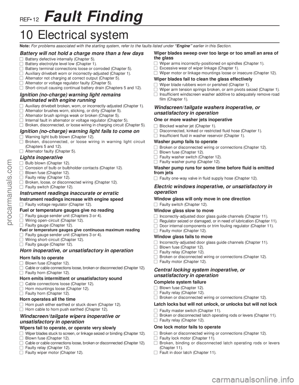
Battery will not hold a charge more than a few days
m mBattery defective internally (Chapter 5).
m mBattery electrolyte level low (Chapter 1).
m mBattery terminal connections loose or corroded (Chapter 5).
m mAuxiliary drivebelt worn or incorrectly-adjusted (Chapter 1).
m mAlternator not charging at correct output (Chapter 5).
m mAlternator or voltage regulator faulty (Chapter 5).
m mShort-circuit causing continual battery drain (Chapters 5 and 12).
Ignition (no-charge) warning light remains
illuminated with engine running
m mAuxiliary drivebelt broken, worn, or incorrectly-adjusted (Chapter 1).
m mAlternator brushes worn, sticking, or dirty (Chapter 5).
m mAlternator brush springs weak or broken (Chapter 5).
m mInternal fault in alternator or voltage regulator (Chapter 5).
m mBroken, disconnected, or loose wiring in charging circuit (Chapter 5).
Ignition (no-charge) warning light fails to come on
m
mWarning light bulb blown (Chapter 12).
m mBroken, disconnected, or loose wiring in warning light circuit
(Chapters 5 and 12).
m mAlternator faulty (Chapter 5).
Lights inoperative
m
mBulb blown (Chapter 12).
m mCorrosion of bulb or bulbholder contacts (Chapter 12).
m mBlown fuse (Chapter 12).
m mFaulty relay (Chapter 12).
m mBroken, loose, or disconnected wiring (Chapter 12).
m mFaulty switch (Chapter 12).
Instrument readings inaccurate or erratic
Instrument readings increase with engine speed
m
mFaulty voltage regulator (Chapter 12).
Fuel or temperature gauges give no reading
m
mFaulty gauge sender unit (Chapters 3 or 4).
m mWiring open-circuit (Chapter 12).
m mFaulty gauge (Chapter 12).
Fuel or temperature gauges give continuous maximum reading
m mFaulty gauge sender unit (Chapters 3 or 4).
m mWiring short-circuit (Chapter 12).
m mFaulty gauge (Chapter 12).
Horn inoperative, or unsatisfactory in operation
Horn fails to operate
m
mBlown fuse (Chapter 12).
m mCable or cable connections loose, broken or disconnected (Chapter 12).
m mFaulty horn (Chapter 12).
Horn emits intermittent or unsatisfactory sound
m
mCable connections loose (Chapter 12).
m mHorn mountings loose (Chapter 12).
m mFaulty horn (Chapter 12).
Horn operates all the time
m
mHorn push either earthed or stuck down (Chapter 12).
m mHorn cable to horn push earthed (Chapter 12).
Windscreen/tailgate wipers inoperative or
unsatisfactory in operation
Wipers fail to operate, or operate very slowly
m mWiper blades stuck to screen, or linkage seized or binding (Chapter 12).
m mBlown fuse (Chapter 12).
m mCable or cable connections loose, broken or disconnected (Chapter 12).
m mFaulty relay (Chapter 12).
m mFaulty wiper motor (Chapter 12).
Wiper blades sweep over too large or too small an area of
the glass
m mWiper arms incorrectly-positioned on spindles (Chapter 1).
m mExcessive wear of wiper linkage (Chapter 1).
m mWiper motor or linkage mountings loose or insecure (Chapter 12).
Wiper blades fail to clean the glass effectively
m
mWiper blade rubbers worn or perished (Chapter 1).
m mWiper arm tension springs broken, or arm pivots seized (Chapter 1).
m mInsufficient windscreen washer additive to adequately remove road
film (Chapter 1).
Windscreen/tailgate washers inoperative, or
unsatisfactory in operation
One or more washer jets inoperative
m mBlocked washer jet (Chapter 1).
m mDisconnected, kinked or restricted fluid hose (Chapter 1).
m mInsufficient fluid in washer reservoir (Chapter 1).
Washer pump fails to operate
m
mBroken or disconnected wiring or connections (Chapter 12).
m mBlown fuse (Chapter 12).
m mFaulty washer switch (Chapter 12).
m mFaulty washer pump (Chapter 12).
Washer pump runs for some time before fluid is emitted
from jets
m mFaulty one-way valve in fluid supply hose (Chapter 12).
Electric windows inoperative, or unsatisfactory in
operation
Window glass will only move in one direction
m mFaulty switch (Chapter 12).
Window glass slow to move
m
mIncorrectly-adjusted door glass guide channels (Chapter 11).
m mRegulator seized or damaged, or in need of lubrication (Chapter 11).
m mDoor internal components or trim fouling regulator (Chapter 11).
m mFaulty motor (Chapter 12).
Window glass fails to move
m
mIncorrectly-adjusted door glass guide channels (Chapter 11).
m mBlown fuse (Chapter 12).
m mFaulty relay (Chapter 12).
m mBroken or disconnected wiring or connections (Chapter 12).
m mFaulty motor (Chapter 12).
Central locking system inoperative, or
unsatisfactory in operation
Complete system failure
m mBlown fuse (Chapter 12).
m mFaulty relay (Chapter 12).
m mBroken or disconnected wiring or connections (Chapter 12).
Latch locks but will not unlock, or unlocks but will not lock
m
mFaulty master switch (Chapter 11).
m mBroken or disconnected latch operating rods or levers (Chapter 11).
m mFaulty relay (Chapter 12).
One lock motor fails to operate
m
mBroken or disconnected wiring or connections (Chapter 12).
m mFaulty lock motor (Chapter 11).
m mBroken, binding or disconnected latch operating rods or levers
(Chapter 11).
m mFault in door latch (Chapter 11).
Fault Finding
10 Electrical system
Note:For problems associated with the starting system, refer to the faults listed under “Engine”earlier in this Section.
procarmanuals.com
Page 272 of 279
REF•13Glossary of Technical Terms
A
ABS (Anti-lock brake system)A system,
usually electronically controlled, that senses
incipient wheel lockup during braking and
relieves hydraulic pressure at wheels that are
about to skid.
Air bag An inflatable bag hidden in the
steering wheel (driver’s side) or the dash or
glovebox (passenger side). In a head-on
collision, the bags inflate, preventing the
driver and front passenger from being thrown
forward into the steering wheel or windscreen.
Air cleanerA metal or plastic housing,
containing a filter element, which removes
dust and dirt from the air being drawn into the
engine.
Air filter elementThe actual filter in an air
cleaner system, usually manufactured from
pleated paper and requiring renewal at regular
intervals.
Allen keyA hexagonal wrench which fits into
a recessed hexagonal hole.
Alligator clipA long-nosed spring-loaded
metal clip with meshing teeth. Used to make
temporary electrical connections.
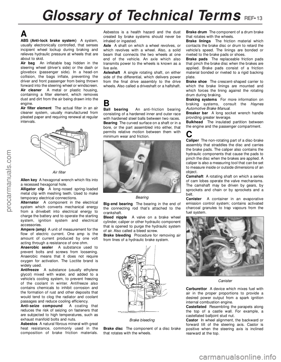
AlternatorA component in the electrical
system which converts mechanical energy
from a drivebelt into electrical energy to
charge the battery and to operate the starting
system, ignition system and electrical
accessories.
Ampere (amp)A unit of measurement for the
flow of electric current. One amp is the
amount of current produced by one volt
acting through a resistance of one ohm.
Anaerobic sealerA substance used to
prevent bolts and screws from loosening.
Anaerobic means that it does not require
oxygen for activation. The Loctite brand is
widely used.
AntifreezeA substance (usually ethylene
glycol) mixed with water, and added to a
vehicle’s cooling system, to prevent freezing
of the coolant in winter. Antifreeze also
contains chemicals to inhibit corrosion and
the formation of rust and other deposits that
would tend to clog the radiator and coolant
passages and reduce cooling efficiency.
Anti-seize compoundA coating that
reduces the risk of seizing on fasteners that
are subjected to high temperatures, such as
exhaust manifold bolts and nuts.
AsbestosA natural fibrous mineral with great
heat resistance, commonly used in the
composition of brake friction materials.Asbestos is a health hazard and the dust
created by brake systems should never be
inhaled or ingested.
AxleA shaft on which a wheel revolves, or
which revolves with a wheel. Also, a solid
beam that connects the two wheels at one
end of the vehicle. An axle which also
transmits power to the wheels is known as a
live axle.
AxleshaftA single rotating shaft, on either
side of the differential, which delivers power
from the final drive assembly to the drive
wheels. Also called a driveshaft or a halfshaft.
BBall bearingAn anti-friction bearing
consisting of a hardened inner and outer race
with hardened steel balls between two races.
BearingThe curved surface on a shaft or in a
bore, or the part assembled into either, that
permits relative motion between them with
minimum wear and friction.
Big-end bearingThe bearing in the end of
the connecting rod that’s attached to the
crankshaft.
Bleed nippleA valve on a brake wheel
cylinder, caliper or other hydraulic component
that is opened to purge the hydraulic system
of air. Also called a bleed screw.
Brake bleedingProcedure for removing air
from lines of a hydraulic brake system.
Brake discThe component of a disc brake
that rotates with the wheels.Brake drumThe component of a drum brake
that rotates with the wheels.
Brake liningsThe friction material which
contacts the brake disc or drum to retard the
vehicle’s speed. The linings are bonded or
riveted to the brake pads or shoes.
Brake padsThe replaceable friction pads
that pinch the brake disc when the brakes are
applied. Brake pads consist of a friction
material bonded or riveted to a rigid backing
plate.
Brake shoeThe crescent-shaped carrier to
which the brake linings are mounted and
which forces the lining against the rotating
drum during braking.
Braking systemsFor more information on
braking systems, consult the Haynes
Automotive Brake Manual.
Breaker barA long socket wrench handle
providing greater leverage.
BulkheadThe insulated partition between
the engine and the passenger compartment.
CCaliperThe non-rotating part of a disc-brake
assembly that straddles the disc and carries
the brake pads. The caliper also contains the
hydraulic components that cause the pads to
pinch the disc when the brakes are applied. A
caliper is also a measuring tool that can be set
to measure inside or outside dimensions of an
object.
CamshaftA rotating shaft on which a series
of cam lobes operate the valve mechanisms.
The camshaft may be driven by gears, by
sprockets and chain or by sprockets and a
belt.
CanisterA container in an evaporative
emission control system; contains activated
charcoal granules to trap vapours from the
fuel system.
CarburettorA device which mixes fuel with
air in the proper proportions to provide a
desired power output from a spark ignition
internal combustion engine.
CastellatedResembling the parapets along
the top of a castle wall. For example, a
castellated balljoint stud nut.
CastorIn wheel alignment, the backward or
forward tilt of the steering axis. Castor is
positive when the steering axis is inclined
rearward at the top.
Canister
Brake bleeding
Bearing
Air filter
procarmanuals.com
Page 273 of 279
REF•14Glossary of Technical Terms
Catalytic converterA silencer-like device in
the exhaust system which converts certain
pollutants in the exhaust gases into less
harmful substances.
CirclipA ring-shaped clip used to prevent
endwise movement of cylindrical parts and
shafts. An internal circlip is installed in a
groove in a housing; an external circlip fits into
a groove on the outside of a cylindrical piece
such as a shaft.
ClearanceThe amount of space between
two parts. For example, between a piston and
a cylinder, between a bearing and a journal,
etc.
Coil springA spiral of elastic steel found in
various sizes throughout a vehicle, for
example as a springing medium in the
suspension and in the valve train.
CompressionReduction in volume, and
increase in pressure and temperature, of a
gas, caused by squeezing it into a smaller
space.
Compression ratioThe relationship between
cylinder volume when the piston is at top
dead centre and cylinder volume when the
piston is at bottom dead centre.
Constant velocity (CV) jointA type of
universal joint that cancels out vibrations
caused by driving power being transmitted
through an angle.
Core plugA disc or cup-shaped metal device
inserted in a hole in a casting through which
core was removed when the casting was
formed. Also known as a freeze plug or
expansion plug.
CrankcaseThe lower part of the engine
block in which the crankshaft rotates.
CrankshaftThe main rotating member, or
shaft, running the length of the crankcase,
with offset “throws” to which the connecting
rods are attached.
Crocodile clipSee Alligator clipDDiagnostic codeCode numbers obtained by
accessing the diagnostic mode of an engine
management computer. This code can be
used to determine the area in the system
where a malfunction may be located.
Disc brakeA brake design incorporating a
rotating disc onto which brake pads are
squeezed. The resulting friction converts the
energy of a moving vehicle into heat.
Double-overhead cam (DOHC)An engine
that uses two overhead camshafts, usually
one for the intake valves and one for the
exhaust valves.
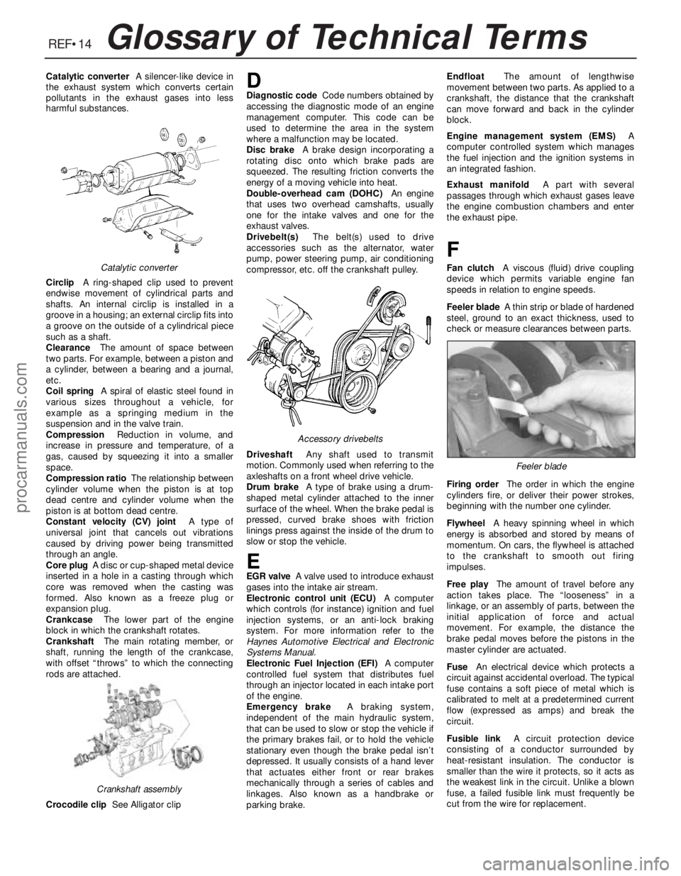
Drivebelt(s)The belt(s) used to drive
accessories such as the alternator, water
pump, power steering pump, air conditioning
compressor, etc. off the crankshaft pulley.
DriveshaftAny shaft used to transmit
motion. Commonly used when referring to the
axleshafts on a front wheel drive vehicle.
Drum brakeA type of brake using a drum-
shaped metal cylinder attached to the inner
surface of the wheel. When the brake pedal is
pressed, curved brake shoes with friction
linings press against the inside of the drum to
slow or stop the vehicle.
EEGR valveA valve used to introduce exhaust
gases into the intake air stream.
Electronic control unit (ECU)A computer
which controls (for instance) ignition and fuel
injection systems, or an anti-lock braking
system. For more information refer to the
Haynes Automotive Electrical and Electronic
Systems Manual.
Electronic Fuel Injection (EFI)A computer
controlled fuel system that distributes fuel
through an injector located in each intake port
of the engine.
Emergency brakeA braking system,
independent of the main hydraulic system,
that can be used to slow or stop the vehicle if
the primary brakes fail, or to hold the vehicle
stationary even though the brake pedal isn’t
depressed. It usually consists of a hand lever
that actuates either front or rear brakes
mechanically through a series of cables and
linkages. Also known as a handbrake or
parking brake.EndfloatThe amount of lengthwise
movement between two parts. As applied to a
crankshaft, the distance that the crankshaft
can move forward and back in the cylinder
block.
Engine management system (EMS)A
computer controlled system which manages
the fuel injection and the ignition systems in
an integrated fashion.
Exhaust manifoldA part with several
passages through which exhaust gases leave
the engine combustion chambers and enter
the exhaust pipe.
F
Fan clutchA viscous (fluid) drive coupling
device which permits variable engine fan
speeds in relation to engine speeds.
Feeler bladeA thin strip or blade of hardened
steel, ground to an exact thickness, used to
check or measure clearances between parts.
Firing orderThe order in which the engine
cylinders fire, or deliver their power strokes,
beginning with the number one cylinder.
Flywheel A heavy spinning wheel in which
energy is absorbed and stored by means of
momentum. On cars, the flywheel is attached
to the crankshaft to smooth out firing
impulses.
Free playThe amount of travel before any
action takes place. The “looseness” in a
linkage, or an assembly of parts, between the
initial application of force and actual
movement. For example, the distance the
brake pedal moves before the pistons in the
master cylinder are actuated.
FuseAn electrical device which protects a
circuit against accidental overload. The typical
fuse contains a soft piece of metal which is
calibrated to melt at a predetermined current
flow (expressed as amps) and break the
circuit.
Fusible linkA circuit protection device
consisting of a conductor surrounded by
heat-resistant insulation. The conductor is
smaller than the wire it protects, so it acts as
the weakest link in the circuit. Unlike a blown
fuse, a failed fusible link must frequently be
cut from the wire for replacement.Catalytic converter
Crankshaft assembly
Accessory drivebelts
Feeler blade
procarmanuals.com
Page 275 of 279
REF•16Glossary of Technical Terms
RotorIn a distributor, the rotating device
inside the cap that connects the centre
electrode and the outer terminals as it turns,
distributing the high voltage from the coil
secondary winding to the proper spark plug.
Also, that part of an alternator which rotates
inside the stator. Also, the rotating assembly
of a turbocharger, including the compressor
wheel, shaft and turbine wheel.
RunoutThe amount of wobble (in-and-out
movement) of a gear or wheel as it’s rotated.
The amount a shaft rotates “out-of-true.” The
out-of-round condition of a rotating part.
SSealantA liquid or paste used to prevent
leakage at a joint. Sometimes used in
conjunction with a gasket.
Sealed beam lampAn older headlight design
which integrates the reflector, lens and
filaments into a hermetically-sealed one-piece
unit. When a filament burns out or the lens
cracks, the entire unit is simply replaced.
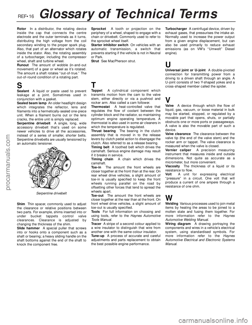
Serpentine drivebeltA single, long, wide
accessory drivebelt that’s used on some
newer vehicles to drive all the accessories,
instead of a series of smaller, shorter belts.
Serpentine drivebelts are usually tensioned by
an automatic tensioner.
ShimThin spacer, commonly used to adjust
the clearance or relative positions between
two parts. For example, shims inserted into or
under bucket tappets control valve
clearances. Clearance is adjusted by
changing the thickness of the shim.
Slide hammerA special puller that screws
into or hooks onto a component such as a
shaft or bearing; a heavy sliding handle on the
shaft bottoms against the end of the shaft to
knock the component free.SprocketA tooth or projection on the
periphery of a wheel, shaped to engage with a
chain or drivebelt. Commonly used to refer to
the sprocket wheel itself.
Starter inhibitor switchOn vehicles with an
automatic transmission, a switch that
prevents starting if the vehicle is not in Neutral
or Park.
StrutSee MacPherson strut.
TTappetA cylindrical component which
transmits motion from the cam to the valve
stem, either directly or via a pushrod and
rocker arm. Also called a cam follower.
ThermostatA heat-controlled valve that
regulates the flow of coolant between the
cylinder block and the radiator, so maintaining
optimum engine operating temperature. A
thermostat is also used in some air cleaners in
which the temperature is regulated.
Thrust bearingThe bearing in the clutch
assembly that is moved in to the release
levers by clutch pedal action to disengage the
clutch. Also referred to as a release bearing.
Timing beltA toothed belt which drives the
camshaft. Serious engine damage may result
if it breaks in service.
Timing chainA chain which drives the
camshaft.
Toe-inThe amount the front wheels are
closer together at the front than at the rear. On
rear wheel drive vehicles, a slight amount of
toe-in is usually specified to keep the front
wheels running parallel on the road by
offsetting other forces that tend to spread the
wheels apart.
Toe-outThe amount the front wheels are
closer together at the rear than at the front. On
front wheel drive vehicles, a slight amount of
toe-out is usually specified.
ToolsFor full information on choosing and
using tools, refer to the Haynes Automotive
Tools Manual.
TracerA stripe of a second colour applied to
a wire insulator to distinguish that wire from
another one with the same colour insulator.
Tune-upA process of accurate and careful
adjustments and parts replacement to obtain
the best possible engine performance.TurbochargerA centrifugal device, driven by
exhaust gases, that pressurises the intake air.
Normally used to increase the power output
from a given engine displacement, but can
also be used primarily to reduce exhaust
emissions (as on VW’s “Umwelt” Diesel
engine).
UUniversal joint or U-jointA double-pivoted
connection for transmitting power from a
driving to a driven shaft through an angle. A
U-joint consists of two Y-shaped yokes and a
cross-shaped member called the spider.
VValveA device through which the flow of
liquid, gas, vacuum, or loose material in bulk
may be started, stopped, or regulated by a
movable part that opens, shuts, or partially
obstructs one or more ports or passageways.
A valve is also the movable part of such a
device.
Valve clearanceThe clearance between the
valve tip (the end of the valve stem) and the
rocker arm or tappet. The valve clearance is
measured when the valve is closed.
Vernier caliperA precision measuring
instrument that measures inside and outside
dimensions. Not quite as accurate as a
micrometer, but more convenient.
ViscosityThe thickness of a liquid or its
resistance to flow.
VoltA unit for expressing electrical
“pressure” in a circuit. One volt that will
produce a current of one ampere through a
resistance of one ohm.
WWeldingVarious processes used to join metal
items by heating the areas to be joined to a
molten state and fusing them together. For
more information refer to the Haynes
Automotive Welding Manual.
Wiring diagramA drawing portraying the
components and wires in a vehicle’s electrical
system, using standardised symbols. For
more information refer to the Haynes
Automotive Electrical and Electronic Systems
Manual.
Serpentine drivebelt
procarmanuals.com