1993 FORD MONDEO battery
[x] Cancel search: batteryPage 221 of 279
switches mounted in the engine compartment
with a control cable connected to the throttle
valve actuator, driver-operated switches,
brake and clutch pedal switches, an indicator
light, and a road speed sensor.
4The driver-operated switches are mounted
on the steering wheel, and allow the driver to
control the various functions.
5The vehicle speed sensor uses the
speedometer cable drive pinion to generate
pulses which are fed to the speed control unit.
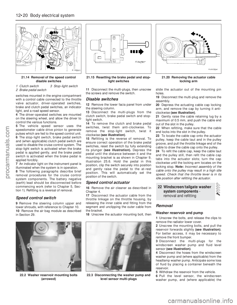
6The stop-light switch, brake pedal switch
and (when applicable) clutch pedal switch are
used to disable the cruise control system. The
stop-light switch is activated when the brake
pedal is applied gently, and the brake pedal
switch is activated when the brake pedal is
applied forcibly.
7An indicator light on the instrument panel is
illuminated when the system is in operation.
8The following paragraphs describe brief
removal procedures for the cruise control
system components. The battery negative
(earth) lead should be disconnected before
commencing work (refer to Chapter 5, Sec-
tion 1). Refitting is a reversal of removal.
Speed control switch
9Remove the steering column upper and
lower shrouds, with reference to Chapter 10.
10Remove the air bag module as described
in Section 29.11Disconnect the multi-plugs, then unscrew
the screws and remove the switch.
Disable switches
12Remove the lower facia panel from under
the steering column.
13Disconnect the multi-plugs from the
clutch switch, brake pedal switch and stop-
light switch.
14To remove the clutch and brake pedal
switches, twist them anti-clockwise. To
remove the stop-light switch, twist it
clockwise (see illustration).
15Refitting is the reverse of removal. To
ensure correct operation of the brake pedal
switches, reset the switch by fully extending
its plunger (see illustration).Depress the
pedal until the distance between it and the
mounting bracket is as shown in Chapter 9,
illustration 25.6. Hold the pedal in this
position, clip the switch securely into position
and gently raise the pedal to the at-rest
position. This will automatically set the
position of the switch.
Speed control actuator
16Remove the air cleaner as described in
Chapter 4.
17Disconnect the actuator cable from the
throttle linkage on the throttle housing, by
releasing the inner cable end fitting from the
segment and unclipping the outer cable from
the bracket.
18Unscrew the actuator mounting bolt, thenslide the actuator out of the mounting pin
holes.
19Disconnect the multi-plug and remove the
assembly.
20Depress the actuating cable cap locking
arm, and remove the cap by turning it anti-
clockwise (see illustration).
21Gently raise the cable retaining lug by a
maximum of 0.5 mm, and push the cable end
out of the slot in the pulley.
22When refitting, make sure that the cable
end locks into the slot in the pulley.
23To locate the cable cap onto the actuator
pulley, keep the cable taut and in the pulley
groove, and pull the throttle linkage end of the
cable to draw the cable cap onto the pulley.
24To refit the cable cap, keep the cable taut
and the pulley still, then refit the cable cap
tabs into the actuator slots; turn the cap
clockwise until the locking arm locates on the
locking stop. Note:Incorrect assembly of the
cable onto the pulley may result in a high idle
speed. Check that the throttle lever is in its
idle position after refitting the actuator.
Removal
Washer reservoir and pump
1Unscrew the bolts, and release the clips to
remove the radiator lower cover.
2Unscrew the mounting bolts, and pull the
reservoir forwards slightly (see illustration).
For better access, it may be necessary to
remove the front bumper.
3Disconnect the multi-plugs for the
windscreen washer pump and fluid level
sensor (see illustration).
4Disconnect the hoses from the windscreen
washer pump and (where applicable) from the
headlamp washer pump. Anticipate some loss
of fluid by placing a container beneath the
reservoir.
5Withdraw the reservoir from the vehicle.
6Pull the level sensor, the windscreen
washer pump, and (where applicable) the
22 Windscreen/tailgate washer
system components -
removal and refitting
12•20 Body electrical system
21.14 Removal of the speed control
disable switches
1 Clutch switch 3 Stop-light switch
2 Brake pedal switch21.15 Resetting the brake pedal and stop-
light switches21.20 Removing the actuator cable
locking arm
22.2 Washer reservoir mounting bolts
(arrowed)22.3 Disconnecting the washer pump and
level sensor multi-plugs
procarmanuals.com
Page 222 of 279
headlamp washer pump, from the reservoir
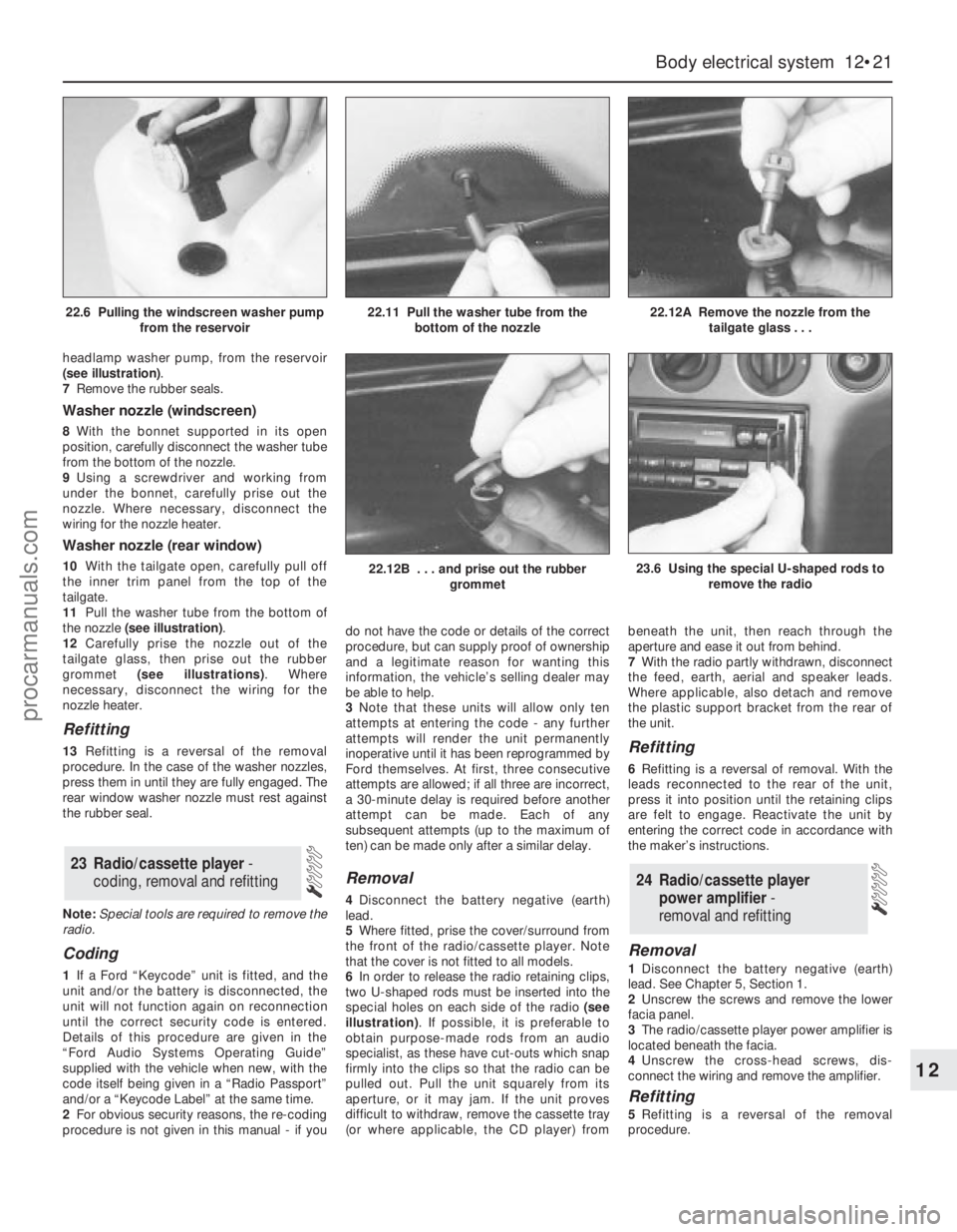
(see illustration).
7Remove the rubber seals.
Washer nozzle (windscreen)
8With the bonnet supported in its open
position, carefully disconnect the washer tube
from the bottom of the nozzle.
9Using a screwdriver and working from
under the bonnet, carefully prise out the
nozzle. Where necessary, disconnect the
wiring for the nozzle heater.
Washer nozzle (rear window)
10With the tailgate open, carefully pull off
the inner trim panel from the top of the
tailgate.
11Pull the washer tube from the bottom of
the nozzle (see illustration).
12Carefully prise the nozzle out of the
tailgate glass, then prise out the rubber
grommet (see illustrations). Where
necessary, disconnect the wiring for the
nozzle heater.
Refitting
13Refitting is a reversal of the removal
procedure. In the case of the washer nozzles,
press them in until they are fully engaged. The
rear window washer nozzle must rest against
the rubber seal.
Note:Special tools are required to remove the
radio.
Coding
1If a Ford “Keycode” unit is fitted, and the
unit and/or the battery is disconnected, the
unit will not function again on reconnection
until the correct security code is entered.
Details of this procedure are given in the
“Ford Audio Systems Operating Guide”
supplied with the vehicle when new, with the
code itself being given in a “Radio Passport”
and/or a “Keycode Label” at the same time.
2For obvious security reasons, the re-coding
procedure is not given in this manual - if youdo not have the code or details of the correct
procedure, but can supply proof of ownership
and a legitimate reason for wanting this
information, the vehicle’s selling dealer may
be able to help.
3Note that these units will allow only ten
attempts at entering the code - any further
attempts will render the unit permanently
inoperative until it has been reprogrammed by
Ford themselves. At first, three consecutive
attempts are allowed; if all three are incorrect,
a 30-minute delay is required before another
attempt can be made. Each of any
subsequent attempts (up to the maximum of
ten) can be made only after a similar delay.
Removal
4Disconnect the battery negative (earth)
lead.
5Where fitted, prise the cover/surround from
the front of the radio/cassette player. Note
that the cover is not fitted to all models.
6In order to release the radio retaining clips,
two U-shaped rods must be inserted into the
special holes on each side of the radio (see
illustration). If possible, it is preferable to
obtain purpose-made rods from an audio
specialist, as these have cut-outs which snap
firmly into the clips so that the radio can be
pulled out. Pull the unit squarely from its
aperture, or it may jam. If the unit proves
difficult to withdraw, remove the cassette tray
(or where applicable, the CD player) frombeneath the unit, then reach through the
aperture and ease it out from behind.
7With the radio partly withdrawn, disconnect
the feed, earth, aerial and speaker leads.
Where applicable, also detach and remove
the plastic support bracket from the rear of
the unit.
Refitting
6Refitting is a reversal of removal. With the
leads reconnected to the rear of the unit,
press it into position until the retaining clips
are felt to engage. Reactivate the unit by
entering the correct code in accordance with
the maker’s instructions.
Removal
1Disconnect the battery negative (earth)
lead. See Chapter 5, Section 1.
2Unscrew the screws and remove the lower
facia panel.
3The radio/cassette player power amplifier is
located beneath the facia.
4Unscrew the cross-head screws, dis-
connect the wiring and remove the amplifier.
Refitting
5Refitting is a reversal of the removal
procedure.
24 Radio/cassette player
power amplifier -
removal and refitting
23 Radio/cassette player -
coding, removal and refitting
Body electrical system 12•21
12
22.12B . . . and prise out the rubber
grommet23.6 Using the special U-shaped rods to
remove the radio
22.6 Pulling the windscreen washer pump
from the reservoir22.11 Pull the washer tube from the
bottom of the nozzle22.12A Remove the nozzle from the
tailgate glass . . .
procarmanuals.com
Page 223 of 279
1A compact disc (CD) player is available as
an optional extra on most models. On some
models, an autochanger version is available,
which can hold a number of discs at a time.
Removal
2The battery negative (earth) lead should be
disconnected before commencing work.
CD player, or autochanger control
unit
3The procedure is identical to that for the
radio/cassette player described in Section 23.
CD player autochanger
4The CD player autochanger unit is mounted
on the right-hand side of the luggage
compartment. The wiring loom passes up the
“C” pillar, across to the left-hand side “A”
pillar, then to the centre console area.
5Remove the trim cover from the
autochanger unit.
6Unscrew the mounting screws, and remove
the autochanger unit from its mounting
bracket.
7Disconnect the multi-plug and remove the
unit from inside the vehicle.
Refitting
8Refitting is a reversal of the removal
procedure.
Removal
1Remove the door trim panel as described in
Chapter 11.
2Unscrew the cross-head screws, and
withdraw the speaker from the door inner
panel.
3Disconnect the wiring and remove the
speaker.
Refitting
4Refitting is a reversal of the removal
procedure.
Removal
1Prise out the trim cover from the headlining
immediately below the base of the aerial.
2Unscrew the cross-head screw from the
base of the aerial, and remove the aerial mast.
Refitting
3Refitting is a reversal of the removal
procedure.
Warning: Handle the air bag unit
with extreme care, as a
precaution against personal
injury, and always hold it with the
cover facing away from the body. If in
doubt concerning any proposed work
involving the air bag unit or its control
circuitry, consult a Ford dealer or other
qualified specialist.
Removal
1Disconnect the battery negative (earth) lead
(refer to Chapter 5, Section 1).
Warning: Before proceeding, wait
a minimum of 15 minutes, as a
precaution against accidental
firing of the air bag unit. This
period ensures that any stored energy in
the back-up capacitor is dissipated.
2Rotate the steering wheel so that one of the
mounting bolt holes is visible above the
steering column upper shroud.
3Unscrew and remove the first mounting
bolt, then turn the steering wheel as
necessary and remove the remaining
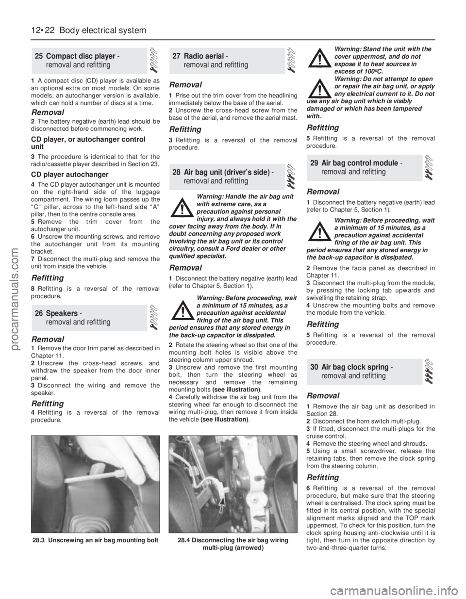
mounting bolts (see illustration).
4Carefully withdraw the air bag unit from the
steering wheel far enough to disconnect the
wiring multi-plug, then remove it from inside
the vehicle (see illustration). Warning: Stand the unit with the
cover uppermost, and do not
expose it to heat sources in
excess of 100ºC.
Warning: Do not attempt to open
or repair the air bag unit, or apply
any electrical current to it. Do not
use any air bag unit which is visibly
damaged or which has been tampered
with.
Refitting
5Refitting is a reversal of the removal
procedure.
Removal
1Disconnect the battery negative (earth) lead
(refer to Chapter 5, Section 1).
Warning: Before proceeding, wait
a minimum of 15 minutes, as a
precaution against accidental
firing of the air bag unit. This
period ensures that any stored energy in
the back-up capacitor is dissipated.
2Remove the facia panel as described in
Chapter 11.
3Disconnect the multi-plug from the module,
by pressing the locking tab upwards and
swivelling the retaining strap.
4Unscrew the mounting bolts and remove
the module from the vehicle.
Refitting
5Refitting is a reversal of the removal
procedure.
Removal
1Remove the air bag unit as described in
Section 28.
2Disconnect the horn switch multi-plug.
3If fitted, disconnect the multi-plugs for the
cruise control.
4Remove the steering wheel and shrouds.
5Using a small screwdriver, release the
retaining tabs, then remove the clock spring
from the steering column.
Refitting
6Refitting is a reversal of the removal
procedure, but make sure that the steering
wheel is centralised. The clock spring must be
fitted in its central position, with the special
alignment marks aligned and the TOP mark
uppermost. To check for this position, turn the
clock spring housing anti-clockwise until it is
tight, then turn in the opposite direction by
two-and-three-quarter turns.
30 Air bag clock spring-
removal and refitting
29 Air bag control module -
removal and refitting
28 Air bag unit (driver’s side) -
removal and refitting
27 Radio aerial -
removal and refitting
26 Speakers -
removal and refitting
25 Compact disc player -
removal and refitting
12•22 Body electrical system
28.3 Unscrewing an air bag mounting bolt28.4 Disconnecting the air bag wiring
multi-plug (arrowed)
procarmanuals.com
Page 265 of 279
REF•6Fault Finding
Engine 1
m mEngine backfires
m mEngine difficult to start when cold
m mEngine difficult to start when hot
m mEngine fails to rotate when attempting to start
m mEngine hesitates on acceleration
m mEngine idles erratically
m mEngine lacks power
m mEngine misfires at idle speed
m mEngine misfires throughout the driving speed range
m mEngine noises
m mEngine rotates but will not start
m mEngine runs-on after switching off
m mEngine stalls
m mEngine starts but stops immediately
m mOil pressure warning light illuminated with engine running
m mStarter motor noisy or excessively-rough in engagement
Cooling system 2
m
mCorrosion
m mExternal coolant leakage
m mInternal coolant leakage
m mOvercooling
m mOverheating
Fuel and exhaust systems 3
m
mExcessive fuel consumption
m mExcessive noise or fumes from exhaust system
m mFuel leakage and/or fuel odour
Clutch 4
m
mClutch fails to disengage (unable to select gears)
m mClutch slips (engine speed increases with no increase
in vehicle speed)
m mJudder as clutch is engaged
m mNoise when depressing or releasing clutch pedal
m mPedal travels to floor - no pressure or very little resistance
Manual transmission 5
m
mJumps out of gear
m mLubricant leaks
m mNoisy in neutral with engine running
m mNoisy in one particular gear
m mVibration
Automatic transmission 6
m
mEngine will not start in any gear, or starts in gears
other than Park or Neutral
m mFluid leakage
m mGeneral gear selection problems
m mTransmission fluid brown, or has burned smell
m mTransmission slips, shifts roughly, is noisy, or
has no drive in forward or reverse gears
m mTransmission will not downshift (kickdown) with
accelerator fully depressed
Driveshafts 7
m mClicking or knocking noise on turns (at slow speed on full-lock)
m mVibration when accelerating or decelerating
Braking system 8
m
mBrake pedal feels spongy when depressed
m mBrakes binding
m mExcessive brake pedal effort required to stop vehicle
m mExcessive brake pedal travel
m mJudder felt through brake pedal or steering wheel when braking
m mNoise (grinding or high-pitched squeal) when brakes applied
m mRear wheels locking under normal braking
m mVehicle pulls to one side under braking
Suspension and steering systems 9
m
mExcessive pitching and/or rolling around corners, or during
braking
m mExcessive play in steering
m mExcessively-stiff steering
m mLack of power assistance
m mTyre wear excessive
m mVehicle pulls to one side
m mWandering or general instability
m mWheel wobble and vibration
Electrical system 10
m
mBattery will not hold a charge for more than a few days
m mCentral locking system inoperative, or unsatisfactory in operation
m mElectric windows inoperative, or unsatisfactory in operation
m mHorn inoperative, or unsatisfactory in operation
m mIgnition warning light fails to come on
m mIgnition warning light remains illuminated with engine running
m mInstrument readings inaccurate or erratic
m mLights inoperative
m mWindscreen/tailgate washers inoperative, or unsatisfactory in
operation
m mWindscreen/tailgate wipers inoperative, or unsatisfactory in
operation
procarmanuals.com
Page 266 of 279
REF•7
Engine fails to rotate when attempting to start
m mBattery terminal connections loose or corroded (Chapter 5).
m mBattery discharged or faulty (Chapter 5).
m mBroken, loose or disconnected wiring in the starting circuit
(Chapter 5).
m mDefective starter solenoid or switch (Chapter 5).
m mDefective starter motor (Chapter 5).
m mStarter pinion or flywheel ring gear teeth loose or broken (Chap-
ter 5).
m mEngine earth strap broken or disconnected (Chapter 5).
m mAutomatic transmission not in Park/Neutral position, or selector
lever position sensor faulty (Chapter 7, Part B).
Engine rotates but will not start
m mFuel tank empty.
m mBattery discharged (engine rotates slowly) (Chapter 5).
m mBattery terminal connections loose or corroded (Chapter 5).
m mIgnition components damp or damaged (Chapters 1 and 5).
m mBroken, loose or disconnected wiring in the ignition circuit
(Chapters 1 and 5).
m mWorn, faulty or incorrectly-gapped spark plugs (Chapter 1).
m mMajor mechanical failure (eg camshaft drive) (Chapter 2, Part A).
Engine difficult to start when cold
m
mBattery discharged (Chapter 5).
m mBattery terminal connections loose or corroded (Chapter 5).
m mWorn, faulty or incorrectly-gapped spark plugs (Chapter 1).
m mOther ignition system fault (Chapters 1 and 5).
m mEngine management system fault (Chapters 1, 4, 5 and 6)
m mLow cylinder compressions (Chapter 2, Part A).
Engine difficult to start when hot
m
mAir filter element dirty or clogged (Chapter 1).
m mEngine management system fault (Chapters 1, 4, 5 and 6)
m mLow cylinder compressions (Chapter 2, Part A).
m mFaulty hydraulic tappet(s) (Chapter 2, Part A).
Starter motor noisy or excessively-rough in
engagement
m mStarter pinion or flywheel ring gear teeth loose or broken (Chapter 5).
m mStarter motor mounting bolts loose or missing (Chapter 5).
m mStarter motor internal components worn or damaged (Chapter 5).
Engine starts but stops immediately
m
mLoose or faulty electrical connections in the ignition circuit
(Chapters 1 and 5).
m mEngine management system fault (Chapters 1, 4, 5 and 6)
m mVacuum leak at the inlet manifold (Chapters 1, 4 and 6).
Engine idles erratically
m
mIdle speed control valve faulty (Chapter 4).
m mEngine management system fault (Chapters 1, 4, 5 and 6)
m mAir filter element clogged (Chapter 1).
m mVacuum leak at the inlet manifold or associated hoses (Chap-
ters 1, 4 and 6).
m mWorn, faulty or incorrectly-gapped spark plugs (Chapter 1).
m mFaulty hydraulic tappet(s) (Chapter 2, Part A).
m mUneven or low cylinder compressions (Chapter 2, Part A).
m mCamshaft lobes worn (Chapter 2).
m mTiming belt incorrectly-tensioned (Chapter 2, Part A).
Engine misfires at idle speed
m
mWorn, faulty or incorrectly-gapped spark plugs (Chapter 1).
m mFaulty spark plug HT leads (Chapter 1).
m mIdle speed control valve faulty (Chapter 4).
m mIncorrect ignition timing (Chapters 5 and 6).
m mEngine management system fault (Chapters 1, 4, 5 and 6)
m mVacuum leak at the inlet manifold or associated hoses (Chap-
ters 1, 4 and 6).
m mFaulty hydraulic tappet(s) (Chapter 2, Part A).
m mUneven or low cylinder compressions (Chapter 2, Part A).
m mDisconnected, leaking or perished crankcase ventilation hoses
(Chapters 1 and 6).
Fault Finding
The vehicle owner who does his or her own maintenance according
to the recommended service schedules should not have to use this
section of the manual very often. Modern component reliability is such
that, provided those items subject to wear or deterioration are inspected
or renewed at the specified intervals, sudden failure is comparatively
rare. Faults do not usually just happen as a result of sudden failure, but
develop over a period of time. Major mechanical failures in particular are
usually preceded by characteristic symptoms over hundreds or even
thousands of miles. Those components which do occasionally fail
without warning are often small and easily carried in the vehicle.
With any fault-finding, the first step is to decide where to begin
investigations. Sometimes this is obvious, but on other occasions, a
little detective work will be necessary. The owner who makes half a
dozen haphazard adjustments or replacements may be successful in
curing a fault (or its symptoms), but will be none the wiser if the fault
recurs, and ultimately may have spent more time and money than was
necessary. A calm and logical approach will be found to be more
satisfactory in the long run. Always take into account any warning
signs or abnormalities that may have been noticed in the period
preceding the fault - power loss, high or low gauge readings, unusual
smells, etc - and remember that failure of components such as fuses
or spark plugs may only be pointers to some underlying fault.
The pages which follow provide an easy reference guide to the
more common problems which may occur during the operation of the
vehicle. These problems and their possible causes are grouped underheadings denoting various components or systems, such as Engine,
Cooling system, etc. The Chapter and/or Section which deals with the
problem is also shown in brackets. Whatever the fault, certain basic
principles apply. These are as follows:
Verify the fault. This is simply a matter of being sure that you know
what the symptoms are before starting work. This is particularly
important if you are investigating a fault for someone else, who may
not have described it very accurately.
Don’t overlook the obvious. For example, if the vehicle won’t start, is
there petrol in the tank? (Don’t take anyone else’s word on this
particular point, and don’t trust the fuel gauge either!) If an electrical
fault is indicated, look for loose or broken wires before digging out the
test gear.
Cure the disease, not the symptom. Substituting a flat battery with a
fully-charged one will get you off the hard shoulder, but if the underlying
cause is not attended to, the new battery will go the same way. Similarly,
changing oil-fouled spark plugs for a new set will get you moving again,
but remember that the reason for the fouling (if it wasn’t simply an
incorrect grade of plug) will have to be established and corrected.
Don’t take anything for granted. Particularly, don’t forget that a
“new” component may itself be defective (especially if it’s been
rattling around in the boot for months), and don’t leave components
out of a fault diagnosis sequence just because they are new or
recently fitted. When you do finally diagnose a difficult fault, you’ll
probably realise that all the evidence was there from the start.
1 Engine
Introduction
procarmanuals.com
Page 271 of 279
REF•12
Battery will not hold a charge more than a few days
m mBattery defective internally (Chapter 5).
m mBattery electrolyte level low (Chapter 1).
m mBattery terminal connections loose or corroded (Chapter 5).
m mAuxiliary drivebelt worn or incorrectly-adjusted (Chapter 1).
m mAlternator not charging at correct output (Chapter 5).
m mAlternator or voltage regulator faulty (Chapter 5).
m mShort-circuit causing continual battery drain (Chapters 5 and 12).
Ignition (no-charge) warning light remains
illuminated with engine running
m mAuxiliary drivebelt broken, worn, or incorrectly-adjusted (Chapter 1).
m mAlternator brushes worn, sticking, or dirty (Chapter 5).
m mAlternator brush springs weak or broken (Chapter 5).
m mInternal fault in alternator or voltage regulator (Chapter 5).
m mBroken, disconnected, or loose wiring in charging circuit (Chapter 5).
Ignition (no-charge) warning light fails to come on
m
mWarning light bulb blown (Chapter 12).
m mBroken, disconnected, or loose wiring in warning light circuit
(Chapters 5 and 12).
m mAlternator faulty (Chapter 5).
Lights inoperative
m
mBulb blown (Chapter 12).
m mCorrosion of bulb or bulbholder contacts (Chapter 12).
m mBlown fuse (Chapter 12).
m mFaulty relay (Chapter 12).
m mBroken, loose, or disconnected wiring (Chapter 12).
m mFaulty switch (Chapter 12).
Instrument readings inaccurate or erratic
Instrument readings increase with engine speed
m
mFaulty voltage regulator (Chapter 12).
Fuel or temperature gauges give no reading
m
mFaulty gauge sender unit (Chapters 3 or 4).
m mWiring open-circuit (Chapter 12).
m mFaulty gauge (Chapter 12).
Fuel or temperature gauges give continuous maximum reading
m mFaulty gauge sender unit (Chapters 3 or 4).
m mWiring short-circuit (Chapter 12).
m mFaulty gauge (Chapter 12).
Horn inoperative, or unsatisfactory in operation
Horn fails to operate
m
mBlown fuse (Chapter 12).
m mCable or cable connections loose, broken or disconnected (Chapter 12).
m mFaulty horn (Chapter 12).
Horn emits intermittent or unsatisfactory sound
m
mCable connections loose (Chapter 12).
m mHorn mountings loose (Chapter 12).
m mFaulty horn (Chapter 12).
Horn operates all the time
m
mHorn push either earthed or stuck down (Chapter 12).
m mHorn cable to horn push earthed (Chapter 12).
Windscreen/tailgate wipers inoperative or
unsatisfactory in operation
Wipers fail to operate, or operate very slowly
m mWiper blades stuck to screen, or linkage seized or binding (Chapter 12).
m mBlown fuse (Chapter 12).
m mCable or cable connections loose, broken or disconnected (Chapter 12).
m mFaulty relay (Chapter 12).
m mFaulty wiper motor (Chapter 12).
Wiper blades sweep over too large or too small an area of
the glass
m mWiper arms incorrectly-positioned on spindles (Chapter 1).
m mExcessive wear of wiper linkage (Chapter 1).
m mWiper motor or linkage mountings loose or insecure (Chapter 12).
Wiper blades fail to clean the glass effectively
m
mWiper blade rubbers worn or perished (Chapter 1).
m mWiper arm tension springs broken, or arm pivots seized (Chapter 1).
m mInsufficient windscreen washer additive to adequately remove road
film (Chapter 1).
Windscreen/tailgate washers inoperative, or
unsatisfactory in operation
One or more washer jets inoperative
m mBlocked washer jet (Chapter 1).
m mDisconnected, kinked or restricted fluid hose (Chapter 1).
m mInsufficient fluid in washer reservoir (Chapter 1).
Washer pump fails to operate
m
mBroken or disconnected wiring or connections (Chapter 12).
m mBlown fuse (Chapter 12).
m mFaulty washer switch (Chapter 12).
m mFaulty washer pump (Chapter 12).
Washer pump runs for some time before fluid is emitted
from jets
m mFaulty one-way valve in fluid supply hose (Chapter 12).
Electric windows inoperative, or unsatisfactory in
operation
Window glass will only move in one direction
m mFaulty switch (Chapter 12).
Window glass slow to move
m
mIncorrectly-adjusted door glass guide channels (Chapter 11).
m mRegulator seized or damaged, or in need of lubrication (Chapter 11).
m mDoor internal components or trim fouling regulator (Chapter 11).
m mFaulty motor (Chapter 12).
Window glass fails to move
m
mIncorrectly-adjusted door glass guide channels (Chapter 11).
m mBlown fuse (Chapter 12).
m mFaulty relay (Chapter 12).
m mBroken or disconnected wiring or connections (Chapter 12).
m mFaulty motor (Chapter 12).
Central locking system inoperative, or
unsatisfactory in operation
Complete system failure
m mBlown fuse (Chapter 12).
m mFaulty relay (Chapter 12).
m mBroken or disconnected wiring or connections (Chapter 12).
Latch locks but will not unlock, or unlocks but will not lock
m
mFaulty master switch (Chapter 11).
m mBroken or disconnected latch operating rods or levers (Chapter 11).
m mFaulty relay (Chapter 12).
One lock motor fails to operate
m
mBroken or disconnected wiring or connections (Chapter 12).
m mFaulty lock motor (Chapter 11).
m mBroken, binding or disconnected latch operating rods or levers
(Chapter 11).
m mFault in door latch (Chapter 11).
Fault Finding
10 Electrical system
Note:For problems associated with the starting system, refer to the faults listed under “Engine”earlier in this Section.
procarmanuals.com
Page 272 of 279
REF•13Glossary of Technical Terms
A
ABS (Anti-lock brake system)A system,
usually electronically controlled, that senses
incipient wheel lockup during braking and
relieves hydraulic pressure at wheels that are
about to skid.
Air bag An inflatable bag hidden in the
steering wheel (driver’s side) or the dash or
glovebox (passenger side). In a head-on
collision, the bags inflate, preventing the
driver and front passenger from being thrown
forward into the steering wheel or windscreen.
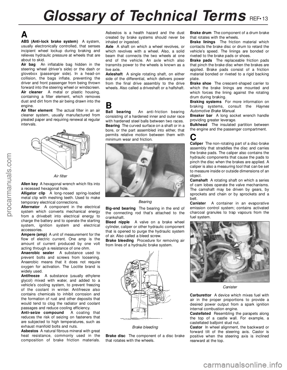
Air cleanerA metal or plastic housing,
containing a filter element, which removes
dust and dirt from the air being drawn into the
engine.
Air filter elementThe actual filter in an air
cleaner system, usually manufactured from
pleated paper and requiring renewal at regular
intervals.
Allen keyA hexagonal wrench which fits into
a recessed hexagonal hole.
Alligator clipA long-nosed spring-loaded
metal clip with meshing teeth. Used to make
temporary electrical connections.
AlternatorA component in the electrical
system which converts mechanical energy
from a drivebelt into electrical energy to
charge the battery and to operate the starting
system, ignition system and electrical
accessories.
Ampere (amp)A unit of measurement for the
flow of electric current. One amp is the
amount of current produced by one volt
acting through a resistance of one ohm.
Anaerobic sealerA substance used to
prevent bolts and screws from loosening.
Anaerobic means that it does not require
oxygen for activation. The Loctite brand is
widely used.
AntifreezeA substance (usually ethylene
glycol) mixed with water, and added to a
vehicle’s cooling system, to prevent freezing
of the coolant in winter. Antifreeze also
contains chemicals to inhibit corrosion and
the formation of rust and other deposits that
would tend to clog the radiator and coolant
passages and reduce cooling efficiency.
Anti-seize compoundA coating that
reduces the risk of seizing on fasteners that
are subjected to high temperatures, such as
exhaust manifold bolts and nuts.
AsbestosA natural fibrous mineral with great
heat resistance, commonly used in the
composition of brake friction materials.Asbestos is a health hazard and the dust
created by brake systems should never be
inhaled or ingested.
AxleA shaft on which a wheel revolves, or
which revolves with a wheel. Also, a solid
beam that connects the two wheels at one
end of the vehicle. An axle which also
transmits power to the wheels is known as a
live axle.
AxleshaftA single rotating shaft, on either
side of the differential, which delivers power
from the final drive assembly to the drive
wheels. Also called a driveshaft or a halfshaft.
BBall bearingAn anti-friction bearing
consisting of a hardened inner and outer race
with hardened steel balls between two races.
BearingThe curved surface on a shaft or in a
bore, or the part assembled into either, that
permits relative motion between them with
minimum wear and friction.
Big-end bearingThe bearing in the end of
the connecting rod that’s attached to the
crankshaft.
Bleed nippleA valve on a brake wheel
cylinder, caliper or other hydraulic component
that is opened to purge the hydraulic system
of air. Also called a bleed screw.
Brake bleedingProcedure for removing air
from lines of a hydraulic brake system.
Brake discThe component of a disc brake
that rotates with the wheels.Brake drumThe component of a drum brake
that rotates with the wheels.
Brake liningsThe friction material which
contacts the brake disc or drum to retard the
vehicle’s speed. The linings are bonded or
riveted to the brake pads or shoes.
Brake padsThe replaceable friction pads
that pinch the brake disc when the brakes are
applied. Brake pads consist of a friction
material bonded or riveted to a rigid backing
plate.
Brake shoeThe crescent-shaped carrier to
which the brake linings are mounted and
which forces the lining against the rotating
drum during braking.
Braking systemsFor more information on
braking systems, consult the Haynes
Automotive Brake Manual.
Breaker barA long socket wrench handle
providing greater leverage.
BulkheadThe insulated partition between
the engine and the passenger compartment.
CCaliperThe non-rotating part of a disc-brake
assembly that straddles the disc and carries
the brake pads. The caliper also contains the
hydraulic components that cause the pads to
pinch the disc when the brakes are applied. A
caliper is also a measuring tool that can be set
to measure inside or outside dimensions of an
object.
CamshaftA rotating shaft on which a series
of cam lobes operate the valve mechanisms.
The camshaft may be driven by gears, by
sprockets and chain or by sprockets and a
belt.
CanisterA container in an evaporative
emission control system; contains activated
charcoal granules to trap vapours from the
fuel system.
CarburettorA device which mixes fuel with
air in the proper proportions to provide a
desired power output from a spark ignition
internal combustion engine.
CastellatedResembling the parapets along
the top of a castle wall. For example, a
castellated balljoint stud nut.
CastorIn wheel alignment, the backward or
forward tilt of the steering axis. Castor is
positive when the steering axis is inclined
rearward at the top.
Canister
Brake bleeding
Bearing
Air filter
procarmanuals.com
Page 274 of 279
REF•15Glossary of Technical Terms
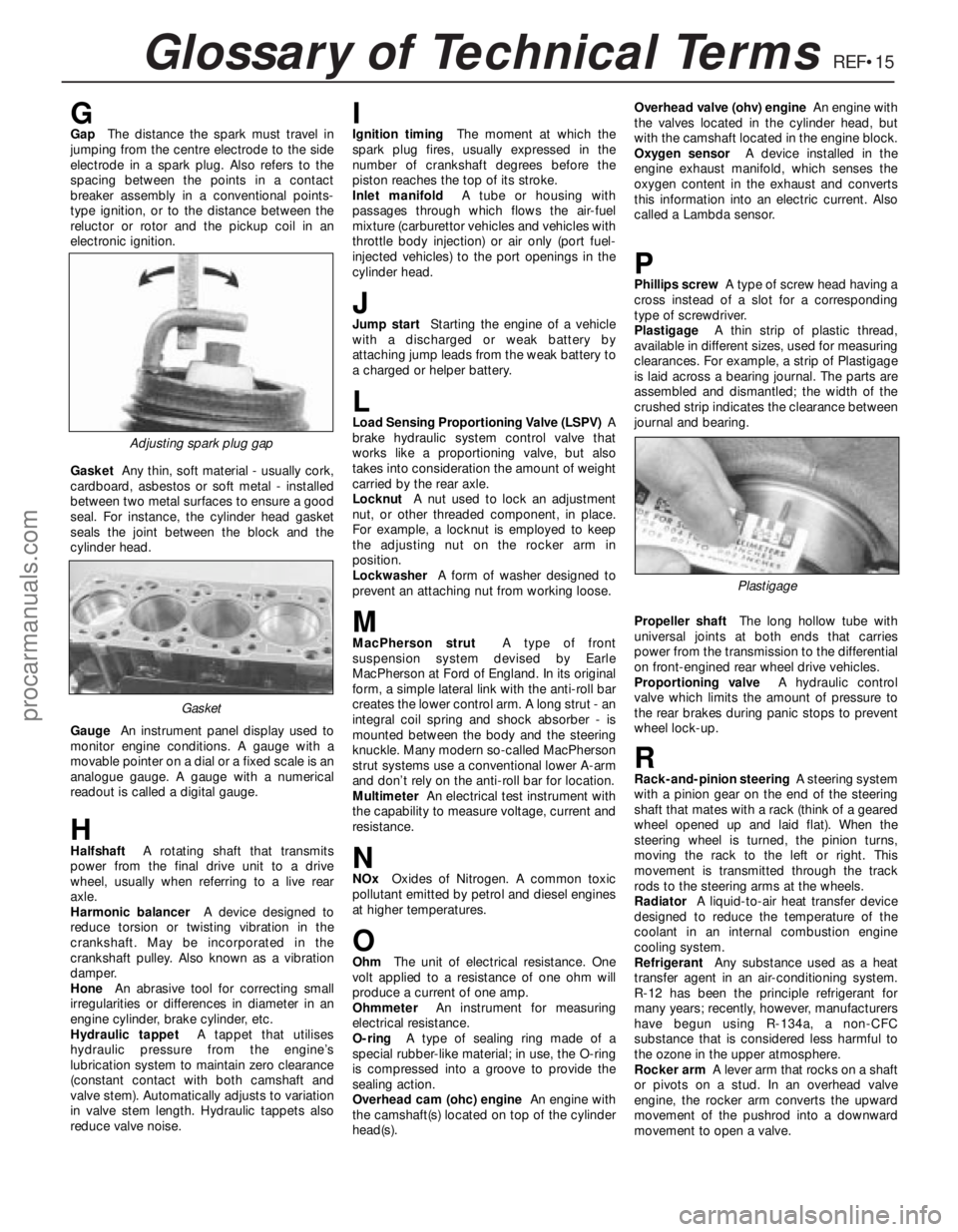
GGapThe distance the spark must travel in
jumping from the centre electrode to the side
electrode in a spark plug. Also refers to the
spacing between the points in a contact
breaker assembly in a conventional points-
type ignition, or to the distance between the
reluctor or rotor and the pickup coil in an
electronic ignition.
GasketAny thin, soft material - usually cork,
cardboard, asbestos or soft metal - installed
between two metal surfaces to ensure a good
seal. For instance, the cylinder head gasket
seals the joint between the block and the
cylinder head.
GaugeAn instrument panel display used to
monitor engine conditions. A gauge with a
movable pointer on a dial or a fixed scale is an
analogue gauge. A gauge with a numerical
readout is called a digital gauge.
HHalfshaftA rotating shaft that transmits
power from the final drive unit to a drive
wheel, usually when referring to a live rear
axle.
Harmonic balancerA device designed to
reduce torsion or twisting vibration in the
crankshaft. May be incorporated in the
crankshaft pulley. Also known as a vibration
damper.
HoneAn abrasive tool for correcting small
irregularities or differences in diameter in an
engine cylinder, brake cylinder, etc.
Hydraulic tappetA tappet that utilises
hydraulic pressure from the engine’s
lubrication system to maintain zero clearance
(constant contact with both camshaft and
valve stem). Automatically adjusts to variation
in valve stem length. Hydraulic tappets also
reduce valve noise.
IIgnition timingThe moment at which the
spark plug fires, usually expressed in the
number of crankshaft degrees before the
piston reaches the top of its stroke.
Inlet manifoldA tube or housing with
passages through which flows the air-fuel
mixture (carburettor vehicles and vehicles with
throttle body injection) or air only (port fuel-
injected vehicles) to the port openings in the
cylinder head.
JJump startStarting the engine of a vehicle
with a discharged or weak battery by
attaching jump leads from the weak battery to
a charged or helper battery.
LLoad Sensing Proportioning Valve (LSPV)A
brake hydraulic system control valve that
works like a proportioning valve, but also
takes into consideration the amount of weight
carried by the rear axle.
LocknutA nut used to lock an adjustment
nut, or other threaded component, in place.
For example, a locknut is employed to keep
the adjusting nut on the rocker arm in
position.
LockwasherA form of washer designed to
prevent an attaching nut from working loose.
MMacPherson strutA type of front
suspension system devised by Earle
MacPherson at Ford of England. In its original
form, a simple lateral link with the anti-roll bar
creates the lower control arm. A long strut - an
integral coil spring and shock absorber - is
mounted between the body and the steering
knuckle. Many modern so-called MacPherson
strut systems use a conventional lower A-arm
and don’t rely on the anti-roll bar for location.
MultimeterAn electrical test instrument with
the capability to measure voltage, current and
resistance.
NNOxOxides of Nitrogen. A common toxic
pollutant emitted by petrol and diesel engines
at higher temperatures.
OOhmThe unit of electrical resistance. One
volt applied to a resistance of one ohm will
produce a current of one amp.
OhmmeterAn instrument for measuring
electrical resistance.
O-ringA type of sealing ring made of a
special rubber-like material; in use, the O-ring
is compressed into a groove to provide the
sealing action.
Overhead cam (ohc) engineAn engine with
the camshaft(s) located on top of the cylinder
head(s).Overhead valve (ohv) engineAn engine with
the valves located in the cylinder head, but
with the camshaft located in the engine block.
Oxygen sensorA device installed in the
engine exhaust manifold, which senses the
oxygen content in the exhaust and converts
this information into an electric current. Also
called a Lambda sensor.
PPhillips screwA type of screw head having a
cross instead of a slot for a corresponding
type of screwdriver.
PlastigageA thin strip of plastic thread,
available in different sizes, used for measuring
clearances. For example, a strip of Plastigage
is laid across a bearing journal. The parts are
assembled and dismantled; the width of the
crushed strip indicates the clearance between
journal and bearing.
Propeller shaftThe long hollow tube with
universal joints at both ends that carries
power from the transmission to the differential
on front-engined rear wheel drive vehicles.
Proportioning valveA hydraulic control
valve which limits the amount of pressure to
the rear brakes during panic stops to prevent
wheel lock-up.
RRack-and-pinion steeringA steering system
with a pinion gear on the end of the steering
shaft that mates with a rack (think of a geared
wheel opened up and laid flat). When the
steering wheel is turned, the pinion turns,
moving the rack to the left or right. This
movement is transmitted through the track
rods to the steering arms at the wheels.
RadiatorA liquid-to-air heat transfer device
designed to reduce the temperature of the
coolant in an internal combustion engine
cooling system.
RefrigerantAny substance used as a heat
transfer agent in an air-conditioning system.
R-12 has been the principle refrigerant for
many years; recently, however, manufacturers
have begun using R-134a, a non-CFC
substance that is considered less harmful to
the ozone in the upper atmosphere.
Rocker armA lever arm that rocks on a shaft
or pivots on a stud. In an overhead valve
engine, the rocker arm converts the upward
movement of the pushrod into a downward
movement to open a valve.
Adjusting spark plug gap
Plastigage
Gasket
procarmanuals.com