1993 DODGE TRUCK fuel rail
[x] Cancel search: fuel railPage 860 of 1502
•
FUEL
SYSTEM
14 - 41
THROTTLE
BODY
FUEL
RAIL
CONNECTING
HOSES
THROTTLE
BODY
MOUNTING
BOLTS
J9214-31
Fig.
18
Throttle
Body
MOUNTING
SCREWS
MAP
SENSOR
RUBBER
FITTING
J9314-87
Fig.
19 Air Control
Passage
FUEL
RAIL
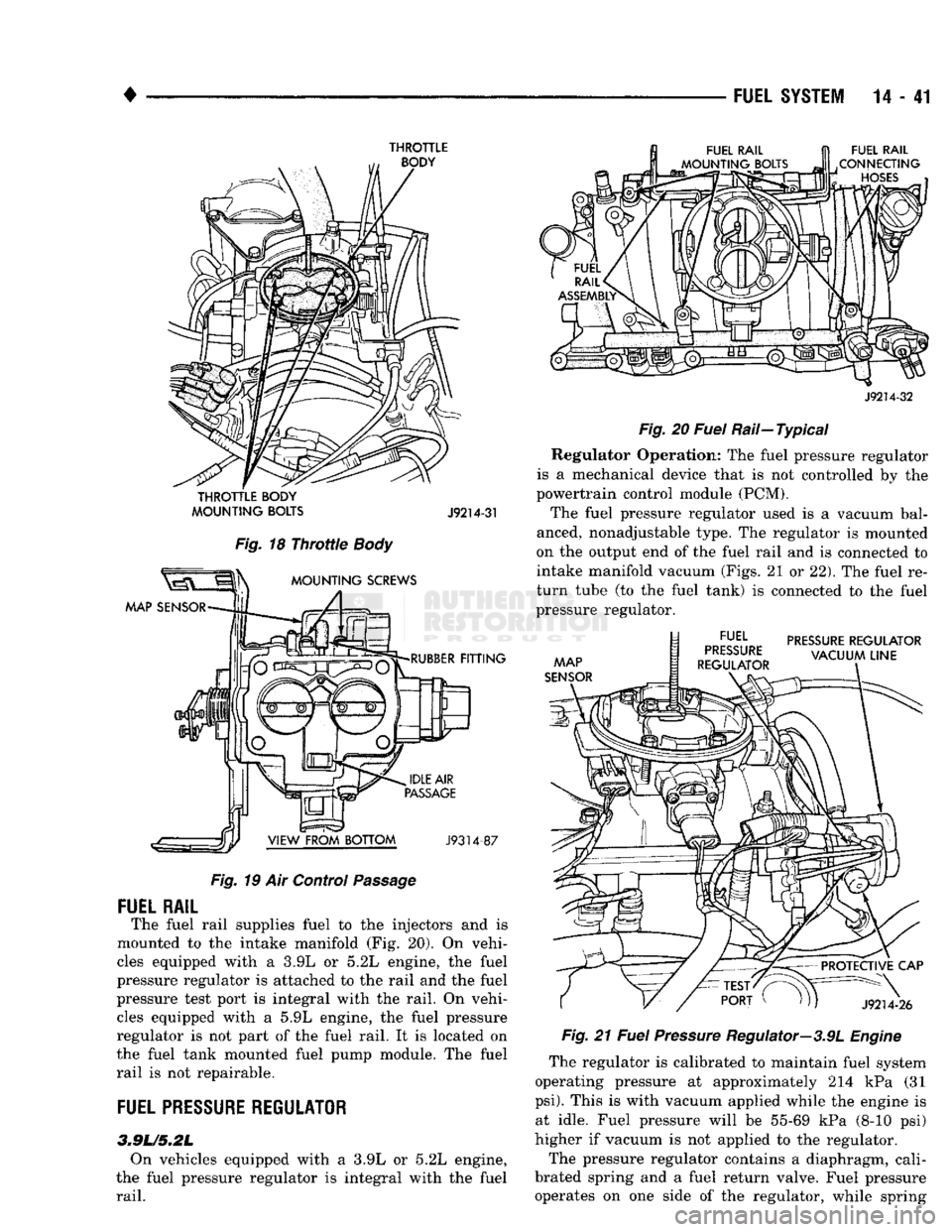
The fuel rail supplies fuel to the injectors and is
mounted to the intake manifold (Fig. 20). On vehi
cles equipped with a 3.9L or 5.2L engine, the fuel
pressure regulator is attached to the rail and the fuel
pressure test port is integral with the rail. On vehi cles equipped with a 5.9L engine, the fuel pressure
regulator is not part of the fuel rail. It is located on
the fuel tank mounted fuel pump module. The fuel
rail is not repairable.
FUEL
PRESSURE
REGULATOR
3.9L/5.2L On vehicles equipped with a 3.9L or 5.2L engine,
the fuel pressure regulator is integral with the fuel
rail.
J9214-32
Fig.
20
Fuel
Rail—Typical Regulator Operation: The fuel pressure regulator
is a mechanical device that is not controlled by the
powertrain control module (PCM).
The fuel pressure regulator used is a vacuum bal
anced, nonadjustable type. The regulator is mounted
on the output end of the fuel rail and is connected to
intake manifold vacuum (Figs. 21 or 22). The fuel re
turn tube (to the fuel tank) is connected to the fuel
pressure regulator.
MAP
SENSOR
docc EL
PRESSURE
REGULATOR
„
VACUUM
LINE
REGULATOR
PROTECTIVE
CAP
J9214-26
Fig.
21
Fuel
Pressure
Regulator—3.9L
Engine
The regulator is calibrated to maintain fuel system
operating pressure at approximately 214 kPa (31
psi).
This is with vacuum applied while the engine is at idle. Fuel pressure will be 55-69 kPa (8-10 psi)
higher if vacuum is not applied to the regulator.
The pressure regulator contains a diaphragm, cali
brated spring and a fuel return valve. Fuel pressure operates on one side of the regulator, while spring
Page 861 of 1502
VACUUM
LINE
PROTECTIVE
CAP
INTERNAL
FUEL FILTER FUEL
PRESSURE
REGULATOR FUEL RAIL
CONNECTOR
HOSES
J9214-27
Fig.
22
Fuel
Pressure
Regulator—5.2L
Engine
pressure
and
intake manifold vacuum operate
on the
other side. Spring pressure
on one
side
of the
dia
phragm tries
to
force
the
return valve closed. Fuel
pressure
on
other side
of
diaphragm, with assistance from manifold vacuum
on
spring side
of
diaphragm, act against spring pressure
to
open
the
return valve.
System fuel pressure
is the
amount
of
fuel pressure
required
to
force against spring pressure
and
unseat
the return valve.
Without vacuum applied
to the
spring side
of the
regulator,
the
spring
is
calibrated
to
open
the
fuel
re
turn outlet. This happens when
the
pressure differen
tial between
the
fuel injectors
and the
intake
manifold reaches approximately
269 kPa (39 psi).
Since manifold vacuum varies with engine operating
conditions,
the
amount
of
vacuum applied
to the
spring side
of the
diaphragm varies.
For
this reason,
fuel pressure varies, depending upon intake manifold
vacuum. With
low
vacuum, such
as
during wide open
throttle conditions, minimal vacuum assistance
is
available. Full spring pressure
is
exerted
to
seal
the
fuel outlet. This causes
the
system pressure
to in
crease. With high vacuum, such
as at
engine idle
or
during vehicle deceleration, fuel pressure
on one
side
of
the
diaphragm
is
balanced
by
intake manifold
pressure. This
is
done
on the
spring side
of the
dia
phragm
and
results
in
lower system fuel pressure.
5.9L
ENGINE
On vehicles equipped with
a 5.9L
engine,
the
fuel
filter and fuel pressure regulator
are one
combined
part
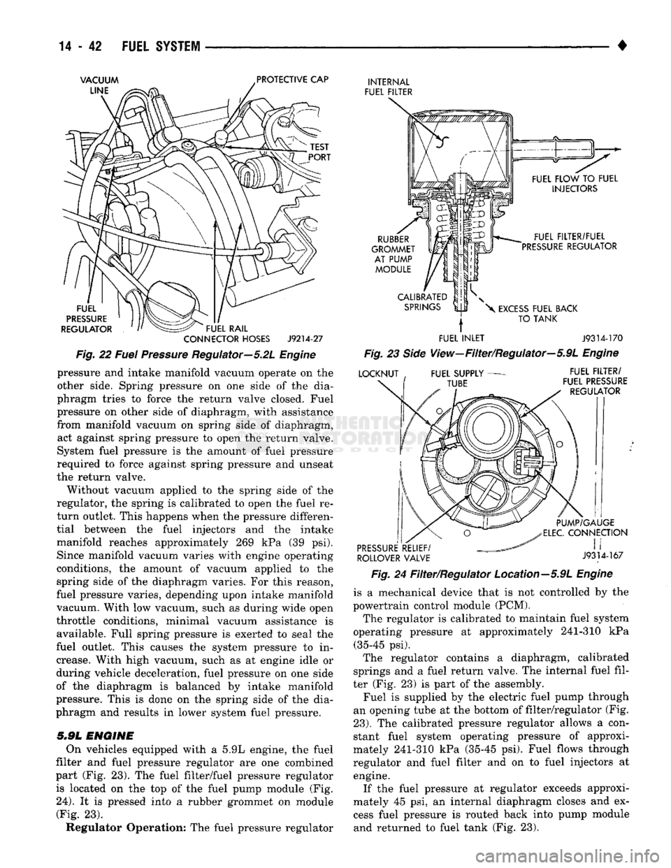
(Fig. 23). The
fuel filter/fuel pressure regulator is located
on the top of the
fuel pump module
(Fig.
24).
It is
pressed into
a
rubber grommet
on
module (Fig.
23).
Regulator Operation:
The
fuel pressure regulator
RUBBER
GROMMET AT PUMP MODULE FUEL FILTER/FUEL
PRESSURE REGULATOR
CALIBRATED SPRINGS
X
EXCESS FUEL BACK
TO TANK
FUEL INLET J9314-170
Fig.
23
Side
View—Filter/Regulator—5.9L
Engine
LOCKNUT FUEL SUPPLY
TUBE FUEL FILTER/
FUEL PRESSURE REGULATOR PUMP/GAUGE
ELEC.
CONNECTION
PRESSURE RELIEF/
, I I
ROLLOVER VALVE
J9314-167
Fig.
24
Filter/Regulator Location—5.9L
Engine
is
a
mechanical device that
is not
controlled
by the
powertrain control module (PCM).
The regulator
is
calibrated
to
maintain fuel system
operating pressure
at
approximately 241-310
kPa
(35-45
psi).
The regulator contains
a
diaphragm, calibrated
springs
and a
fuel return valve.
The
internal fuel fil
ter
(Fig. 23) is
part
of the
assembly. Fuel
is
supplied
by the
electric fuel pump through
an opening tube
at the
bottom
of
filter/regulator
(Fig.
23).
The
calibrated pressure regulator allows
a
con
stant fuel system operating pressure
of
approxi
mately 241-310
kPa
(35-45
psi).
Fuel flows through
regulator
and
fuel filter
and on to
fuel injectors
at
engine. If
the
fuel pressure
at
regulator exceeds approxi
mately
45 psi, an
internal diaphragm closes
and ex
cess fuel pressure
is
routed back into pump module and returned
to
fuel tank
(Fig. 23).
Page 863 of 1502
14 - 44
FUEL
SYSTEM
•
Fig.
4 ignition Coil—5.9L
HDC-Gas
Engine
(5) Verify that distributor cap is correctly attached
to distributor. Be sure that spark plug cables are
firmly connected to the distributor cap and the spark
plugs are in their correct firing order. Be sure that coil cable is firmly connected to distributor cap and
coil. Be sure that camshaft position sensor wire con
nector (at the distributor) is firmly connected to har
ness connector. Inspect spark plug condition. Refer to Group 8D, Ignition. Connect vehicle to an oscillo
scope and inspect spark events for fouled or damaged
spark plugs or cables.
(6) Verify that generator output wire, generator
connector and ground wire are firmly connected to
the generator. (7) Inspect the system body grounds for loose or
dirty connections. Refer to Group 8, Wiring for
ground locations. (8) Verify positive crankcase ventilation (PCV)
valve operation. Refer to Group 25, Emission Control System for additional information. Verify PCV valve
hose is firmly connected to PCV valve and manifold (Fig. 5).
Fig.
5 PCV
Valve
Hose
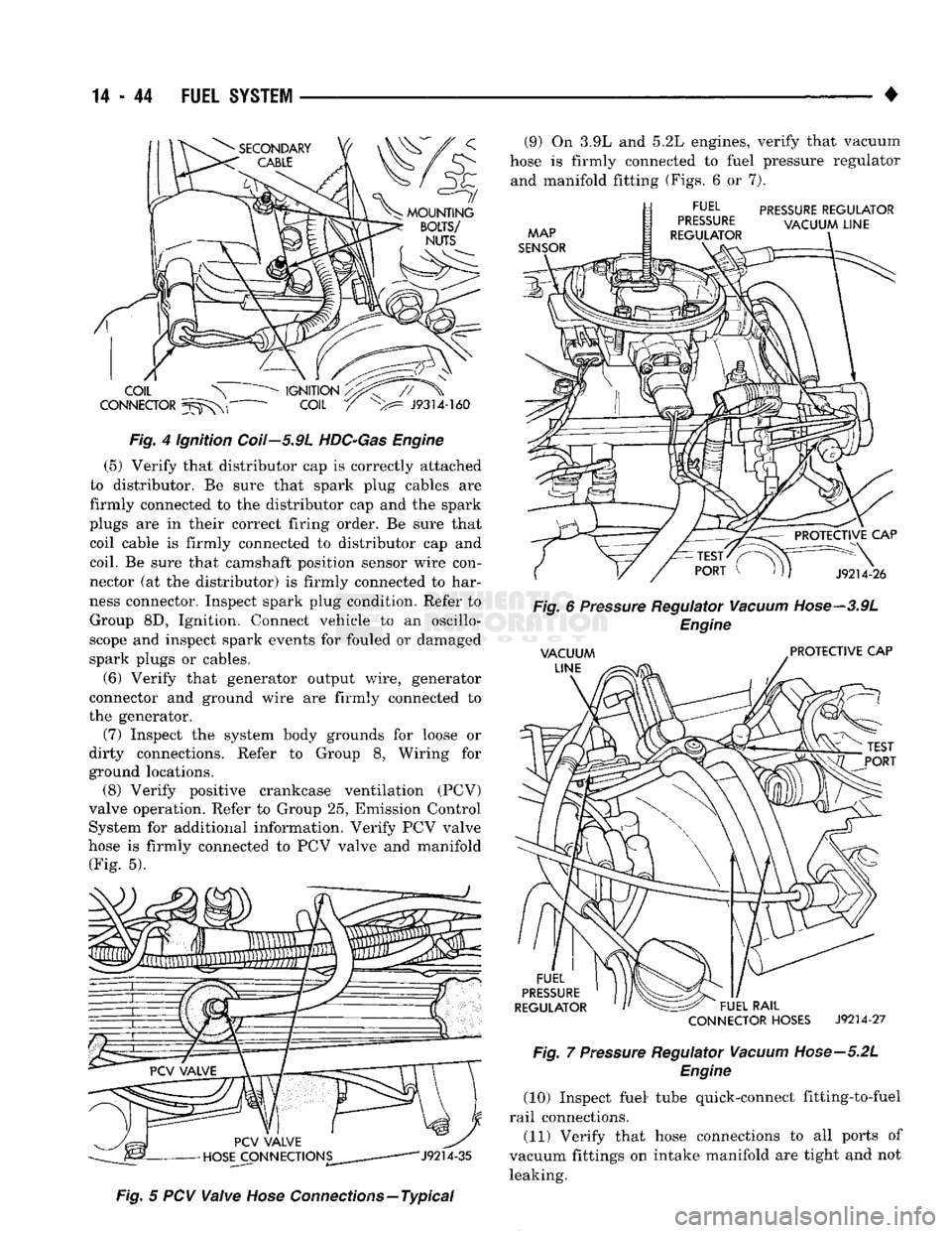
Connections—Typical (9) On 3.9L and 5.2L engines, verify that vacuum
hose is firmly connected to fuel pressure regulator and manifold fitting (Figs. 6 or 7).
CONNECTOR
HOSES
J9214-27
Fig.
7
Pressure
Regulator
Vacuum
Hose—5.2L
Engine
(10) Inspect fuel* tube quick-connect fitting-to-fuel
rail connections. (11) Verify that hose connections to all ports of
vacuum fittings on intake manifold are tight and not leaking.
Page 877 of 1502
14 - 58
FUEL
SYSTEM
• INJECTOR DIAGNOSIS-VEHICLE RUNS ROUGH AND/OR HAS A
MISS
DO PRELIMINARY INSPECTION OF DISTRIBUTOR CAP,
IGNITION
CABLES
SPARK
PLUGS,
AND
CHECK
FOR VACUUM
LEAKS.
START VEHICLE, PULL THE
ELECTRICAL
CONNECTORS OFF
THE INJECTORS ONE AT A TIME
TO DETERMINE
WHICH
CYLINDER
IS
NOT FIRING.
REPLACE
THE INJECTOR -NO •
CHECK
POWER FEED AND
GROUND CIRCUITS BETWEEN POWERTRAIN CONTROL MODULE
AND THE INJECTOR CONNECTOR.
REFER
TO WIRING SCHEMATIC
FOR COLOR CODES AND PIN
TERMINAL NUMBERS. - NO-
YES
TEST THE VEHICLE
WITH
THE DRB II
SCAN
TOOL
NO
REPAIR
OR REPLACE THE WIRING
HARNESS
AS NECESSARY.
REPLACE
INJECTOR IF VISUALLY
PLUGGED
AT INJECTOR FUEL INLET.
REPLACE
FUEL RAIL IF VISUALLY
PLUGGED
OR RESTRICTED AT INJECTOR DELIVERY COUPLING. -NO
REPLACE
INJECTOR •NO-TEST THE INJECTOR RESISTANCE
USING AN OHMMETER
ACROSS
THE INJECTOR TERMINALS
WITH
THE INJECTOR CONNECTOR
REMOVED.
PLACE
A 12
VOLT
TEST LAMP
ACROSS
THE INJECTOR
ELECTRICAL
CONNECTOR
TERMINALS.
OBSERVE THE TEST LAMP WHILE CRANKING THE
ENGINE.
CIRCUIT IS OK. CHECK FOR FUEL DELIVERY AT SUSPECT INJECTOR
BY
REMOVING THE INJECTOR FROM THE RAIL AND OBSERVING
FOR FUEL AND/OR RESTRICTIONS IN THE RAIL OR INJECTOR FUEL INLET.
WITH
INJECTOR REMOVED FROM
THE FUEL RAIL, CONNECT A 12V
SOURCE
TO ONE TERMINAL ON
THE INJECTOR CONNECTOR AND
A
GROUND WIRE TO THE OTHER
TERMINAL. THE INJECTOR SHOULD "CLICK" EACH TIME THE GROUND WIRE IS CONNECTED
AND DISCONNECTED TO THE TERMINAL.
J9314-114
Page 883 of 1502
MULTI-PORT
FUEL
INJECTION
(MPI)-COMPONENT
REMOVAL/INSTALLATION
—EXCEPT DIESEL
INDEX
page
Accelerator Pedal
and Throttle
Cable
. 64
Air Conditioning (A/C) Clutch Relay
64
Air
Filter/Filter
Housing
64
Automatic Shut Down (ASD) Relay
. 64
Brake
Switch
64
Camshaft
Position
Sensor
..................
64
Charge
Air
Temperature
Sensor
64
Crankshaft Position
Sensor
64
Engine
Coolant Temperature
Sensor
65
EVAP
Canister Purge Solenoid
65
Fuel
Filter
65
Fuel Filter/Fuel Pressure Regulator—5.9L Engine
. 65
Fuel Injector(S)
67
Fuel Pressure Regulator
67
Fuel Pump Module
68
Fuel Pump Relay
68
ACCELERATOR
PEDAL
AND THROTTLE
CABLE
Refer
to
the
Accelerator Pedal
and
Throttle Cable
section
of
this group
for
removal/installation proce
dures.
AIR
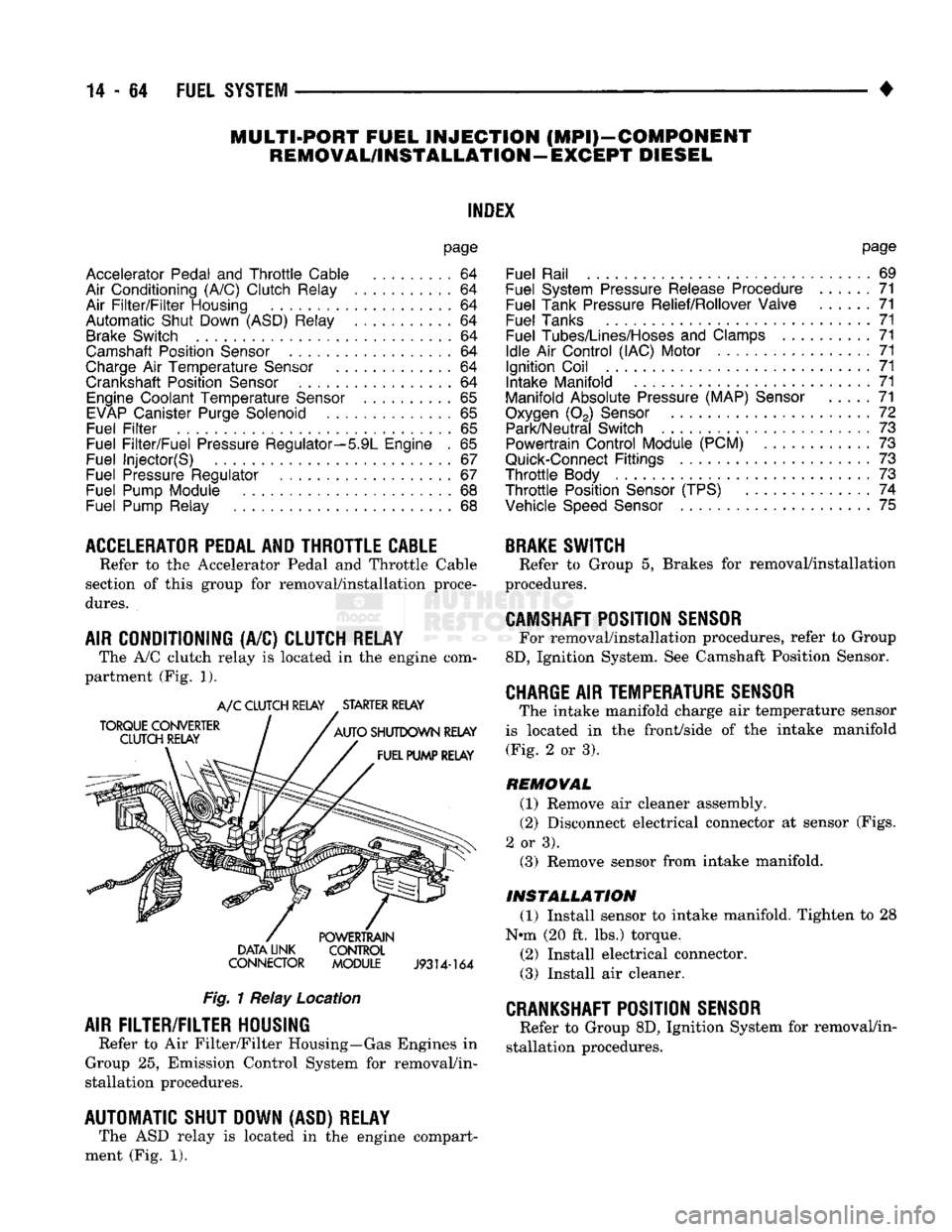
CONDITIONING (A/C) CLUTCH RELAY The A/C clutch relay
is
located
in
the
engine com
partment (Fig.
1).
A/C CLUTCH RELAY STARTER RELAY
DATA LINK CONTROL
CONNECTOR MODULE
J9314-164
Fig.
1 Relay Location
AIR
FILTER/FILTER
HOUSING
Refer
to
Air Filter/Filter Housing—Gas Engines
in
Group
25,
Emission Control System
for
removal/in
stallation procedures.
AUTOMATIC SHUT DOWN (ASD) RELAY The ASD relay
is
located
in
the
engine compart
ment (Fig.
1).
page
Fuel Rail
69
Fuel System Pressure Release Procedure
......
71
Fuel Tank Pressure Relief/Rollover Valve
71
Fuel Tanks
71
Fuel
Tubes/Lines/Hoses
and
Clamps
71
Idle
Air
Control (IAC) Motor
71
Ignition Coil
71
Intake Manifold
71
Manifold Absolute Pressure (MAP)
Sensor
71
Oxygen
(02)
Sensor
72
Park/Neutral Switch
. 73
Powertrain Control Module (PCM)
73
Quick-Connect
Fittings
73
Throttle
Body
73
Throttle
Position
Sensor
(TPS)
......
74
Vehicle
Speed
Sensor
75
BRAKE
SWITCH
Refer
to
Group
5,
Brakes
for
removal/installation
procedures.
CAMSHAFT
POSITION
SENSOR
For removal/installation procedures, refer
to
Group
8D,
Ignition System. See Camshaft Position Sensor.
CHARGE
AIR
TEMPERATURE SENSOR
The intake manifold charge
air
temperature sensor
is located
in the
front/side
of
the
intake manifold (Fig.
2
or
3).
REMOVAL
(1) Remove
air
cleaner assembly.
(2) Disconnect electrical connector
at
sensor (Figs.
2
or
3). (3) Remove sensor from intake manifold.
INSTALLATION
(1) Install sensor
to
intake manifold. Tighten
to 28
Nnn (20
ft.
lbs.) torque.
(2) Install electrical connector.
(3) Install
air
cleaner.
CRANKSHAFT
POSITION
SENSOR
Refer
to
Group 8D, Ignition System
for
removal/in
stallation procedures.
Page 884 of 1502
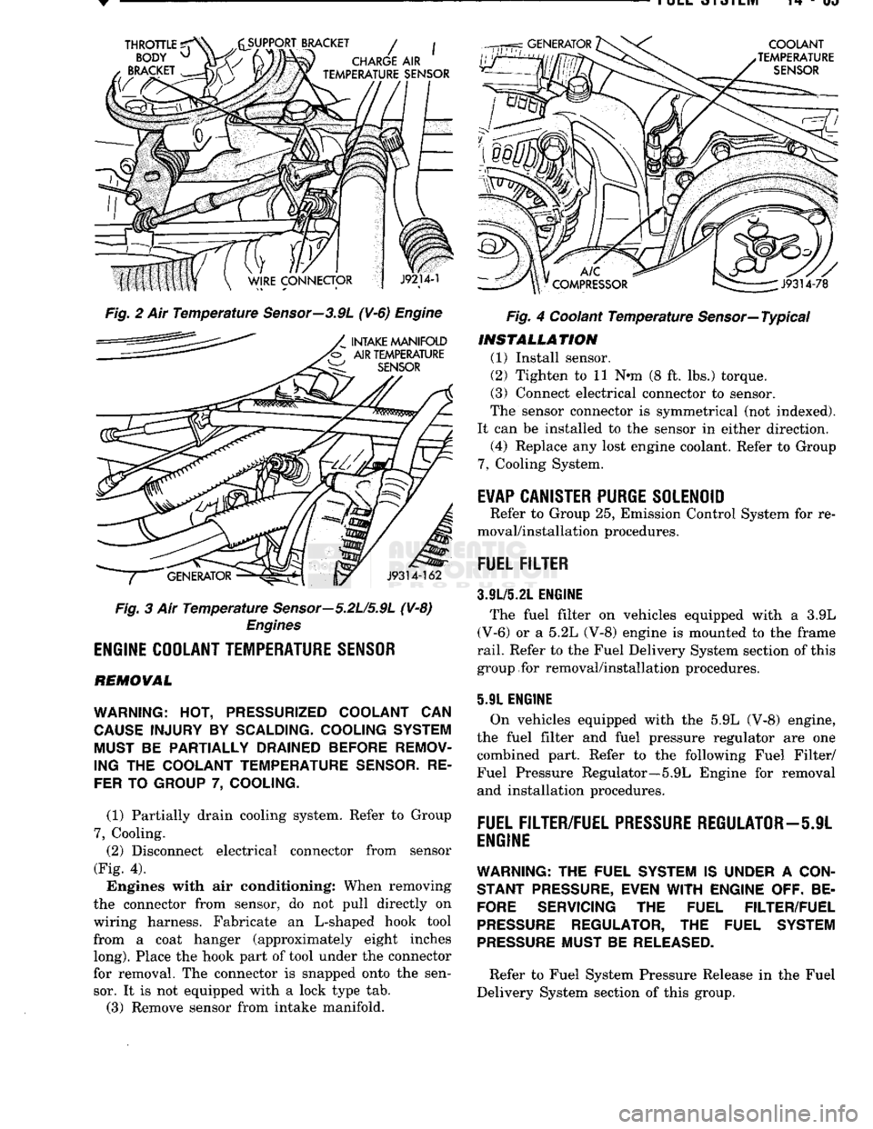
Fig. 2 Ait Temperature Sensor—3.9L (¥-6) Engine
Fig. 3 Air Temperature Sensor—5.2U5.9L (V-8)
Engines
ENGINE
COOLANT
TEMPERATURE
SENSOR
REMOVAL
WARNING:
HOT,
PRESSURIZED COOLANT
CAN
CAUSE
INJURY
BY
SCALDING- COOLING SYSTEM MUST
BE
PARTIALLY DRAINED BEFORE REMOV
ING
THE
COOLANT TEMPERATURE
SENSOR.
RE
FER
TO
GROUP
7,
COOLING.
(1) Partially drain cooling system. Refer to Group
7,
Cooling. (2) Disconnect electrical connector from sensor
(Fig. 4).
Engines with air conditioning: When removing
the connector from sensor, do not pull directly on
wiring harness. Fabricate an L-shaped hook tool from a coat hanger (approximately eight inches
long).
Place the hook part of tool under the connector
for removal. The connector is snapped onto the sen sor. It is not equipped with a lock type tab.
(3) Remove sensor from intake manifold. Fig. 4 Coolant Temperature Sensor—Typical
INSTALLATION
(1) Install sensor.
(2) Tighten to 11 Nnn (8 ft. lbs.) torque.
(3) Connect electrical connector to sensor.
The sensor connector is symmetrical (not indexed).
It can be installed to the sensor in either direction. (4) Replace any lost engine coolant. Refer to Group
7,
Cooling System.
E¥AP
CANISTER
PURGE
SOLENOID
Refer to Group 25, Emission Control System for re
moval/installation procedures.
FUEL
FILTER
3.9L/5.21.
ENGINE
The fuel filter on vehicles equipped with a 3.9L
(V-6) or a 5.2L (V-8) engine is mounted to the frame
rail.
Refer to the Fuel Delivery System section of this
group for removal/installation procedures.
5.91 ENGINE
On vehicles equipped with the 5.9L (V-8) engine,
the fuel filter and fuel pressure regulator are one combined part. Refer to the following Fuel Filter/
Fuel Pressure Regulator—5.9L Engine for removal and installation procedures.
FUEL
FILTER/FUEL
PRESSURE
REGULATOR—5JL
ENGINE
WARNING:
THE FUEL SYSTEM IS UNDER A
CON
STANT
PRESSURE,
EVEN
WITH
ENGINE OFF. BE
FORE
SERVICING THE FUEL FILTER/FUEL
PRESSURE
REGULATOR, THE FUEL SYSTEM
PRESSURE
MUST BE
RELEASED.
Refer to Fuel System Pressure Release in the Fuel
Delivery System section of this group.
Page 886 of 1502
•
FUEL SYSTEM 14-67
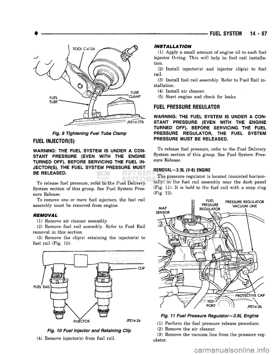
Fig. 9 Tightening Fuel Tube Clamp
FUEL INJECTOR(S)
WARNING;
THE
FUEL
SYSTEM IS
UNDER
A
CON
STANT PRESSURE (EVEN
WITH THE
ENGINE
TURNED
OFF).
BEFORE SERVICING
THE
FUEL
IN
JECTOR^),
THE
FUEL
SYSTEM
PRESSURE MUST
BE
RELEASED.
To release fuel pressure, refer to the Fuel Delivery
System section of this group. See Fuel System Pres sure Release.
To remove one or more fuel injectors, the fuel rail
assembly must be removed from engine.
REMOVAL
(1) Remove air cleaner assembly. (2) Remove fuel rail assembly. Refer to Fuel Rail
removal in this section.
(3) Remove the clip(s) retaining the injector(s) to
fuel rail (Fig. 10).
CUP
Fig. 10 Fuel Injector and Retaining Clip
(4) Remove injector(s) from fuel rail.
INSTALLATION
(1) Apply a small amount of engine oil to each fuel
injector O-ring. This will help in fuel rail installa
tion.
(2) Install injector(s) and injector clip(s) to fuel
rail.
(3) Install fuel rail assembly. Refer to Fuel Rail in
stallation.
(4) Install air cleaner.
(5) Start engine and check for leaks.
FUEL PRESSURE REGULATOR
WARNING:
THE
FUEL SYSTEM
IS
UNDER
A
CON STANT PRESSURE (EVEN
WITH
THE
ENGINE
TURNED
OFF).
BEFORE SERVICING
THE
FUEL
PRESSURE
REGULATOR,
THE
FUEL SYSTEM
PRESSURE
MUST
BE
RELEASED.
To release fuel pressure, refer to the Fuel Delivery
System section of this group. See Fuel System Pres
sure Release.
REMOVAL—3JL
(V-6)
ENGINE
The pressure regulator is located (mounted horizon
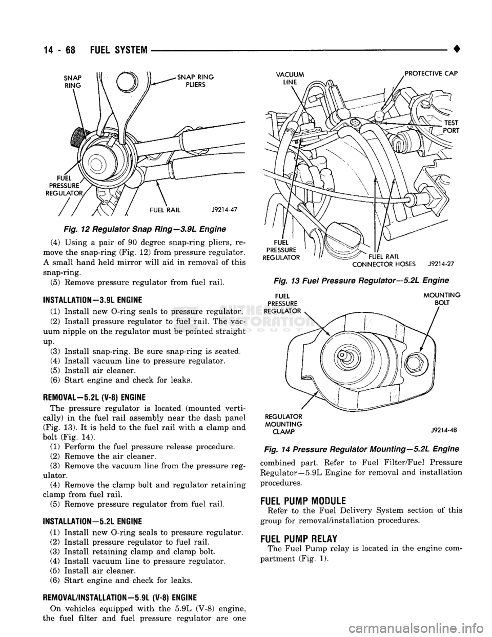
tally) in the fuel rail assembly near the dash panel (Fig. 11). It is held to the fuel rail with a snap ring
(Fig. 12). Fig. 11 Fuel Pressure Regulator—3.9L Engine
(1) Perform the fuel pressure release procedure.
(2) Remove the air cleaner.
(3)
Remove the vacuum line from the pressure reg
ulator.
Page 887 of 1502
14
- 68
FUEL
SYSTEM
•
SNAP
RING
SNAP
RING
PLIERS
VACUUM
LINE
PROTECTIVE CAP
FUEL
PRESSURE
REGULATOR,
FUEL RAIL
J9214-47
Fig. 12 Regulator Snap Ring—3.9L Engine (4) Using a pair of 90 degree snap-ring pliers, re
move the snap-ring (Fig. 12) from pressure regulator.
A small hand held mirror will aid in removal of this snap-ring.
(5) Remove pressure regulator from fuel rail.
INSTALLATION—3.9L
ENGINE
(1) Install new O-ring seals to pressure regulator.
(2) Install pressure regulator to fuel rail. The vac
uum nipple on the regulator must be pointed straight
up.
(3) Install snap-ring. Be sure snap-ring is seated.
(4) Install vacuum line to pressure regulator.
(5) Install air cleaner.
(6) Start engine and check for leaks.
REMOVAL-5.21
(¥-8) ENGINE The pressure regulator is located (mounted verti
cally) in the fuel rail assembly near the dash panel (Fig. 13). It is Jield to the fuel rail with a clamp and
bolt (Fig. 14).
(1) Perform the fuel pressure release procedure.
(2) Remove the air cleaner.
(3) Remove the vacuum line from the pressure reg
ulator. (4) Remove the clamp bolt and regulator retaining
clamp from fuel rail.
(5) Remove pressure regulator from fuel rail.
INSTALLATION—5.2L
ENGINE
(1) Install new O-ring seals to pressure regulator.
(2) Install pressure regulator to fuel rail. (3) Install retaining clamp and clamp bolt.
(4) Install vacuum line to pressure regulator.
(5) Install air cleaner.
(6) Start engine and check for leaks.
REMOVAL/INSTALLATION—iJL (V-8) ENGINE
On vehicles equipped with the 5.9L (V-8) engine,
the fuel filter and fuel pressure regulator are one
FUEL
PRESSURE
REGULATOR FUEL RAIL
CONNECTOR
HOSES
J9214-27
Fig. 13 Fuel Pressure Regulator—5.2L Engine
FUEL
PRESSURE
REGULATOR MOUNTING
BOLT REGULATOR
MOUNTING CLAMP
J9214-48
Fig. 14 Pressure Regulator Mounting—5.2L Engine combined part. Refer to Fuel Filter/Fuel Pressure
Regulator—5.9L Engine for removal and installation
procedures.
FUEL
PUMP
MODULE
Refer to the Fuel Delivery System section of this
group for removal/installation procedures.
FUEL
PUMP
RELAY
The Fuel Pump relay is located in the engine com
partment (Fig. 1).