1993 DODGE TRUCK overdrive switch
[x] Cancel search: overdrive switchPage 848 of 1502
•
FUEL
SYSTEM
14-29
MULTI-PORT
FUEL
INJECTION
(MPI)-COMPONENT DESCRIPTION/SYSTEM
OPERATION-EXCEPT DIESEL
INDEX
page
Air
Conditioning (A/C) Clutch
Relay-Pern
Output
. 35
Air
Conditioning (A/C)
Controls—PCM
Input
.... 31
Auto
Shut
Down
(ASD)
Relay-PCM
Output
. ... 36
Automatic
Shut
Down
(ASD)
Sense-PCM
Input
. 31
Battery
Voltage-PCM
Input
32
Brake
Switch-PCM
Input
32
Camshaft
Position
Sensor—PCM
Input
32
Charge
Air
Temperature
Sensor—PCM
Input
. . . 32
Crankshaft
Position
Sensor-PCM
Input
.......
32
Electric
Exhaust
Gas Recirculation Transducer
(EET)
Solenoid-PCM
Output
...
.......
36
Engine
Coolant Temperature
Sensor—PCM
Input
. 33
EVAP
Canister
Purge
Solenoid—PCM
Output
. . . 37
Fuel
Injectors-PCM Output
37
Fuel
Pressure
Regulator
41
Fuel
Rail
41
General
Information
.......................
29
Generator
Field-PCM
Output
36
Generator
Lamp-PCM
Output
36
Idle
Air
Control
(IAC)
Motor-PCM
Output
......
36
Ignition
Circuit
Sense—PCM
Input
33
GENERAL
INFORMATION
All
gas
powered engines
are
equipped with sequen
tial Multi-Port Fuel Injection (MPI).
The MPI
system (Fig.
1)
provides precise air/fuel ratios
for all
driving
conditions. The Powertrain Control Module
(PCM)
operates
the fuel system.
The PCM was
formerly referred
to
as
the
SBEC
or
engine controller.
The PCM is a
pre
programmed, dual microprocessor digital computer. It regulates ignition timing, air-fuel ratio, emission
control devices, charging system, speed control,
air
conditioning compressor clutch engagement
and
idle speed.
The PCM can
adapt
its
programming
to
meet
changing operating conditions.
Powertrain Control Module (PCM) Inputs rep
resent
the
instantaneous engine operating conditions.
Air-fuel mixture
and
ignition timing calibrations
for
various driving
and
atmospheric conditions
are
pre
programmed into
the PCM. The PCM
monitors
and
analyzes various inputs.
It
then computes engine fuel
and ignition timing requirements based
on
these
in
puts.
Fuel delivery control
and
ignition timing will
then
be
adjusted accordingly. Other inputs
to the
PCM
are
provided
by the
brake
light switch,
air
conditioning select switch
and the
speed control switches.
All
inputs
to the PCM are
converted into signals. Electrically operated fuel injectors spray fuel
in
precise metered amounts into
the
intake port directly above
the
intake valve.
The
injectors
are
fired
in a
specific sequence
by the PCM. The PCM
maintains
page
Ignition
Coil-PCM
Output
37
Malfunction Indicator
Lamp—PCM
Output
37
Manifold
Absolute
Pressure
(MAP)
Sensor-
PCM
Input
33
Open
Loop/Closed
Loop
Modes
of
Operation
. . . 38
Overdrive/Override
Switch
34
Oxygen
(02)
Sensor—PCM
Input
33
Park/Neutral
Switch—PCM
Input
34
Power
Ground
34
Powertrain Control Module
(PCM)
30
SCI
Receive-PCM
Input
. 34
SCI
Transmit-PCM
Output
37
Sensor
Return
—PCM
Input
35
Shift Indicator-PCM Output
38
Speed
Control-PCM
Input
34
Speed
Control-PCM
Output
38
SRI
Lamp-PCM
Output
36
Tachometer—PCM
Output
38
Throttle
Body
40
Throttle
Position
Sensor
(TPS)-PCM
Input
35
Vehicle
Speed
Sensor-PCM
Input
35
an air/fuel ratio
of 14.7 to 1 by
constantly adjusting
injector pulse width. Injector pulse width
is the
length
of
time that
the
injector opens
and
sprays fuel into
the
chamber.
The PCM
adjusts injector pulse
width
by
opening
and
closing
the
ground path
to the
injector.
Manifold absolute pressure
(air
density)
and
engine
rpm (speed)
are the
primary inputs that determine
fuel injector pulse width.
The PCM
also monitors
other inputs when adjusting air-fuel ratio.
Inputs That Effect Fuel Injector Pulse Width:
• Exhaust
gas
oxygen content
• Coolant temperature
• Manifold absolute pressure (MAP)
• Engine speed
• Throttle position
• Battery voltage •
Air
conditioning selection
• Transmission gear selection (auto, trans.)
• Speed control The powertrain control module (PCM) adjusts igni
tion timing
by
controlling ignition coil operation.
The
ignition coil receives battery voltage when
the
igni
tion
key is in the run or
starter (crank) position.
The
PCM provides
a
ground
for the
ignition coil.
The
coil
discharges when
the PCM
supplies
a
ground.
By
switching
the
ground path
on and off, the PCM
reg
ulates ignition timing.
The sensors
and
switches that provide inputs
to the
powertrain control module
(PCM)
comprise
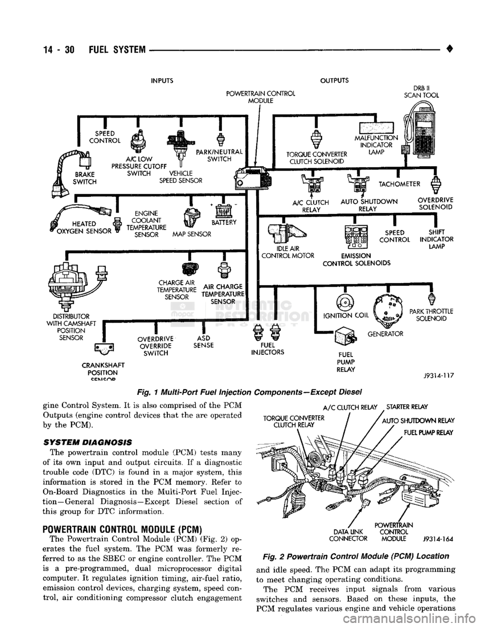
the En-
Page 849 of 1502
14
- 30
FUEL
SYSTEM
INPUTS
OUTPUTS
POWERTRAIN
CONTROL
MODULE
DRB
II
SCAN
TOOL
SPEED
CONTROL
BRAKE
SWITCH
A/C
LOW
PRESSURE
CUTOFF
SWITCH VEHICLE
SPEED
SENSOR PARK/NEUTRAL
SWITCH TORQUE CONVERTER
CLUTCH SOLENOID
MALFUNCTION
INDICATOR
LAMP
m
HEATED
i
*OXYGEN SENSOR ENGINE
COOLANT
yy
BATTERY
TEMPERATURE
SENSOR
MAP SENSOR
i—r
CHARGE
AIR
TEMPERATURE
SENSOR
AIR CHARGE
TEMPERATURE
SENSOR
DISTRIBUTOR
WITH
CAMSHAFT
r
POSITION
SENSOR
(|
TACHOMETER
A/C
CLUTCH RELAY
AUTO
SHUTDOWN
RELAY OVERDRIVE
SOLENOID
IDLE AIR
CONTROL MOTOR
SPEED
CONTROL
SHIFT
INDICATOR
LAMP
EMISSION
CONTROL SOLENOIDS
IGNITION
COIL
OVERDRIVE
OVERRIDE SWITCH
ASD
SENSE
FUEL
INJECTORS
PARK
THROTTLE
SOLENOID
GENERATOR CRANKSHAFT
POSITION FUEL
PUMP
RELAY
J9314-117
Fig.
1 Multi-Port
Fuel
Injection
Components—Except
Diesel
gine Control System. It is also comprised of the PCM Outputs (engine control devices that the are operated
by the PCM).
SYSTEM DIAGNOSIS
The powertrain control module (PCM) tests many
of its own input and output circuits. If a diagnostic
trouble code (DTC) is found in a major system, this information is stored in the PCM memory. Refer to
On-Board Diagnostics in the Multi-Port Fuel Injec
tion—General Diagnosis—Except Diesel section of
this group for DTC information.
POWERTRAIN
CONTROL MODULE (PCM)
The Powertrain Control Module (PCM) (Fig. 2) op
erates the fuel system. The PCM was formerly re
ferred to as the SBEC or engine controller. The PCM is a pre-programmed, dual microprocessor digital computer. It regulates ignition timing, air-fuel ratio, emission control devices, charging system, speed control, air conditioning compressor clutch engagement
A/C
CLUTCH RELAY STARTER RELAY
TORQUE CONVERTER CLUTCH RELAY
AUTO
SHUTDOWN RELAY
FUEL PUMP RELAY
DATA UNK
CONNECTOR
POWERTRAIN
CONTROL MODULE
J9314-164
Fig.
2 Powertrain Control
Module
(PCM) Location and idle speed. The PCM can adapt its programming
to meet changing operating conditions.
The PCM receives input signals from various
switches and sensors. Based on these inputs, the
PCM regulates various engine and vehicle operations
Page 850 of 1502
•
FUEL SYSTEM
14-31 through different system components. These compo
nents are referred to as Powertrain Control Module
(PCM) Outputs. The sensors and switches that pro
vide inputs to the PCM are considered Powertrain Control Module (PCM) Inputs.
The PCM adjusts ignition timing based upon in
puts it receives from sensors that react to: engine rpm, manifold absolute pressure, engine coolant tem
perature, throttle position, transmission gear selec
tion (automatic transmission), vehicle speed and the
brake switch.
The PCM adjusts idle speed based on inputs it re
ceives from sensors that react to: throttle position,
vehicle speed, transmission gear selection, engine coolant temperature and from inputs it receives from
the air conditioning clutch switch and brake switch.
Based on inputs that it receives, the PCM adjusts
ignition coil dwell. The PCM also adjusts the gener
ator charge rate through control of the generator
field and provides speed control operation.
Powertrain Control Module (PCM) Inputs:
• Generator output • A/C request (if equipped with factory A/C)
• A/C select (if equipped with factory A/C)
• Auto shut down (ASD) sense
• Charge air temperature sensor
• Battery voltage
• Brake switch
• Engine coolant temperature sensor
• Crankshaft position sensor • Ignition circuit sense (ignition switch in run posi
tion)
• Manifold absolute pressure (MAP) sensor
• Overdrive/override switch
• Oxygen sensor(s)
• Park/neutral switch (auto, trans, only)
• SCI receive (DRB II connection) • Speed control resume switch
• Speed control set switch • Speed control on/off switch
• Camshaft position sensor signal
• Throttle position sensor
• Vehicle speed sensor
• Sensor return
• Power ground
• Signal ground Powertrain Control Module (PCM) Outputs:
• A/C clutch relay
• Idle air control (IAC) motor
• Auto shut down (ASD) relay
• Generator field
• Malfunction indicator lamp
• Service reminder indicator lamp
• EGR valve control solenoid • Fuel injectors
• Fuel pump relay
• Ignition coil • EVAP canister purge solenoid
• SCI transmit (DRB II connection)
• Shift indicator lamp (manual transmission only)
• Speed control vacuum solenoid
• Speed control vent solenoid
• Tachometer (on instrument panel, if equipped) The powertrain control module (PCM) contains a
voltage convertor. This converts battery voltage to a
regulated 8.0 volts. It is used to power the crankshaft
position sensor and camshaft position sensor. The
PCM also provides a five (5) volt supply for the man ifold absolute pressure (MAP) sensor and throttle po
sition sensor (TPS).
AIR
CONDITIONING
(A/C)
CONTROLS-PCM
INPUT
The A/C control system information applies to fac
tory installed air conditioning units. A/C SELECT SIGNAL: When the A/C switch is
in the ON position and the A/C low pressure switch
is closed, an input signal is sent to the powertrain
control module (PCM). The signal informs the PCM
that the A/C has been selected. The PCM adjusts idle speed to a pre-programmed rpm through the idle air
control (IAC) motor to compensate for increased en
gine load. A/C REQUEST SIGNAL: Once A/C has been se
lected, the powertrain control module (PCM) receives
the A/C request signal from the evaporator switch.
The input indicates that the evaporator temperature is in the proper range for A/C application. The PCM
uses this input to cycle the A/C compressor clutch (through the A/C relay). It will also determine the
correct engine idle speed through the idle air control (IAC) motor position. If the A/C low pressure switch opens (indicating a
low refrigerant level), the PCM will not receive an
A/C select signal. The PCM will then remove the ground from the A/C relay. This will deactivate the
A/C compressor clutch. If the evaporator switch opens, (indicating that
evaporator is not in proper temperature range), the
PCM will not receive the A/C request signal. The
PCM will then remove the ground from the A/C re lay, deactivating the A/C compressor clutch.
AUTOMATIC SHUT DOWN
(ASD)
SENSE-PCM INPUT
A 12 volt signal at this input indicates to the PCM
that the ASD has been activated. The ASD relay is located in the engine compartment (Fig. 2). It is used
to connect the oxygen sensor(s) heater element, igni
tion coil, generator field winding and fuel injectors to 12 volt + power supply. This input is used only to sense that the ASD relay
is energized. If the powertrain control module (PCM)
does not see 12 volts at this input when the ASD
should be activated, it will set a diagnostic trouble
code (DTC).
Page 853 of 1502
14
- 34
FUEL SYSTEM
width accordingly. During Open Loop operation, the
PCM ignores the 02 sensor input and adjusts injector
pulse width to a preprogrammed value (based on other sensor inputs).
EXHAUST
PIPE J9214-5
Fig. 8 Oxygen Sensor Location—3.9L/5.2L/5.9L LDC Engine
5,9L HDC
ENGINE
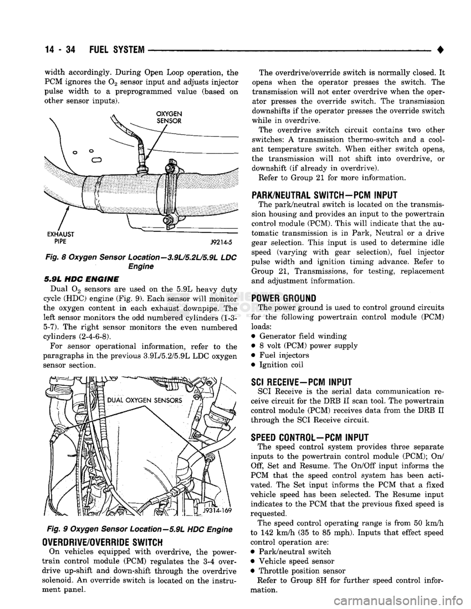
Dual 02 sensors are used on the 5.9L heavy duty
cycle (HDC) engine (Fig. 9). Each sensor will monitor
the oxygen content in each exhaust downpipe. The left sensor monitors the odd numbered cylinders (1-3-5-7). The right sensor monitors the even numbered
cylinders (2-4-6-8),
For sensor operational information, refer to the
paragraphs in the previous 3.9L/5.2/5.9L LDC oxygen sensor section. Fig. 9 Oxygen Sensor Location—5.9L HDC Engine
OVERDRIVE/OWERRIDE
SWITCH
On vehicles equipped with overdrive, the power-
train control module (PCM) regulates the 3-4 over drive up-shift and down-shift through the overdrive solenoid. An override switch is located on the instru
ment panel. The overdrive/override switch is normally closed. It
opens when the operator presses the switch. The
transmission will not enter overdrive when the oper ator presses the override switch. The transmission
downshifts if the operator presses the override switch
while in overdrive.
The overdrive switch circuit contains two other
switches: A transmission thermo-switch and a cool
ant temperature switch. When either switch opens,
the transmission will not shift into overdrive, or downshift (if already in overdrive).
Refer to Group 21 for more information.
PARK/NEUTRAL SWITCH-PCM
INPUT
The park/neutral switch is located on the transmis
sion housing and provides an input to the powertrain
control module (PCM). This will indicate that the au
tomatic transmission is in Park, Neutral or a drive
gear selection. This input is used to determine idle
speed (varying with gear selection), fuel injector
pulse width and ignition timing advance. Refer to Group 21, Transmissions, for testing, replacement
and adjustment information.
POWER
GROUND
The power ground is used to control ground circuits
for the following powertrain control module (PCM)
loads:
• Generator field winding
• 8 volt (PCM) power supply
• Fuel injectors
• Ignition coil
SCI
RECEIVE-PCM
INPUT
SCI Receive is the serial data communication re
ceive circuit for the DRB II scan tool. The powertrain
control module (PCM) receives data from the DRB II
through the SCI Receive circuit.
SPEED
CONTROL-PCM INPUT
The speed control system provides three separate
inputs to the powertrain control module (PCM); On/ Off, Set and Resume. The On/Off input informs the
PCM that the speed control system has been acti
vated. The Set input informs the PCM that a fixed
vehicle speed has been selected. The Resume input indicates to the PCM that the previous fixed speed is
requested. The speed control operating range is from 50 km/h
to 142 km/h (35 to 85 mph). Inputs that effect speed control operation are:
• Park/neutral switch
• Vehicle speed sensor
• Throttle position sensor Refer to Group 8H for further speed control infor
mation.
Page 867 of 1502
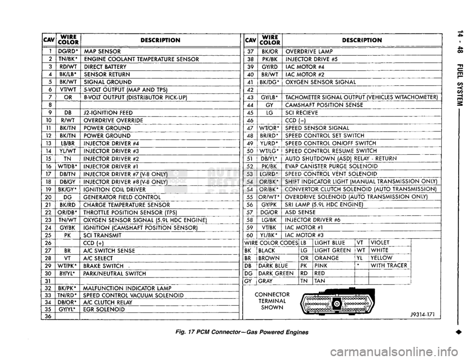
CAV
WIRE
COLOR DESCRIPTION
CAV
WIRE
COLOR DESCRIPTION
1 DG/RD*
MAP SENSOR 37
BK/OR OVERDRIVE LAMP
2 TN/BK*
ENGINE COOLANT TEMPERATURE SENSOR 38 PK/BK INJECTOR DRIVE
#5
3 RD/WT DIRECT BATTERY 39 GY/RD IAC MOTOR
#4
4
BK/LB*
SENSOR RETURN 40 BR/WT
IAC MOTOR
#2
5 BK/WT SIGNAL GROUND 41
BK/DG* OXYGEN SENSOR SIGNAL
6 VT/WT
5-VOLT
OUTPUT
(MAP AND TPS)
42
7 OR
8-VOLT
OUTPUT (DISTRIBUTOR PICK-UP) 43
GY/LB*
TACHOMETER SIGNAL OUTPUT (VEHICLES W/TACHOMETER)
8 44 GY CAMSHAFT POSITION SENSE
9 DB
J2-IGNITION FEED 45
LG SCI RECIEVE
10 R/WT OVERDRIVE OVERRIDE
46 CCD
(-)
11 BK/TN POWER GROUND 47 WT/OR* SPEED SENSOR SIGNAL
12 BK/TN POWER GROUND 48 BR/RD* SPEED CONTROL
SET
SWITCH
13 LB/BR
INJECTOR DRIVER
#4
49
YL/RD* SPEED CONTROL ON/OFF SWITCH
14 YL/WT
INJECTOR DRIVER
#3
50 WT/LG* SPEED CONTROL RESUME SWITCH
15 TN INJECTOR DRIVER
#2
51 DB/YL*
AUTO SHUTDOWN
(ASD)
RELAY
-
RETURN
16
WT/DB*
INJECTOR DRIVER
#1
52 PK/BK
EVAP CANISTER PURGE SOLENOID
17 DB/TN INJECTOR DRIVER
#7
(V-8
ONLY) 53 LG/RD* SPEED CONTROL VENT SOLENOID
18 DB/GY
INJECTOR DRIVER
#8
(V-8
ONLY) 54
OR/BK* SHIFT INDICATOR LIGHT (MANUAL TRANSMISSION ONLY)
19 BK/GY*
IGNITION COIL DRIVER 54
OR/BK* CONVERTOR CLUTCH SOLENOID (AUTO TRANSMISSION)
20 DG
GENERATOR FIELD CONTROL 55
OR/WT OVERDRIVE SOLENOID (AUTO TRANSMISSION ONLY)
21 BK/RD
CHARGE TEMPERATURE SENSOR 56
GY/PK SRI LAMP
(5.9L HDC
ENGINE)
22
OR/DB*
THROTTLE POSITION SENSOR
(TPS)
57
DG/OR ASD SENSE
23 TN/WT
OXYGEN SENSOR SIGNAL
(5.9L HDC
ENGINE) 58 LG/BK
INJECTOR DRIVER
#6
24 GY/BK IGNITION (CAMSHAFT POSITION SENSOR) 59
VT/BK IAC MOTOR
#1
25 PK
,
SCI
TRANSMIT 60
YL/BK* IAC MOTOR
#3
26 CCD
(-:-)
WIRE COLOR CODES LB
LIGHT BLUE
VT VIOLET
27 BR
A/C SWITCH SENSE BK BLACK
LG LIGHT GREEN
WT
WHITE
28 VT A/C SELECT BR BROWN
OR ORANGE
YL YELLOW
29 WT/PK* BRAKE SWITCH
-
DB DARK BLUE PK
PINK *
WITH TRACER
30 BY/YL*
PARK/NEUTRAL SWITCH DG DARK GREEN
RD
RED
31 GY
GRAY TN TAN
32 BK/PK*
MALFUNCTION INDICATOR LAMP
33 TN/RD*
SPEED CONTROL VACUUM SOLENOID CONNECTOR
34 DB/OR* A/C CLUTCH RELAY TERMINAL
|(pcKX>coooop0ffoj'
oooooooooojj
35 GY/YL*
EGR SOLENOID SHOWN W'41
30
50«M#5l31
604
%\
oooooooooo ••ooooooooooj
36 J9314-171
Fig.
17 PCM
Connector—Gas
Powered
Engines
Page 895 of 1502
DIESEL
FUEL
INJECTION—COMPONENT
DESCRIPTION/SYSTEM
OPERATION
NDEX
page
Air
Conditioning (A/C) Clutch
Relay-PCM
Output
. 81
Air
Conditioning (A/C)
Controls-PCM
Input
.... 77
Air
Intake Heater
Relays—PCM
Output
........ 81
Auto
Shut
Down
(ASD)
Relay-PCM
Output
.... 82
Automatic
Shut
Down
(ASD)
Sense-PCM
input
. 78
Battery
Voltage-PCM
Input
78
Brake
Switch—PCM
Input
....... 78
Charge
Air
Temperature
Sensor—PCM
Input
... 78
Engine
Speed
Sensor—PCM
Input
........... 78
Fuel
Drain Manifold
83
Fuel
Heater
83
Fuel
Injection
Pump
83
Fuel
Injectors
84
Fuel
Solenoid
84
Fuel/Water
Separator
Filter ................. 84
General
Information
76
Generator
Field-PCM
Output
. 81
High
Pressure
Fuel
Lines
85
Ignition
Sense—PCM
Input
78
KSB
Solenoid
....... 85
Malfunction Indicator
Lamp—PCM
Output
...... 82
Manual
Shut
Down
Lever
.................. 85
GENERAL
INFORMATION
The fuel system of the 5.9L (in-line six-cylinder)
turbo-diesel engine (Fig. 1) consists of the following components:
• Fuel tank
• Low and high pressure fuel supply lines
• Mechanical lift pump
• Fuel/water separator filter
• Fuel heater
• Fuel injection pump
• Fuel injectors • Fuel return lines For information regarding fuel requirements of the
5.9L turbo-diesel engine, refer to the Fuel Require
ments—Diesel Engines paragraph at the front of this group. Although various components, relays and switches
are operated by the powertrain control module (PCM), the diesel fuel injection system (Fig. 1) is not
directly regulated by the PCM. Refer to the proceed
ing Powertrain Control Module section for additional
information.
SYSTEM
DIAGNOSIS
The PCM tests many of its own input and output
circuits. If a diagnostic trouble code (DTC) is found in a major system, this information is stored in the
PCM memory. Refer to On-Board Diagnostics in the Diesel Fuel Injection—General Diagnosis section of
page
Mechanical
Lift
Pump
86
Overdrive
Indicator
Lamp—PCM
Output
....... 82
Overdrive
Solenoid-PCM
Output
............ 82
Overdrive/Override
Switch—PCM
Input
........ 79
Park/Neutral
Switch-PCM
Input
79
Power
Ground-PCM
Input
. 79
Powertrain Control Module
(PCM)
76
SCI
Receive-PCM
Input
. . 80
SCI
Transmit-PCM
Output
. . . 82
Sensor
Return-PCM
Input
................. 80
Signal
Ground-PCM
Input
. 80
Speed
Control-PCM
Input
80
Speed
Control-PCM
Output
82
System
Diagnosis
76
System
Operation
86
Tachometer-PCM
Output
82
Throttle
Position
Sensor
(TPS)-PCM
Input
80
Vehicle
Speed
Sensor-PCM
Input
80
Wait-To-Start
Lamp-PCM
Output
82
Water-ln-Fuel
Lamp-PCM
Output
83
Water-ln-Fuel
Sensor-PCM
input
80
this group for DTC information. The DRB II scan tool can be used to access the DTC messages stored in the PCM memory.
POWERTRAIN
CONTROL
MODULE
(PCM)
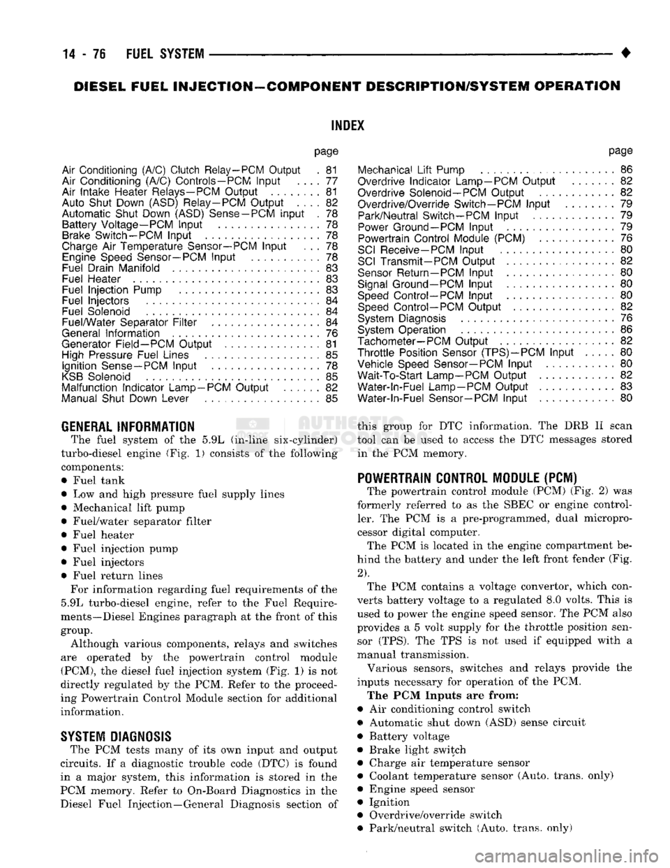
The powertrain control module (PCM) (Fig. 2) was
formerly referred to as the SBEC or engine control ler. The PCM is a pre-programmed, dual micropro
cessor digital computer. The PCM is located in the engine compartment be
hind the battery and under the left front fender (Fig.
2).
The PCM contains a voltage convertor, which con
verts battery voltage to a regulated 8.0 volts. This is used to power the engine speed sensor. The PCM also
provides a 5 volt supply for the throttle position sensor (TPS). The TPS is not used if equipped with a
manual transmission.
Various sensors, switches and relays provide the
inputs necessary for operation of the PCM.
The PCM Inputs are from:
9
Air conditioning control switch
• Automatic shut down (ASD) sense circuit
• Battery voltage
• Brake light switch • Charge air temperature sensor ® Coolant temperature sensor (Auto, trans, only)
• Engine speed sensor
• Ignition
• Overdrive/override switch
• Park/neutral switch (Auto, trans, only)
Page 896 of 1502
•
FUEL
SYSTEM
14-77
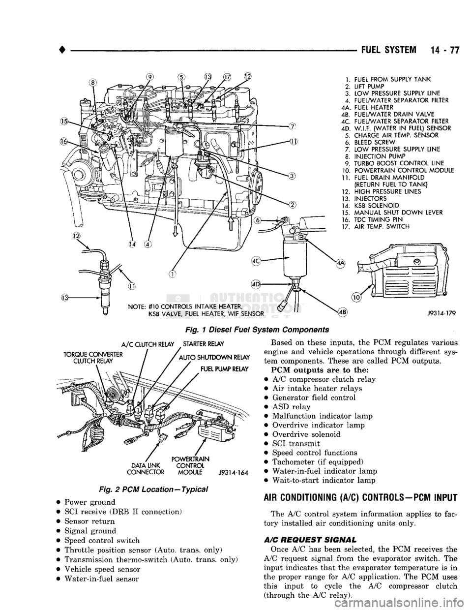
FUEL FROM SUPPLY TANK
LIFT
PUMP
LOW
PRESSURE
SUPPLY LINE
FUEL/WATER SEPARATOR FILTER
4A. FUEL HEATER
4B. FUEL/WATER DRAIN VALVE
FUEL/WATER SEPARATOR FILTER
W.I.F. (WATER
IN
FUEL) SENSOR
CHARGE
AIR
TEMP. SENSOR
BLEED
SCREW
LOW
PRESSURE
SUPPLY LINE
INJECTION PUMP
TURBO BOOST CONTROL LINE POWERTRAIN CONTROL MODULE
FUEL DRAIN MANIFOLD
(RETURN FUEL
TO
TANK)
HIGH
PRESSURE
LINES
INJECTORS
KSB
SOLENOID
MANUAL SHUT DOWN LEVER
TDC TIMING
PIN
AIR TEMP. SWITCH
NOTE: #10 CONTROLS INTAKE HEATER,
KSB
VALVE, FUEL HEATER,
WIF
SENSOR
J9314-179
Fig.
1
Diesel
Fuel
System
Components
TORQUE CONVERTER CLUTCH RELAY
A/C
CLUTCH RELAY STARTER RELAY
AUTO SHUTDOWN RELAY FUEL PUMP RELAY DATA UNK
CONNECTOR POWERTRAIN
CONTROL
MODULE
J9314-164
Fig.
2 PCM Location—Typical Power ground
SCI receive (DRB II connection)
Sensor return
Signal ground
Speed control switch
Throttle position sensor (Auto, trans, only)
Transmission thermo-switch (Auto, trans, only)
Vehicle speed sensor
Water-in-fuel sensor Based on these inputs, the PCM regulates various
engine and vehicle operations through different sys
tem components. These are called PCM outputs.
PCM outputs are to the:
• A/C compressor clutch relay
• Air intake heater relays
• Generator field control
• ASD relay
• Malfunction indicator lamp
• Overdrive indicator lamp
• Overdrive solenoid
• SCI transmit
• Speed control functions
• Tachometer (if equipped)
• Water-in-fuel indicator lamp • Wait-to-start indicator lamp
AIR CONDITIONING
(A/C)
CONTROLS-PCM
INPUT
The A/C control system information applies to fac
tory installed air conditioning units only.
A/C
REQUEST SIGNAL
Once A/C has been selected, the PCM receives the
A/C request signal from the evaporator switch. The input indicates that the evaporator temperature is in
the proper range for A/C application. The PCM uses this input to cycle the A/C compressor clutch (through the A/C relay).
Page 897 of 1502
14-78
FUEL SYSTEM
• If
the A/C low
pressure switch opens (indicating
a
low refrigerant level),
the PCM
will
not
receive
an
A/C select signal.
The PCM
will then remove
the
ground from
the A/C
relay. This will deactivate
the
A/C compressor clutch.
If evaporator switch opens, (indicating that evapo
rator
is not in
proper temperature range),
PCM
will
not receive
the A/C
request signal.
The PCM
will
then remove
the
ground from
the A/C
relay, deacti
vating
the A/C
compressor clutch.
AUTOMATIC SHUT DOWN
(ASD)
SENSE-PCM
INPUT
A
12
volt signal
at
this input indicates
to the PCM
that
the ASD has
been activated.
The ASD
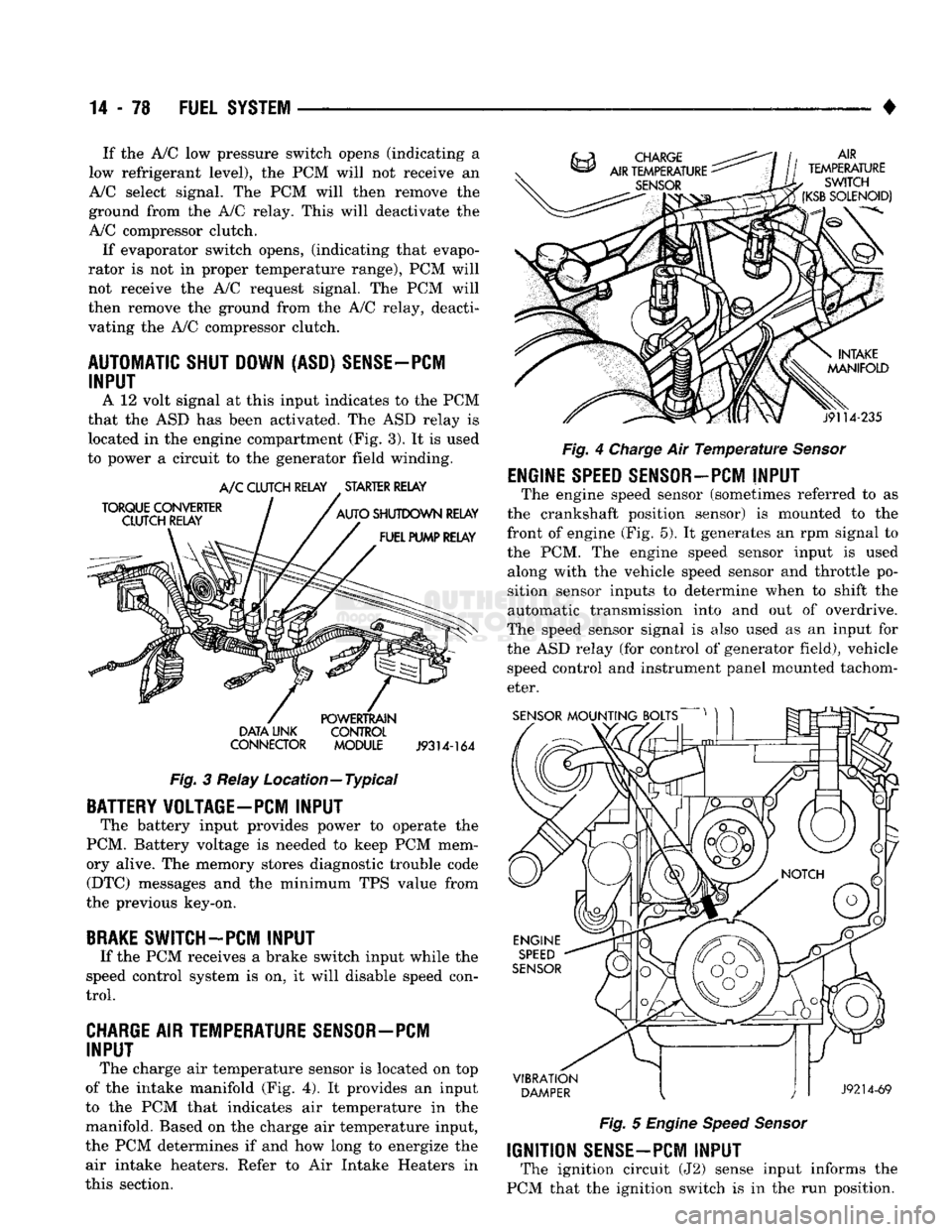
relay
is
located
in the
engine compartment
(Fig.
3).
It is
used
to power
a
circuit
to the
generator field winding.
TORQUE
CONVERTER
CLUTCH RELAY A/C
CLUTCH RELAY
.
STARTER RELAY
AUTO
SHUTDOWN
RELAY
FUEL PUMP RELAY
DATA
LINK
CONNECTOR
POWERTRAIN
CONTROL
MODULE
J9314-164
Fig.
3
Relay Location—Typical
BATTERY VOLTAGE-PC! INPUT
The battery input provides power
to
operate
the
PCM. Battery voltage
is
needed
to
keep
PCM
mem
ory alive.
The
memory stores diagnostic trouble code (DTC) messages
and the
minimum
TPS
value from
the previous key-on,
BRAKE
SWITCH-PCM INPUT
If
the PCM
receives
a
brake switch input while
the
speed control system
is on, it
will disable speed con
trol.
CHARGE AIR TEMPERATURE SENSOR—PCM INPUT
The charge
air
temperature sensor
is
located
on top
of
the
intake manifold
(Fig. 4). It
provides
an
input
to
the PCM
that indicates
air
temperature
in the
manifold. Based
on the
charge
air
temperature input,
the
PCM
determines
if and how
long
to
energize
the
air intake heaters. Refer
to Air
Intake Heaters
in
this section. AIR
TEMPERATURE
SWITCH
(KSB
SOLENOID)
j9114-235
Fig.
4
Charge
Air
Temperature Sensor
ENGINE
SPEED
SENSOR-PCM
INPUT
The engine speed sensor (sometimes referred
to as
the crankshaft position sensor)
is
mounted
to the
front
of
engine
(Fig. 5). It
generates
an rpm
signal
to
the
PCM. The
engine speed sensor input
is
used along with
the
vehicle speed sensor
and
throttle
po
sition sensor inputs
to
determine when
to
shift
the
automatic transmission into
and out of
overdrive.
The speed sensor signal
is
also used
as an
input
for
the
ASD
relay
(for
control
of
generator field), vehicle speed control
and
instrument panel mounted tachom
eter.
SENSOR
MOUNTING BOLTS
VIBRATION
DAMPER
J9214-69
Fig.
5
Engine Speed Sensor
IGNITION
SENSE-PCM
INPUT
The ignition circuit
(J2)
sense input informs
the
PCM that
the
ignition switch
is in the run
position.