1993 DODGE TRUCK door lock
[x] Cancel search: door lockPage 515 of 1502
8W
- 40
WIRING DIAGRAMS
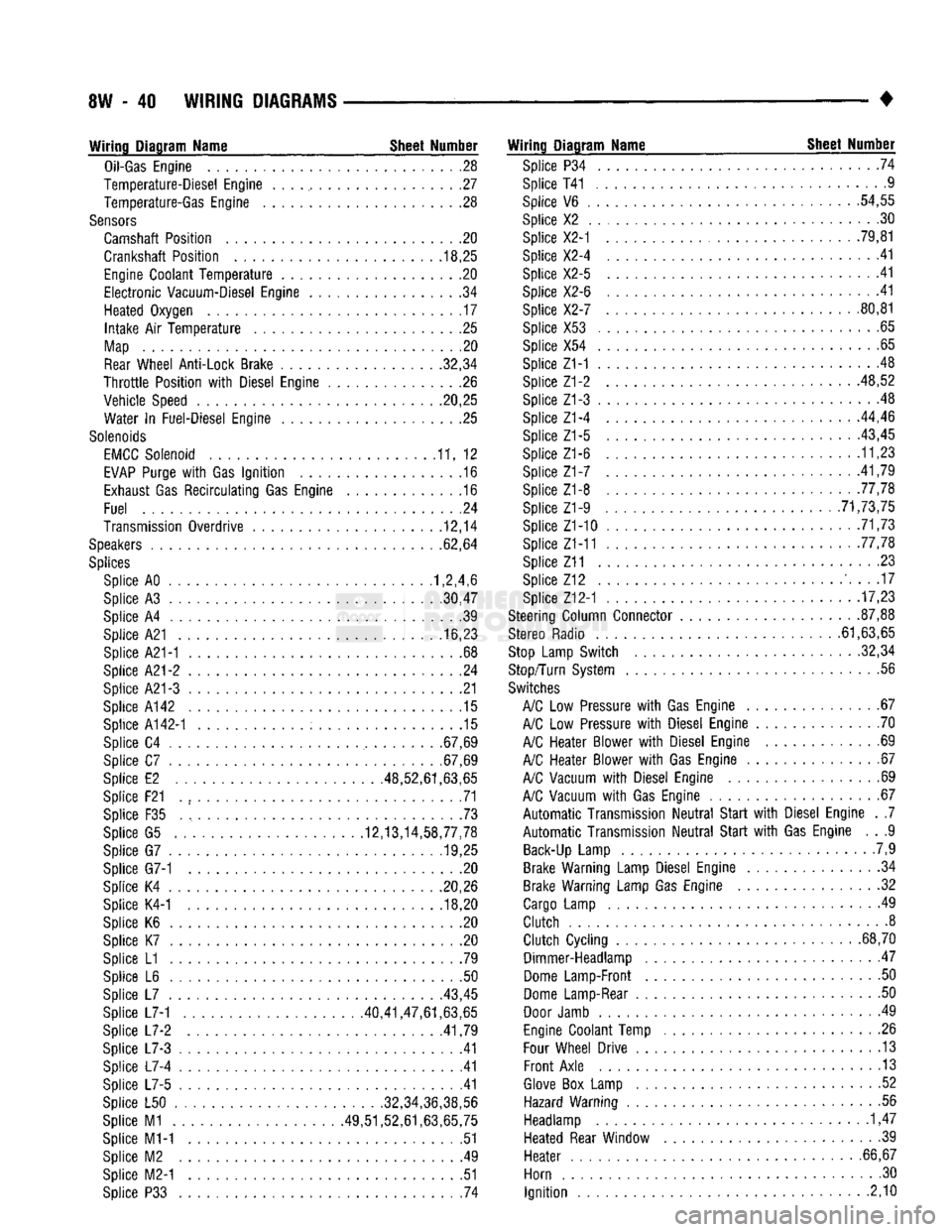
Wiring Diagram Name Sheet Number
Oil-Gas
Engine
28
Temperature-Diesel Engine
. . . ., 27
Temperature-Gas Engine
. .28
Sensors
Camshaft Position
. . .20
Crankshaft Position
. .
.18,25
Engine
Coolant
Temperature
20
Electronic
Vacuum-Diesel Engine
. .34
Heated Oxygen
17
Intake
Air
Temperature
25
Map
20
Rear
Wheel Anti-Lock Brake 32,34
Throttle
Position
with
Diesel Engine
26
Vehicle Speed .20,25 Water
In
Fuel-Diesel Engine
25
Solenoids
EMCC
Solenoid
11, 12
EVAP
Purge
with
Gas
Ignition
.16
Exhaust
Gas
Recirculating
Gas Engine
.16
Fuel
.24
Transmission Overdrive
12,14
Speakers
62,64
Splices
Splice AO 1,2,4,6
Splice
A3
30,47
Splice
A4 39
Splice A21
16,23
Splice A21-1
. .68
Splice
A21-2 24
Splice A21-3
21
Splice A142
.15
Splice
A142-1 15
Splice
C4
.67,69
Splice
C7
.67,69
Splice
E2
.48,52,61,63,65
Splice F21
. , 71
Splice
F35 73
Splice
G5
12,13,14,58,77,78 Splice
G7
........... .19,25
Splice G7-1
. . .20
Splice
K4
20,26 Splice K4-1
.... ..... ; . 18,20
Splice
K6 , 20
Splice
K7 .20
Splice
L1 .79
Splice
L6 . .50
Splice
L7
43,45
Splice L7-1 40,41,47,61,63,65
Splice
L7-2
.41,79
Splice
L7-3 .41
Splice
L7-4 41
Splice
L7-5 .41
Splice
L50
......
.
........... .32,34,36,38,56
Splice
M1
49,51,52,61,63,65,75 Splice M1-1
51
Splice
M2 . .49
Splice M2-1
.51
Splice
P33 . 74
Wiring Diagram Name Sheet Number
Splice
P34 .... .74
Splice T41 ..............
.9
Splice
V6 . .
.54,55
Splice
X2 . .30
Splice X2-1
. . . .
.79,81
Splice X2-4
41
Splice X2-5
.41
Splice X2-6
.... .41
Splice X2-7
80,81
Splice X53
.65
Splice
X54
..........
. . 65
Splice Z1-1
.48
Splice Z1-2 48,52
Splice Z1-3
. . 48
Splice Z1-4
...
.44,46
Splice
Z1-5 ..... . . . .
-43,45
Splice Z1-6
11,23
Splice
Z1-7 .
.41,79
Splice Z1-8 77,78 Splice Z1-9
. .
............ .71,73,75
Splice Z1-10
. 71,73
Splice Z1-11 .77,78
Splice Z11
23
Splice
Z12 ' 17
Splice Z12-1
17,23
Steering Column Connector
.
87,88
Stereo Radio 61,63,65
Stop
Lamp Switch 32,34
Stop/Turn System
.56
Switches
A/C
Low
Pressure
with
Gas Engine
67
A/C
Low
Pressure
with
Diesel Engine
70
A/C
Heater Blower
with
Diesel Engine
69
A/C
Heater Blower
with
Gas Engine
67
A/C
Vacuum
with
Diesel Engine
69
A/C
Vacuum
with
Gas Engine
67
Automatic
Transmission
Neutral
Start
with
Diesel Engine
. .7
Automatic
Transmission
Neutral
Start
with
Gas Engine
. . .9
Back-Up
Lamp
.7,9
Brake Warning Lamp Diesel Engine
34
Brake Warning Lamp Gas Engine
. .32
Cargo
Lamp
49
Clutch
8
Clutch
Cycling
...
.68,70 Dimmer-Headlamp
47
Dome
Lamp-Front
. .50
Dome
Lamp-Rear
50
Door
Jamb
. 49
Engine
Coolant Temp
.26
Four
Wheel Drive
13
Front
Axle
13
Glove
Box
Lamp
. .52
Hazard Warning
.56
Headlamp
1,47
Heated Rear Window
39
Heater
. .
.66,67
Horn
.30
Ignition
2,10
Page 516 of 1502
WIRING
DIAGRAMS
SW - 41
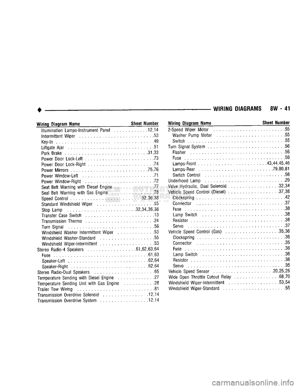
Wiring
Diagram Name _ Sheet Number
Illumination
Lamps-Instrument Panel ........... .12,14
Intermittent
Wiper ......................... .53
Key-In
. . . . . . . .49
Liftgate
Ajar
............................ .51
Park
Brake
.31,33
Power
Door Lock-Left ....................... .73
Power
Door Lock-Right .74
Power
Mirrors .75,76
Power
Window-Left 71
Power
Window-Right . .72
Seat
Belt
Warning
with
Diesel Engine 77
Seal
Belt
Warning
with
Gas Engine .78
Speed
Control
........... ,32,36,38
Standard
Windshield Wiper . .55
Stop
Lamp .32,34,36,38
Transfer
Case
Switch . 13
Transmission
Thermo ....................... .24
Turn Signal .56
Windshield Washer
Intermittent
Wiper . .53
Windshield Washer-Standard .55 Windshield
Wiper-Intermittent
53
Stereo
Radio-4 Speakers .61,62,63,64
Fuse
.61,63
Speaker-Left ......... ............ 62,64
Speaker-Right
. .62,64
Stereo
Radio-Dual Speakers .65
Temperature Sending
with
Diesel Engine . .27
Temperature Sending
Unit
with
Gas Engine .......... .28
Trailer
Tow Wiring 81
Transmission
Overdrive Solenoid ............... .12,14
Transmission
Overdrive System 12,14
Wiring
Diagram Name ^ Sheet Number
2-Speed
Wiper Motor 55
Washer
Pump
Motor
....................... .55
Switch 55
Turn
Signal
System
.......................... .56
Flasher
56
Fuse
.56
Lamps-Front
43,44,45,46
Lamps-Rear
. 79,80,81
Switch
Control
56
Underhood
Lamp 29
Valve
Hydraulic, Dual Solenoid .32,34
Vehicle
Speed
Control
(Diesel) .37,38
Clockspring 42 Connector .37
Fuse
................................. .38
Lamp
Switch . . .38
Resistor
.38
Servo
• .37
Vehicle
Speed
Control
(Gas) .35,36
Clockspring 36
Connector .35
Fuse
......... 36
Lamp
Switch .36
Resistor
.36
Servo
. 35
Vehicle
Speed
Sensor
.20,25,26 Wide Open
Throttle
Cutout Relay . .68,70
Windshield
Wiper-intermittent
...... ....... .53,54
Windshield Wiper-Standard 55
Page 517 of 1502
8W
- 42
WIRING DIAGRAMS
-J_
ENGINE
=
GROUND
BODY
—
GROUND
BATTERY
-A
15
22WT-
^—
FUSIBLE LINK
(22WT)
(LEFT
FRONT WHEELHOUSE) FUSIBLE LINK
(18GY)
(LEFT
FRONT WHEELHOUSE)
All
6BK/GY FUSIBLE LINK
{1000)50/120 AMP
(LEFT
FRONT WHEELHOUSE) A15
16PK
13#-ZI
L9
18BK WT
i
HAZARD
FLASHER
SH
56
IT-
FUSE
#13
20 AMP
O
FUSE
#4
|
ft 20 AMP
F33
18PK
RD
A3
12RD WT A3
12RD WT
4-
CHARGING
SYSTEM
SH
3,4,5.6
FUSE
#6 20 AMP
FUSE
#5
J—1| 20 AMP
F33
18PK
RD
HORNS
SH
30
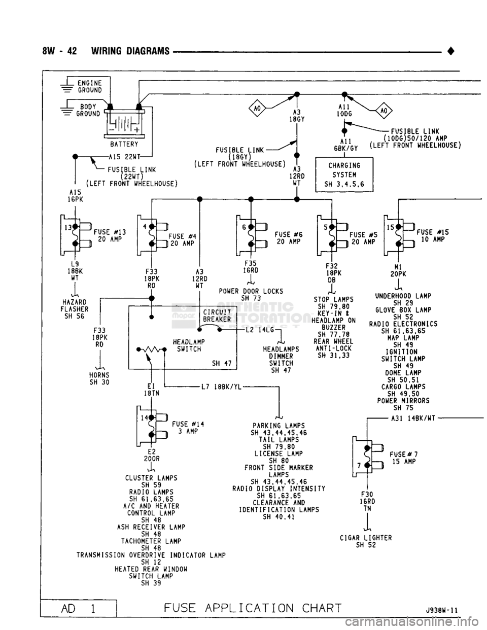
POWER DOOR LOCKS
SH
73
CIRCUIT
BREAKER
HEADLAMP
•VWf
SWITCH
EI
18TN
SH
47
-L2 HEADLAMPS
DIMMER SWITCH
SH
47
F32
18PK
DB
I
STOP LAMPS
SH
79,80
KEY-IN
I
HEADLAMP
ON
BUZZER
SH
77.78
REAR
WHEEL ANTI-LOCK
SH
31.33
FUSE
#15
10 AMP
L7
18BK/YL-
3
FUSE
#14
D 3AMP
E2
200R
X
CLUSTER LAMPS
SH
59
RADIO LAMPS
SH
61.63.65
A/C
AND
HEATER CONTROL LAMP
SH
48
ASH
RECEIVER LAMP
SH
48
TACHOMETER LAMP
SH
48
TRANSMISSION OVERDRIVE INDICATOR LAMP
SH
12
HEATED REAR WINDOW SWITCH LAMP
SH
39
PARKING LAMPS
SH
43.44.45,46
TAIL
LAMPS
SH
79.80
LICENSE
LAMP
SH
80
FRONT SIDE MARKER
LAMPS
SH
43.44.45.46
RADIO DISPLAY INTENSITY
SH
61.63.65
CLEARANCE
AND
IDENTIFICATION
LAMPS
SH
40.41
UNDERHOOD LAMP
SH
29
GLOVE
BOX
LAMP
SH
52
RADIO ELECTRONICS
SH
61.63.65
MAP LAMP
SH
49
IGNITION
SWITCH LAMP
SH
49
DOME LAMP
SH
50.51
CARGO
LAMPS
SH
49.50
POWER MIRRORS
SH
75
A31
14BK/WT
-
7*3
LI FUSE
#7
2h-i
15 AMP
F30
16RD TN
1
CIGAR LIGHTER
SH
52
AD
1
FUSE
APPLICATION CHART
J938W-U
Page 564 of 1502
•
WIRING
DIAGRAMS
8W - 89
TO
TRANSMISSION
V
OVERDRIVE CONTROL SWITCH
(SEE
SH 12)
TO
TRANSMISSION
OVERDRIVE CONTROL SWITCH
(SEE
SH
12)GAS
(SEE
SH
M)DIESEL Zl
18BK
E2
200R
E2
200R 200R
Zl
18BK
TO SEAT
X
BELT SWITCH
^(SEE
SH
77,76)
TO RIGHT
PRINTED
CIRCUIT BOARD CONNECTOR
(SEE
SH 60)
BLACK
-Zl
22BK
fTO KEY-IN LAMP
>
(SEE SH 49)
„ TO
CHASSIS
{
WIRING
^(SEE
SH 41,79)
€
TO
CARGO LAMP
j
SWITCH
(SEE
SH 49)
Zl
12BK
TO HEATED REAR
WINDOW SWITCH
(SEE
SH 39)
(SPORT
UTILITY
ONLY)
TO
RADIO
[SEE
SH
61,63,65)
PROVISION
FOR
TACHOMETER (NEAR FUSE BLOCK)
(OIESEL)
BLACK
TO
PCM II
(SEE
SH 22)
TO
TURN
SIGNAL
FLASHER
(SEE
SH 56)
BLACK
-J
MO
TO MESSAGE
CENTER
(DIESEL)
(SEE
SH 57)
GROUND
TO BRAKE
SWITCH
(SEE
SH
32.34, 36,38)
J938W-U
TO
MAP
LAMP
AND READING
(SEE
SH 49)
TO POWER DOOR LOCKS
(SEE
SH 73)
TO POWER MIRRORS
(SEE
SH 75)
TO POWER WINDOWS
(SEE
SH 71)
A/C
AND
HEATER SWITCH LAMP
TO
INTERMITTENT
WIPER MODULE
(SEE
SH 53)
TO CIGAR
LIGHTER
(SEE
SH 52)
TO
A/C AND
HEATER WIRING
(SEE
SH 67,69)
TO GLOVE
BOX
LAMP
(SEE
SH 52)
TO HEATEO
REAR
WINDOW
(SEE
SH 39)
SPORT
UTILITY
ONLY)
HEADLAMP
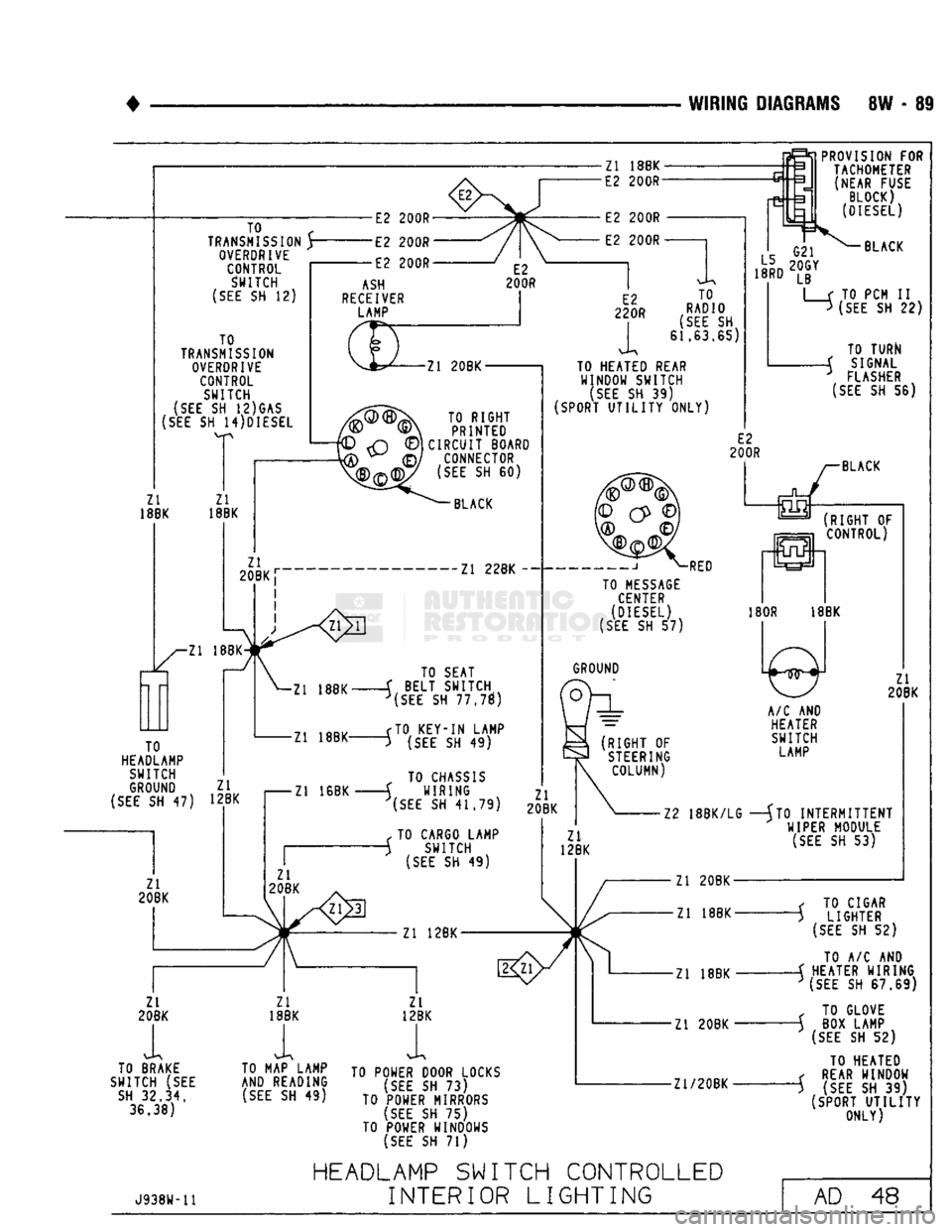
SWITCH CONTROLLED
INTERIOR
LIGHTING
AD
48
Page 589 of 1502
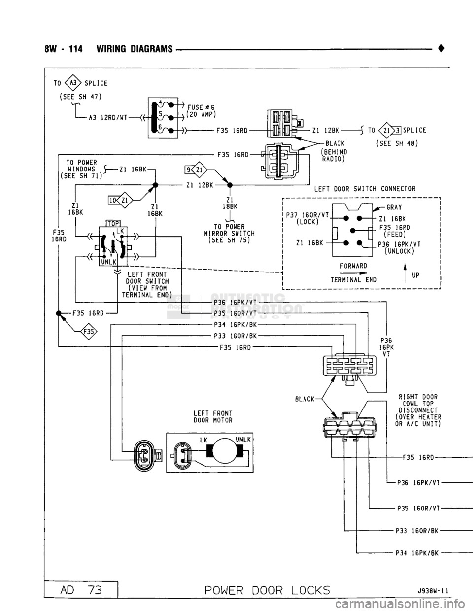
8W - 114 WIRING
DIAGRAMS
TO
SPLICE
(SEE
SH 47) A3
12RD/WT
FUSE
#6
(20 AMP)
F35 16RD 3 Zl 12BK-TO POWER „
WINDOWS 5 Zl 16BK—.
(SEE
SH 71)
Zl
16BK 10
16RD Zl
16BK
i LK
Ml
UNLK F35 16R0 G=
v 0:
•BLACK
(BEHIND RADIO) -5 TO
(SEE
SH 48)
LEFT DOOR SWITCH CONNECTOR
' LEFT FRONT
DOOR
SWITCH (VIEW FROM
TERMINAL END)
1^—F35
16RD 1 TO POWER
MIRROR
SWITCH
(SEE
SH 75) P37
160R/VT
(LOCK)
Zl 16BK r-GRAY
Zl 16BK F35 16RD (FEED)
P36
16PK/VT
(UNLOCK)
FORWARD
TERMINAL END
UP
•P36
16PK/VT
•P35
160R/VT
•P34
16PK/BK P33 160R/BK
—F35
16RD P36
16PK VT LEFT FRONT
DOOR
MOTOR RIGHT DOOR
COWL TOP
DISCONNECT
(OVER HEATER
OR
A/C
UNIT)
F35 16RD-
P36 16PK/VT• P35
160R/VT
P33 160R/BK P34 16PK/BK
AD
73
POWER
DOOR
LOCKS
J938W-11
Page 590 of 1502
![DODGE TRUCK 1993 Service Repair Manual
•
WIRING DIAGRAMS 8W - 115 RIGHT DOOR SWITCH CONNECTOR
P33
160R/BK (LOCK)
P35
160R/VT
] —E
FORWARD
TERMINAL END
-BLUE
P36 16PK/VT
• F35 16RD
P34 1BPK/BK (UNLOCK)
t
UP
y- DODGE TRUCK 1993 Service Repair Manual
•
WIRING DIAGRAMS 8W - 115 RIGHT DOOR SWITCH CONNECTOR
P33
160R/BK (LOCK)
P35
160R/VT
] —E
FORWARD
TERMINAL END
-BLUE
P36 16PK/VT
• F35 16RD
P34 1BPK/BK (UNLOCK)
t
UP
y-](/manual-img/12/56922/w960_56922-589.png)
•
WIRING DIAGRAMS 8W - 115 RIGHT DOOR SWITCH CONNECTOR
P33
160R/BK (LOCK)
P35
160R/VT
] —E
FORWARD
TERMINAL END
-BLUE
P36 16PK/VT
• F35 16RD
P34 1BPK/BK (UNLOCK)
t
UP
y-—•
• •—'
RIGHT FRONT DOOR SWITCH /
(VIEW FROM /
TERMINAL END) / BLACK—^
fTOPl
/
VLK
P36 P34
16PK 16PK VT BK F35 16RD-
P36 16PK/VT -J
P35
160R/VT-
P33
160R/BK- P34 16PK/BK
J938W-11 P34
16PK
BK
F35
16RD P35
160R VT
P33
160R/BK-P34 16PK/BK
POWER
DOOR LOCKS RIGHT FRONT
DOOR
MOTOR
^ LK X—\UNLK
to AD 74
Page 1159 of 1502
21 - 158
TRANSMISSION
OVERHAUL—32RH
•
OVERHAUL SERVICE
INFORMATION
Inspect all the transmission bushings during over
haul. Bushing condition is important as worn, scored
bushings contribute to low pressures, clutch slip and accelerated wear of other components. Do not replace
bushings as a matter of course. Replace bushings
only when actually worn or scored. Use recommended tools to replace bushings. The
tools are sized and designed to remove, install and seat bushings correctly, The bushing replacement
tools are included in Bushing Tool Set C-3887-B. The
tool set is manufactured by the Miller Tool Co. and is available through the dealer tool program. Pre-sized service bushings are available for re
placement purposes. Only the sun gear bushings are
not serviced. Low cost of the sun gear assembly
makes it easier to simply replace the gear and bush
ings as an assembly. Heli-Coil inserts are recommended for repairing
damaged, stripped or worn threads in aluminum
parts.
These inserts are available from most automo
tive jobbers. Stainless steel inserts are preferred. The use of crocus cloth is permissible where neces
sary, providing it is used carefully. When used on
valves, use extreme care to avoid rounding off sharp
edges.
Sharp edges are vital as they prevent foreign
matter from getting between the valve and valve
bore.
Do not reuse oil seals, gaskets, seal rings, or
O-rings during overhaul. Replace these parts as a
matter of course. Also do not reuse snap rings or
E-clips that are bent or distorted. Replace these parts as well.
Lubricate transmission parts with Mopar ATF
Plus,
Type 7176, or Dexron II™ transmission fluid during overhaul and assembly.
Use Ru-Glyde or Door Eze to lubricate clutch pis
ton seals. Use petroleum jelly to lubricate O-rings and thrust washers. Petroleum jelly can also be used
to hold parts in place during reassembly.
TRANSMISSION
CASE
CLEAN1N8
AND
INSPECTION
Clean the case in a solvent tank. Flush the case
bores and fluid passages thoroughly with solvent. Dry the case and all fluid passages with compressed
air. Be sure all solvent is removed from the case and
that all fluid passages are clear. Do not use shop towels or rags to dry the case
(or any other transmission component) unless
they are made from lint-free materials. Lint will
readily adhere to case surfaces and transmission
components and will circulate throughout the
transmission after assembly. A sufficient quan
tity of lint can block fluid passages and interfere
with valve body operation. Inspect the case for cracks, porous spots, worn
bores,
or damaged threads. Damaged threads can be repaired with Helicoil thread inserts. However, the
case will have to be replaced if it exhibits any type of
damage or wear.
Lubricate the front band adjusting screw threads
with petroleum jelly and thread the screw part-way into the case. Be sure the screw turns freely.
Remount the case in Repair Stand C-3750-B after
cleaning and inspection.
OVERRUNNING CLUTCH-LOW-REVERSE
DRUM-REAR
SUPPORT OVERHAUL
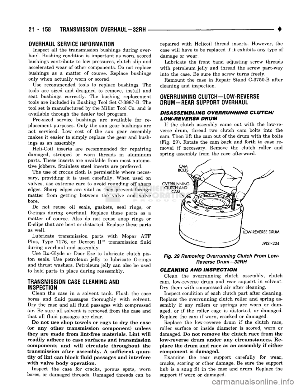
DISASSEMBLING OVERRUNNING CLUTCH/ LOW-REVERSE DRUM
If the clutch assembly came out with the low-re
verse drum, thread two clutch cam bolts into the cam. Then lift the cam out of the drum with the bolts (Fig. 29). Rotate the cam back and forth to ease re
moval if necessary. Remove the clutch roller and spring assembly from the race afterward.
Fig, 29 Removing Overrunning Clutch From Low- Reverse Drum—32RH
CLEANING AND INSPECTION Clean the overrunning clutch assembly, clutch
cam, low-reverse drum and rear support in solvent.
Dry them with compressed air after cleaning. Inspect condition of each clutch part after cleaning.
Replace the overrunning clutch roller and spring as sembly if any rollers or springs are worn or dam
aged, or if the roller cage is distorted, or damaged.
Replace the cam if worn, cracked or damaged.
Replace the low-reverse drum if the clutch race,
roller surface or inside diameter is scored, worn or damaged. Do not remove the clutch race from the
low-reverse drum under any circumstances. Re place the drum and race as an assembly if either component is damaged.
Examine the rear support carefully for wear,
cracks, scoring or other damage. Be sure the support
hub is a snug fit in the case and drum. Replace the support if worn or damaged.
Page 1170 of 1502
•
TRANSMISSION
OVERHAUL—32RH
21 - 111
J9121-150
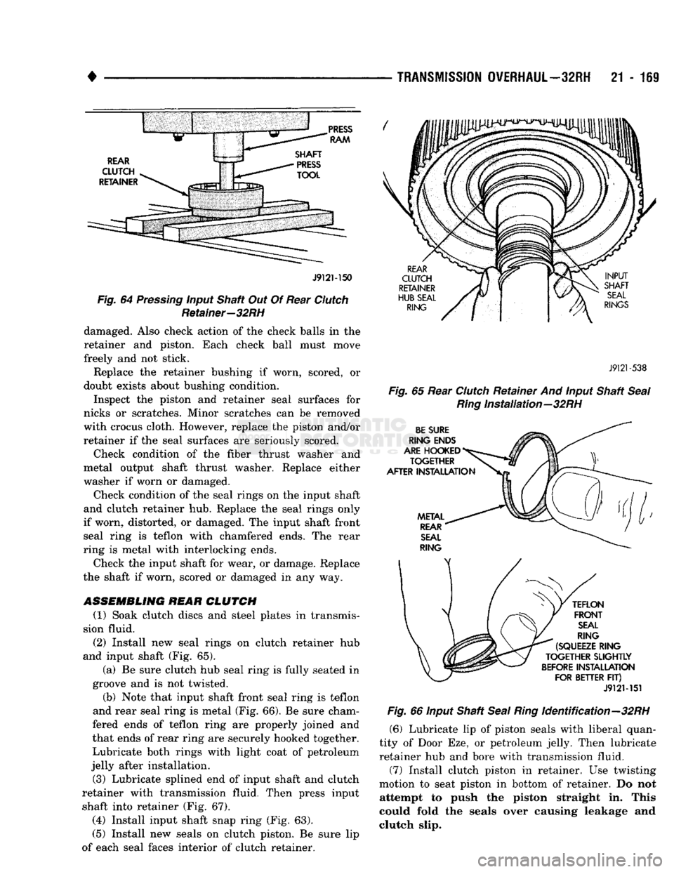
Fig. 64 Pressing input Shaft Out Of Rear Clutch Retainer—32RH damaged. Also check action of the check balls in the
retainer and piston. Each check ball must move
freely and not stick.
Replace the retainer bushing if worn, scored, or
doubt exists about bushing condition.
Inspect the piston and retainer seal surfaces for
nicks or scratches. Minor scratches can be removed
with crocus cloth. However, replace the piston and/or
retainer if the seal surfaces are seriously scored.
Check condition of the fiber thrust washer and
metal output shaft thrust washer. Replace either
washer if worn or damaged.
Check condition of the seal rings on the input shaft
and clutch retainer hub. Replace the seal rings only
if worn, distorted, or damaged. The input shaft front seal ring is teflon with chamfered ends. The rear
ring is metal with interlocking ends.
Check the input shaft for wear, or damage. Replace
the shaft if worn, scored or damaged in any way.
ASSEMBLING REAR
CLUTCH
(1) Soak clutch discs and steel plates in transmis
sion fluid.
(2)
Install new seal rings on clutch retainer hub
and input shaft (Fig. 65).
(a) Be sure clutch hub seal ring is fully seated in
groove and is not twisted.
(b) Note that input shaft front seal ring is teflon
and rear seal ring is metal (Fig. 66). Be sure cham
fered ends of teflon ring are properly joined and
that ends of rear ring are securely hooked together. Lubricate both rings with light coat of petroleum
jelly after installation.
(3) Lubricate splined end of input shaft and clutch
retainer with transmission fluid. Then press input shaft into retainer (Fig. 67).
(4)
Install input shaft snap ring (Fig. 63).
(5) Install new seals on clutch piston. Be sure lip
of each seal faces interior of clutch retainer.
J9121
-538
Fig.
65 Rear Clutch Retainer And input Shaft
Seal Ring
Installation—32RH
J912M51 Fig. 66 input Shaft Seal
Ring
Identification—32RH
(6) Lubricate lip of piston seals with liberal quan
tity of Door Eze, or petroleum jelly. Then lubricate
retainer hub and bore with transmission fluid. (7) Install clutch piston in retainer. Use twisting
motion to seat piston in bottom of retainer. Do not attempt to push the piston straight in. This
could fold the seals over causing leakage and
clutch slip.