1993 DODGE TRUCK door lock
[x] Cancel search: door lockPage 51 of 1502
0
- 32
LUBRICATION
AND
MAINTENANCE
•
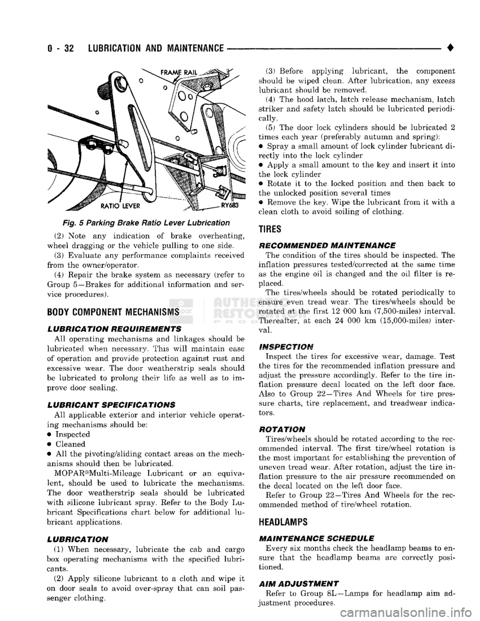
Fig.
5 Parking Brake Ratio Lever Lubrication (2) Note any indication of brake overheating,
wheel dragging or the vehicle pulling to one side.
(3) Evaluate any performance complaints received
from the owner/operator. (4) Repair the brake system as necessary (refer to
Group 5—Brakes for additional information and ser
vice procedures).
BODY
COMPONENT
MECHANISMS
LUBRICATION REQUIREMENTS
All operating mechanisms and linkages should be
lubricated when necessary. This will maintain ease of operation and provide protection against rust and
excessive wear. The door weatherstrip seals should
be lubricated to prolong their life as well as to im prove door sealing.
LUBRICANT SPECIFICATIONS
All applicable exterior and interior vehicle operat
ing mechanisms should be:
• Inspected • Cleaned
• All the pivoting/sliding contact areas on the mech anisms should then be lubricated.
MOPAR®Multi-Mileage Lubricant or an equiva
lent, should be used to lubricate the mechanisms.
The door weatherstrip seals should be lubricated
with silicone lubricant spray. Refer to the Body Lu
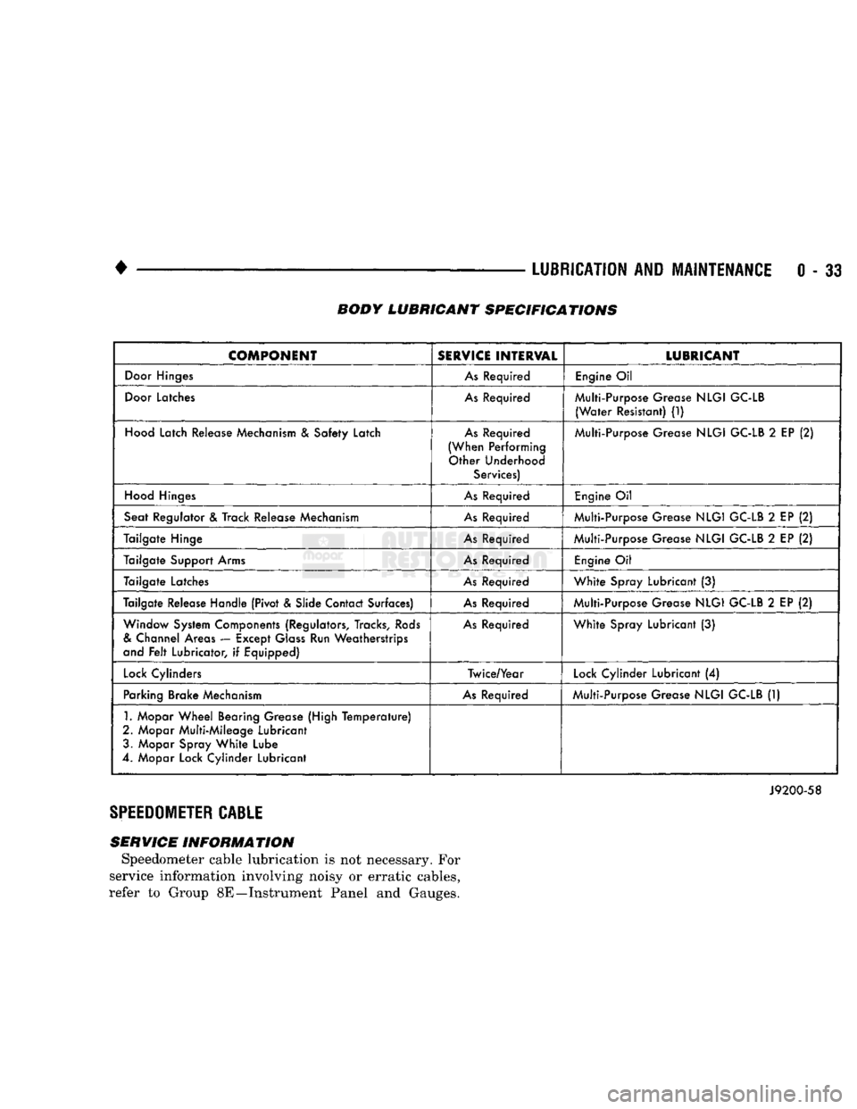
bricant Specifications chart below for additional lu
bricant applications.
LUBRICATION
(1) When necessary, lubricate the cab and cargo
box operating mechanisms with the specified lubri
cants.
(2) Apply silicone lubricant to a cloth and wipe it
on door seals to avoid over-spray that can soil pas
senger clothing. (3) Before applying lubricant, the component
should be wiped clean. After lubrication, any excess
lubricant should be removed.
(4) The hood latch, latch release mechanism, latch
striker and safety latch should be lubricated periodi
cally.
(5) The door lock cylinders should be lubricated 2
times each year (preferably autumn and spring): • Spray a small amount of lock cylinder lubricant di
rectly into the lock cylinder
• Apply a small amount to the key and insert it into
the lock cylinder • Rotate it to the locked position and then back to
the unlocked position several times
• Remove the key. Wipe the lubricant from it with a
clean cloth to avoid soiling of clothing.
TIRES
RECOMMENDED MAINTENANCE
The condition of the tires should be inspected. The
inflation pressures tested/corrected at the same time as the engine oil is changed and the oil filter is re
placed.
The tires/wheels should be rotated periodically to
ensure even tread wear. The tires/wheels should be
rotated at the first 12 000 km (7,500-miles) interval.
Thereafter, at each 24 000 km (15,000-miles) inter
val.
INSPECTION
Inspect the tires for excessive wear, damage. Test
the tires for the recommended inflation pressure and adjust the pressure accordingly. Refer to the tire in
flation pressure decal located on the left door face. Also to Group 22—Tires And Wheels for tire pressure charts, tire replacement, and treadwear indica
tors.
ROTATION
Tires/wheels should be rotated according to the rec
ommended interval. The first tire/wheel rotation is
the most important for establishing the prevention of uneven tread wear. After rotation, adjust the tire in
flation pressure to the air pressure recommended on
the decal located on the left door face.
Refer to Group 22—Tires And Wheels for the rec
ommended method of tire/wheel rotation.
HEADLAMPS
MAINTENANCE SCHEDULE
Every six months check the headlamp beams to en
sure that the headlamp beams are correctly posi
tioned.
AIM
ADJUSTMENT
Refer to Group 8L—Lamps for headlamp aim ad
justment procedures.
Page 52 of 1502
•
LUBRICATION
AND
MAINTENANCE
0 - 33 BODY LUBRICANT SPECIFICATIONS
COMPONENT
SERVICE
INTERVAL
LUBRICANT
Door
Hinges
As
Required
Engine
Oil
Door
Latches
As
Required Multi-Purpose Grease
NLGI
GC-LB
(Water
Resistant)
(1)
Hood
Latch Release Mechanism
&
Safety Latch
As
Required
(When Performing Other Underhood Services) Multi-Purpose Grease
NLGI
GC-LB
2
EP
(2)
Hood
Hinges
As
Required
Engine
Oil
Seat Regulator
&
Track Release Mechanism
As
Required Multi-Purpose Grease
NLGI
GC-LB
2
EP
(2)
Tailgate Hinge
As
Required Multi-Purpose Grease
NLGI
GC-LB
2
EP
(2)
Tailgate Support Arms
As
Required
Engine
Oil
Tailgate Latches
As
Required
White
Spray Lubricant
(3)
Tailgate Release Handle (Pivot & Slide Contact Surfaces)
As
Required Multi-Purpose Grease
NLGI
GC-LB
2
EP
(2)
Window System Components (Regulators, Tracks,
Rods
&
Channel Areas — Except
Glass
Run Weatherstrips
and
Felt
Lubricator,
if
Equipped)
As
Required
White
Spray Lubricant
(3)
Lock
Cylinders Twice/Year
Lock
Cylinder Lubricant
(4)
Parking Brake Mechanism
As
Required Multi-Purpose Grease
NLGI
GC-LB
(1)
1.
Mopar
Wheel
Bearing Grease (High
Temperature)
2. Mopar Multi-Mileage Lubricant 3. Mopar Spray
White
Lube
4. Mopar Lock Cylinder Lubricant
J9200-58
SPEEDOMETER
CABLE
SERVICE INFORMATION Speedometer cable lubrication is not necessary. For
service information involving noisy or erratic cables,
refer to Group 8E—Instrument Panel and Gauges.
Page 275 of 1502
DIAGNOSIS
PRELIMINARY
CHECKS
ENGINE COOLING SYSTEM OVERHEATING Establish what driving conditions caused the com
plaint. Abnormal loads on the cooling system such as
the following may be the cause:
1.
PROLONGED IDLE, VERY HIGH AMBI
ENT TEMPERATURE, SLIGHT TAIL WIND AT
IDLE, SLOW TRAFFIC, TRAFFIC JAMS, HIGH SPEED OR STEEP GRADES.
Driving techniques that avoid overheating are:
• Idle with A/C off when temperature gauge is at
end of normal range. * Increasing engine speed for more air flow is recom
mended.
2.
TRAILER TOWING: Consult Trailer Towing section of owners manual.
Do not exceed limits.
3.
AIR CONDITIONING; ADD-ON OR AFTER
MARKET: A maximum cooling package should have been or
dered with vehicle if add-on or after market A/C is
SYMPTOM AND ACTION
SYMPTOM
installed. If not, maximum cooling system compo
nents should be installed for model involved per
manufacturer's specifications.
4.
RECENT SERVICE OR ACCIDENT RE
PAIR:
Determine if any recent service has been performed
on vehicle that may effect cooling system. This may
be:
• Engine adjustments (incorrect timing)
• Slipping engine accessory drive belt(s) • Brakes (possibly dragging)
• Changed parts. Incorrect water pump or pump ro
tating in wrong direction due to belt not correctly
routed
• Reconditioned radiator or cooling system refilling (possibly under filled or air trapped in system).
If investigation reveals none of the above as a
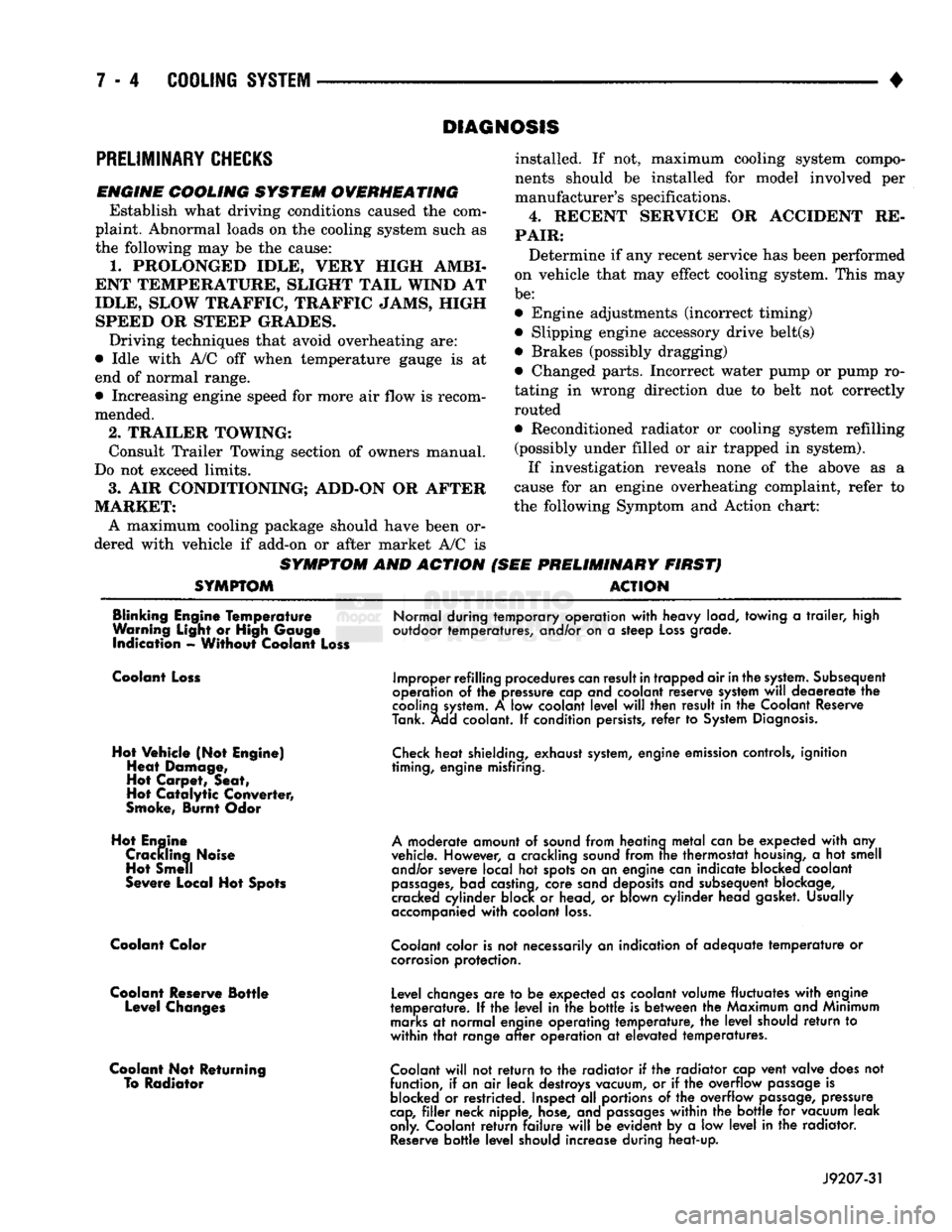
cause for an engine overheating complaint, refer to
the following Symptom and Action chart:
PRELIMINARY FIRST) ACTION
Blinking Engine Temperature
Warning Light or High Gauge indication - Without Coolant Loss
Normal during temporary operation
with
heavy load, towing
a
trailer,
high
outdoor temperatures, and/or on
a
steep
Loss
grade.
Coolant Loss
Hot Vehicle (Not Engine) Heat Damage,
Hot Carpet, Seat,
Hot
Catalytic
Converter,
Smoke, Burnt Odor
Hot Engine Crackling Noise Hot Smell
Severe Local Hot Spots
Coolant Color
Coolant Reserve Bottle Level Changes
Coolant Not Returning To Radiator
Improper refilling procedures
can
result
in
trapped air
in
the
system.
Subsequent
operation
of the
pressure cap and coolant reserve system
will
deaereate
the
cooling
system.
A low
coolant
level
will
then result
in the
Coolant Reserve
Tank. Add coolant.
If
condition persists,
refer
to
System
Diagnosis.
Check
heat shielding, exhaust
system,
engine emission controls, ignition
timing, engine misfiring.
A
moderate amount
of
sound from heating
metal
can
be
expected
with
any
vehicle. However,
a
crackling sound from
trie
thermostat
housing,
a hot
smell and/or severe local
hot
spots on
an
engine can indicate blocked coolant
passages,
bad castina, core sand deposits and subsequent blockage,
cracked cylinder block
or
head,
or
blown cylinder head gasket. Usually
accompanied
with
coolant
loss.
Coolant
color is
not
necessarily
an
indication
of
adequate
temperature
or
corrosion
protection.
Level changes
are to be
expected as coolant volume fluctuates
with
engine
temperature.
If the
level
in the
bottle
is
between
the
Maximum and Minimum
marks
at
normal engine operating temperature,
the
level
should
return
to
within
that
range
after
operation
at
elevated temperatures.
Coolant
will
not
return
to the
radiator
if the
radiator cap vent valve does
not
function,
if
an
air
leak destroys vacuum,
or if the
overflow
passage
is
blocked
or
restricted. Inspect
all
portions
of the
overflow
passage,
pressure
cap,
filler
neck nipple, hose, and
passages
within
the
bottle
for
vacuum leak
only. Coolant
return
failure
will
be
evident
by a low
level
in the
radiator.
Reserve
bottle
level
should increase during heat-up.
J9207-31
Page 325 of 1502
8A
- 4
ELECTRICAL
•
IGNITION
OFF
DRAW
(IOD)
Ignition off draw refers to power being drained
from the battery with the ignition turned off. A nor
mal vehicle electrical system will draw from 5 to 20
milliamps. A vehicle that has not been operated for
an extended period of time (approximately 20 days)
may discharge the battery to an inadequate level.
Battery drain should not exceed approximately 20
MA (20 milliamps = 0.020 amps). The 20 MA are needed to supply PCM memory,
digital clock memory, and ETR (electronically tuned
radio) memory. Excessive battery drain is caused by items left
turned on, internally shorted generator, or intermit
tent short in wiring.
If the IOD is excessive (over 20 milliamperes), the
defect must be found and corrected before replacing a
battery. In most cases the battery can be charged and returned to service.
TEST PROCEDURE Testing for higher amperage IOD must be per
formed first to prevent damage to most milliamp
meters.
Verify that all electrical accessories are OFF. Turn
off all lights, remove ignition key, and close all
doors.
If the vehicle is equipped with electronic acces
sories (illuminated entry, high line radio), allow the
systems to automatically shut off (time out), up to 3
minutes.
(1) After determining that the underhood lamp is
operating properly then disconnect bulb. (2) Disconnect negative cable from battery.
(3) Connect a typical 12 volt test light (low watt
age bulb) between the negative cable clamp and the
battery negative terminal. The test light may light brightly for up to 3 min
utes or may not light at all (depending on the elec
trical equipment). The term brightly being used
throughout the following tests, implies the bright ness of the test light will be the same as if it were
connected across the battery.
The test light must be securely clamped to the neg
ative cable and battery terminal. If the test light be
comes disconnected during any of the IOD test, the electronic timer function will be activated and all
tests must be repeated.
(4) After 3 minutes, the test light should turn OFF
or be DIMLY lit (depending on the electrical equip
ment).
If the test light remains brightly lit do not
disconnect it. Remove each fuse or circuit breaker (refer to Group 8 - Wiring Diagrams) until test light
is either OFF or DIMLY lit. This will eliminate the
higher amperage draw.
If test light is still bright after disconnecting each
fuse and circuit breaker, disconnect the wiring har ness from the generator. Refer to Generator Testing
in this group. Do not disconnect the test light. After higher amperage IOD has been corrected, low
amperage IOD may be checked.
It is now safe to install milliamp meter to check for
low amperage IOD.
(5) With test light still connected, securely clamp
an ammeter between battery negative terminal and
negative battery cable.
If the test light or the milliamp meter circuit is
broken the various timer circuits will start. Do
not open any doors or turn on any electrical ac cessories with the test light disconnected or the
meter may be damaged.
(6) Disconnect test light. The current draw should
not exceed 0.020 amp. If it exceeds 20 milliamps iso
late each circuit by removing circuit breakers and
fuses.
The meter reading drops once the high current
problem is found. Repair this section of the circuit,
whether it is a wiring short or component failure.
BATTERY
OPEN CIRCUIT VOLTAGE TEST
A battery voltage (no load) test will indicate the
state of charge of a battery that will pass the Battery
Load Test described in this section. Before proceed
ing with this test or the Battery Load Test the
battery must be completely charged as de scribed in Battery Charging in this section. If a battery has a no load voltage reading of 12.4
volts or greater but will not endure a load test, it is
defective and should be replaced. Refer to Group 8B,
Battery/Starter Service for instructions. To test bat
tery no load voltage, perform the following operation: (1) Before measuring open circuit voltage, the sur
face charge must be removed from plates. Turn head lights on for 15 seconds then allow up to 5 minutes
for voltage to stabilize. (2) Remove both battery cables, negative first.
(3) Using a voltmeter connected to the battery
posts,
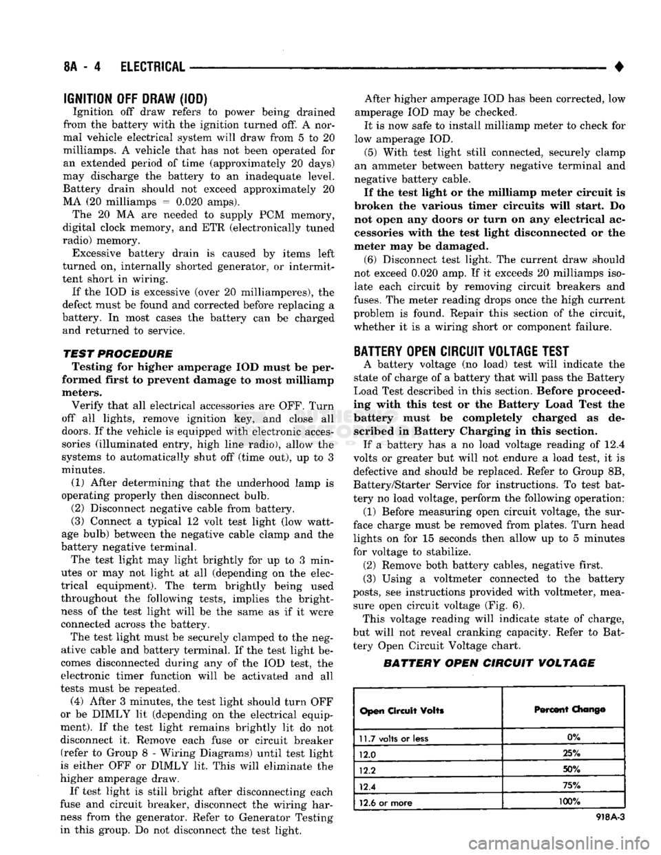
see instructions provided with voltmeter, mea sure open circuit voltage (Fig. 6). This voltage reading will indicate state of charge,
but will not reveal cranking capacity. Refer to Bat
tery Open Circuit Voltage chart.
BATTERY OPEN CIRCUIT VOLTAGE
Open
Circuit
Volts
Percent
Chang©
11.7
volts
or
less
0%
12.0 25%
12.2 50%
12.4 75%
12.6
or more 100%
918A-3
Page 399 of 1502
8E
- 18
INSTRUMENT PANEL
AND
GAUGES
—
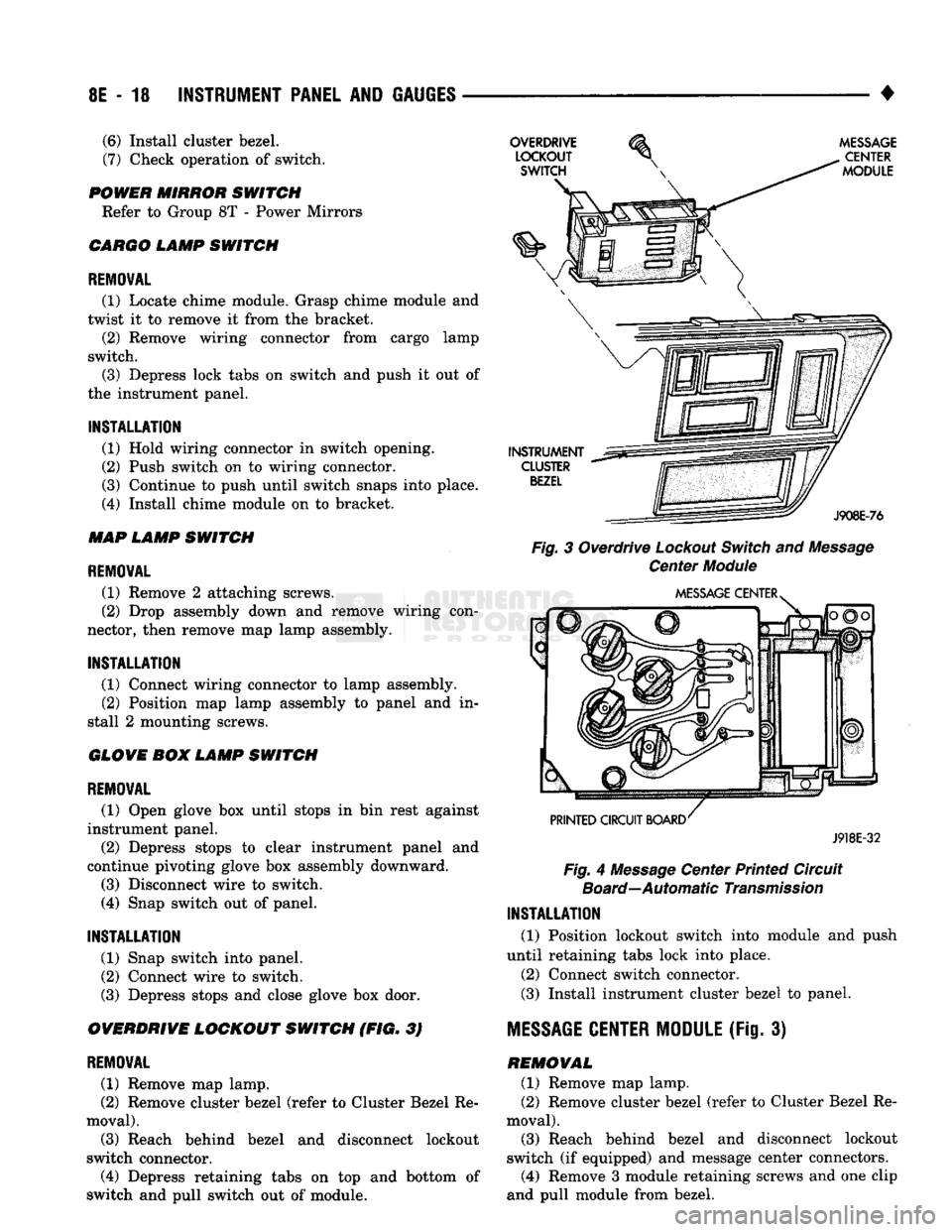
•
Fig.
3 Overdrive
Lockout
Switch
and
Message
Center
Module
J918E-32
Fig.
4
Message
Center Printed Circuit
Board—Automatic
Transmission
INSTALLATION
(1) Position lockout switch into module and push
until retaining tabs lock into place.
(2) Connect switch connector.
(3)
Install instrument cluster bezel to panel.
MESSAGE
CENTER MODULE
(Fig. 3) REMOVAL (1) Remove map lamp.
(2) Remove cluster bezel (refer to Cluster Bezel Re
moval).
(3)
Reach behind bezel and disconnect lockout
switch (if equipped) and message center connectors.
(4)
Remove 3 module retaining screws and one clip
and pull module from bezel.
(6)
Install cluster bezel.
(7)
Check operation of switch.
POWER MIRROR SWITCH Refer to Group 8T - Power Mirrors
CARGO LAMP SWITCH
REMOVAL
(1) Locate chime module. Grasp chime module and
twist it to remove it from the bracket. (2) Remove wiring connector from cargo lamp
switch.
(3)
Depress lock tabs on switch and push it out of
the instrument panel.
INSTALLATION
(1) Hold wiring connector in switch opening.
(2) Push switch on to wiring connector.
(3)
Continue to push until switch snaps into place.
(4)
Install chime module on to bracket.
MAP LAMP SWITCH
REMOVAL
(1) Remove 2 attaching screws.
(2) Drop assembly down and remove wiring con
nector, then remove map lamp assembly.
INSTALLATION
(1) Connect wiring connector to lamp assembly. (2) Position map lamp assembly to panel and in
stall 2 mounting screws.
GLOVE BOX LAMP SWITCH
REMOVAL
(1) Open glove box until stops in bin rest against
instrument panel.
(2) Depress stops to clear instrument panel and
continue pivoting glove box assembly downward.
(3)
Disconnect wire to switch.
(4)
Snap switch out of panel.
INSTALLATION
(1) Snap switch into panel.
(2) Connect wire to switch.
(3)
Depress stops and close glove box door.
OVERDRIVE LOCKOUT SWITCH (FIG. 3)
REMOVAL
(1) Remove map lamp.
(2) Remove cluster bezel (refer to Cluster Bezel Re
moval).
(3)
Reach behind bezel and disconnect lockout
switch connector.
(4)
Depress retaining tabs on top and bottom of
switch and pull switch out of module.
Page 402 of 1502
•
INSTRUMENT PANEL AND GAUGES 8E - 21
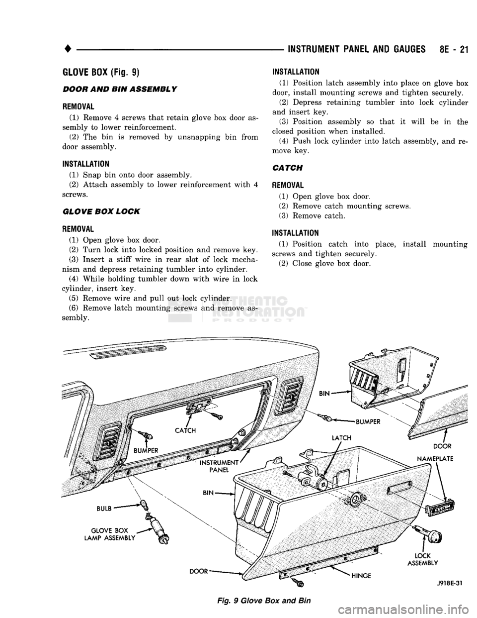
GLOVE
BOX
(Fig.
9)
BOOH
AND BIN
ASSEMBLY
REMOVAL
(1) Remove
4
screws that retain glove
box
door
as
sembly
to
lower reinforcement. (2)
The bin is
removed
by
unsnapping
bin
from
door assembly.
INSTALLATION
(1) Snap
bin
onto door assembly.
(2) Attach assembly
to
lower reinforcement with
4
screws.
GLOVE
BOM
LOCK
REMOVAL
(1) Open glove
box
door.
(2)
Turn lock into locked position
and
remove
key.
(3) Insert
a
stiff wire
in
rear slot
of
lock mecha
nism
and
depress retaining tumbler into cylinder.
(4) While holding tumbler down with wire
in
lock
cylinder, insert
key.
(5)
Remove wire
and
pull
out
lock cylinder.
(6) Remove latch mounting screws
and
remove
as
sembly.
INSTALLATION
(1) Position latch assembly into place
on
glove
box
door, install mounting screws
and
tighten securely. (2) Depress retaining tumbler into lock cylinder
and insert
key.
(3) Position assembly
so
that
it
will
be in the
closed position when installed. (4) Push lock cylinder into latch assembly,
and re
move
key.
CATCH
REMOVAL
(1) Open glove
box
door.
(2) Remove catch mounting screws.
(3) Remove catch.
INSTALLATION
(1) Position catch into place, install mounting
screws
and
tighten securely.
(2) Close glove
box
door.
Fig.
9
Giove
Box
and
Bin
Page 460 of 1502
•
POWER DOOR LOCKS
8P - 1
POWER DOOR LOCKS
CONTENTS
SERVICE
PROCEDURES
page
..
2
TEST PROCEDURES
page
..
1
equipped,
can be
by operating
the
GENERAL
INFORMATION
Both doors, when electrically
locked
or
unlocked electrically switch
on a
door panel. Both doors
can be
locked
or
unlocked mechanically
with
the
locking knob regardless
of
electrical locking and unlocking actuation.
TEST
PROCEDURES
The right
and
left front door
on all
vehicles
can be
locked
or
unlocked mechanically from
the
outside
with
the key or
electrically
as
described above.
The
left door
can
also
be
unlocked
by
actuation
of
the
in
side remote door handle.
FUSE
TEST
Locate
the
fuse
in
fuse cavity number
6 on the
fuse
block.
If
fuse
is
blown, replace
it. If
fuse blows again refer
to
Switch Test
and
Voltage Test procedures
to
find
the
short circuit.
SWITCH TEST
For switch testing, remove
the
switch from
its
mounting location. Using
an
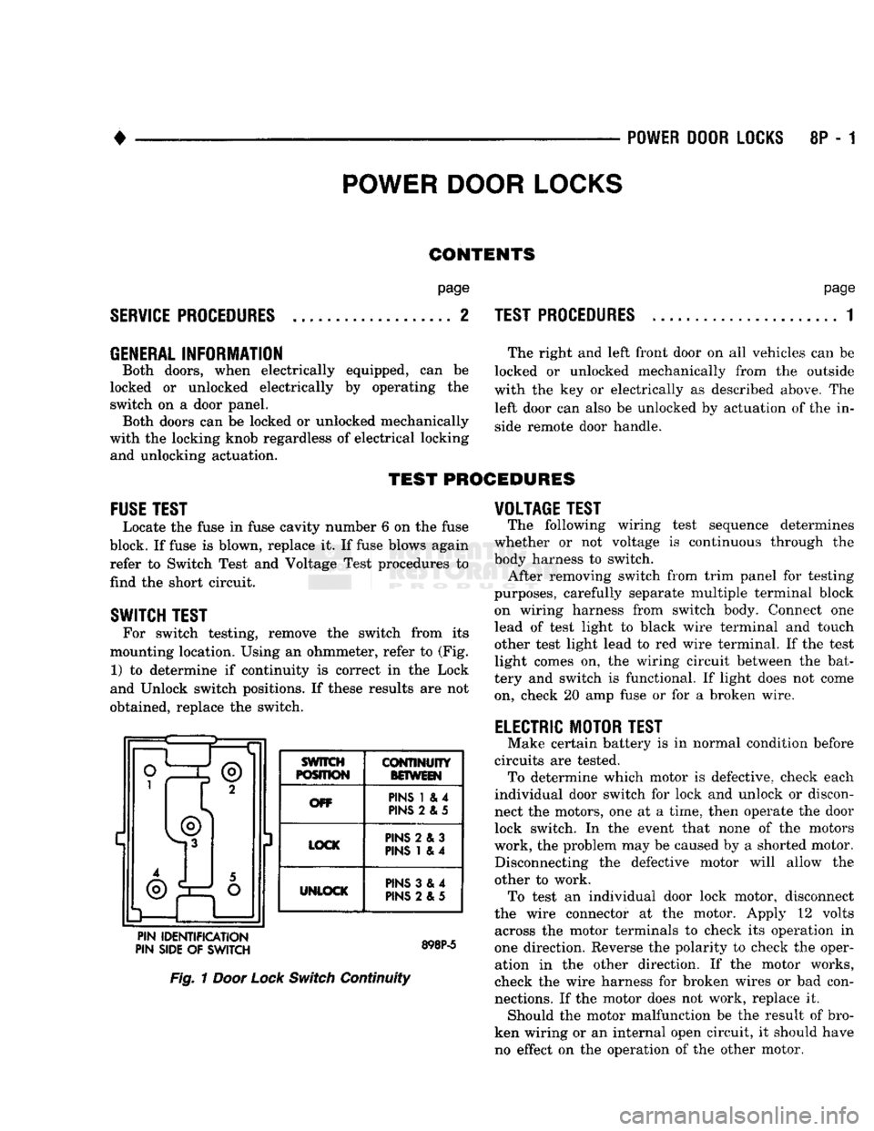
ohmmeter, refer
to
(Fig. 1)
to
determine
if
continuity
is
correct
in the
Lock
and Unlock switch positions.
If
these results
are not
obtained, replace
the
switch. ®
3 SWITCH
POSITION
CONTINUITY
BOWEIN
OFF PINS
1 & 4
PINS
2 & 5
LOCK PINS
2 & 3
PINS
1 & 4
UNLOCK
PINS
3 &4
PINS
2 &5
PIN IDENTIFICATION
PIN SIDE
OF
SWITCH
Fig.
1
Door Lock
Switch
Continuity
VOLTAGE TEST
The following wiring test sequence determines
whether
or not
voltage
is
continuous through
the
body harness
to
switch. After removing switch from trim panel
for
testing
purposes, carefully separate multiple terminal block
on wiring harness from switch body. Connect
one
lead
of
test light
to
black wire terminal
and
touch other test light lead
to red
wire terminal.
If
the test
light comes
on, the
wiring circuit between
the
bat
tery
and
switch
is
functional.
If
light does
not
come
on, check
20 amp
fuse
or for a
broken wire.
ELECTRIC MOTOR TEST
Make certain battery
is in
normal condition before
circuits
are
tested. To determine which motor
is
defective, check each
individual door switch
for
lock
and
unlock
or
discon
nect
the
motors,
one at a
time, then operate
the
door lock switch.
In the
event that none
of the
motors
work,
the
problem may
be
caused
by a
shorted motor. Disconnecting
the
defective motor will allow
the
other
to
work. To test
an
individual door lock motor, disconnect
the wire connector
at the
motor. Apply
12
volts across
the
motor terminals
to
check
its
operation
in
one direction. Reverse
the
polarity
to
check
the
oper ation
in the
other direction.
If the
motor works,
check
the
wire harness
for
broken wires
or bad
con
nections.
If
the motor does
not
work, replace
it.
Should
the
motor malfunction
be the
result
of
bro
ken wiring
or an
internal open circuit,
it
should have no effect
on the
operation
of
the other motor.
Page 461 of 1502
8P
- 2 POWER DOOR LOCKS
• SERVICE PROCEDURES
DOOR LOCK MOTOR REPLACEMENT
REMOVAL
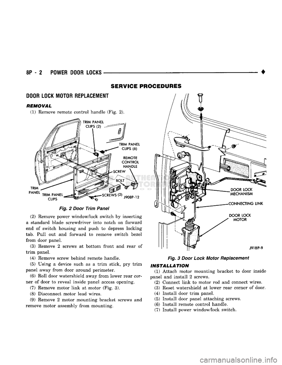
(1) Remove remote control handle (Fig. 2).
TRIM
PANEL
TRIM
PANEL
CLIPS
(6)
REMOTE
CONTROL
HANDLE
SCREW
TRIM
PANEL
CLIPS
J908P-12
Fig.
2
Door
Trim
Panel
(2) Remove power window/lock switch by inserting
a standard blade screwdriver into notch on forward
end of switch housing and push to depress locking
tab.
Pull out and forward to remove switch bezel
from door panel.
(3) Remove 2 screws at bottom front and rear of
trim panel.
(4) Remove screw behind remote handle.
(5) Using a device such as a trim stick, pry trim
panel away from door around perimeter.
(6) Roll door watershield away from lower rear cor
ner of door to reveal inside panel access opening.
(7) Remove motor link at motor (Fig. 3).
(8) Disconnect motor lead wires.
(9) Remove 2 motor mounting bracket screws and
remove motor assembly from mounting.
DOOR
LOCK
MOTOR
J918P-9
Fig.
3
Door
Lock
Motor Replacement
INSTALLATION
(1) Attach motor mounting bracket to door inside
panel and install 2 screws. (2) Connect link to motor rod and connect wires.
(3) Reset watershield at lower rear corner of door.
(4) Install door trim panel. (5) Install door panel attaching screws.
(6) Install remote control handle.
(7) Install power window/lock switch.