1993 DODGE TRUCK door lock
[x] Cancel search: door lockPage 1440 of 1502
•
HEATING
AND AIR
CONDITIONING
24 - 3
DIAGNOSTIC
PROCEDURES
INDEX
page
page ..
7
General Information
3
.
. 3
Heating System Output
3
Air
Conditioning System
Blower
Motor
GENERAL
INFORMATION
The reason for owner dissatisfaction must be thor
oughly understood before any attempt is made to re
pair or replace any parts. It must be determined if
the condition is the heater system, the refrigerant system, air conditioning air flow or related to the
compressor. After confirming the condition, a func
tional test is suggested using the diagnostic charts.
After the condition has been properly diagnosed and corrected, check out the complete system to assure
that it is performing satisfactorily. The following charts have been developed for quick
reference. If the step by step method used is not com pletely understood, refer to the correct section of the Service Manual for detailed explanations.
HEATING
SYSTEM
OUTPUT
WARNING:
IF
VEHICLE
HAS
BEEN
RUN
RECENTLY,
WAIT
15
MINUTES
BEFORE
REMOVING
CAP, THEN
PLACE
A RAG
OVER
THE CAP AND
TURN
IT TO
THE
FIRST
STOP.
ALLOW
PRESSURE
TO
ESCAPE
THROUGH
THE
OVERFLOW
TUBE
AND
WHEN
THE
SYSTEM
STABILIZES,
REMOVE
THE CAP
COM
PLETELY.
Check the radiator coolant level, drive belt tension,
engine vacuum line connections, radiator air flow and radiator fan operation. Start engine and bring to
normal operating temperature (refer to Group 7,
Cooling System).
Engine coolant is provided to the heater system by
2 heater hoses. With engine idling at normal operat
ing temperature, set the heater control to maximum
heat, defrost and high blower setting. Using a test
thermometer, check the air temperature coming from
the defroster outlets (refer to Temperature Reference Chart).
Should the temperature not meet the minimum
values shown, refer to Heater Diagnosis (Mechanical)
for possible causes and corrections.
(1) Remove radiator pressure cap.
(2) Drain 1 pint of coolant from the radiator.
(3) Warm the engine to operating temperature by
idling for 20 minutes, with the pressure cap off. Idle longer if working outdoors in cold temperatures. (4) With the engine idling, place a thermometer
into the coolant in the radiator filler neck.
TEMPERATURE REFERENCE CHART
AMBIENT
MINIMUM
HEATER SYSTEM
TEMPERATURE
AIR OUTLET
TEMPERATURE
°C
°F
°C
°F
15.5 60 62.2 144
21.1 70
63.8 147
26.6 80
65.5 150
32.2 90 67.2 153
J9124-11
(5) Engine coolant temperature should stabilize at
no lower than 86°C (187°F) or 4°C (8°F) below the
thermostat opening temperature. This should happen during the vehicle operating cycle.
(6) Instrument panel control in HEAT mode.
(7) Set to high blower speed.
(8) Temperature lever to maximum heat position.
BLOWER
MOTOR
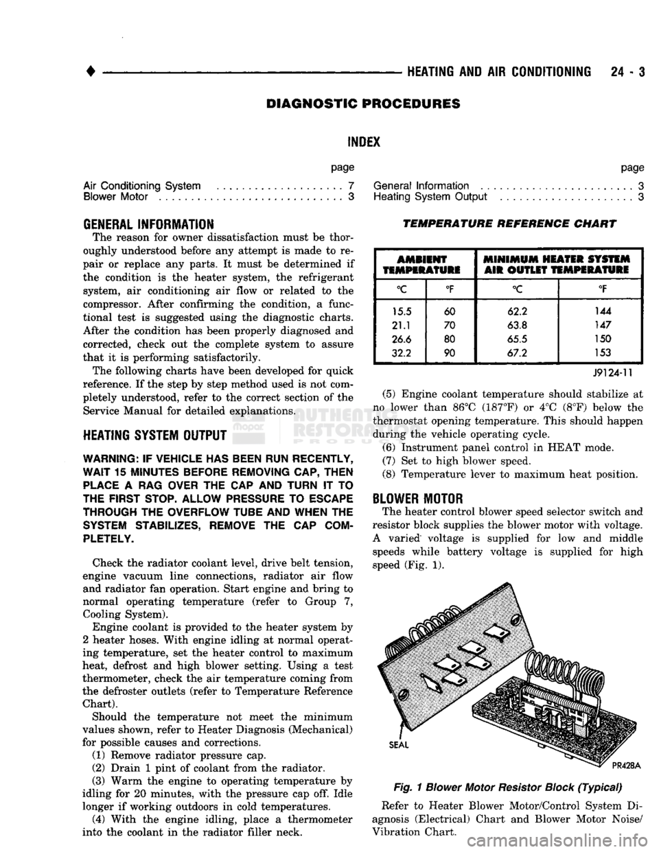
The heater control blower speed selector switch and
resistor block supplies the blower motor with voltage.
A varied voltage is supplied for low and middle speeds while battery voltage is supplied for high
speed (Fig. 1).
Fig.
1
Blower
Motor
Resistor
Block
(Typical)
Refer to Heater Blower Motor/Control System Di
agnosis (Electrical) Chart and Blower Motor Noise/
Vibration Chart.
Page 1466 of 1502
HEATING
AND
AIR
CONDITIONING
24 - 29
CLIMATE CONTROL
SYSTEM
INDEX
page
Air Conditioner Distribution
and
Spot Cooler
Ducts-Center
. . 38
Air Conditioner Distribution
and
Spot Cooler
Ducts-Left Bi-Level
38
Air Conditioner Distribution
and
Spot Cooler
Ducts-Right
Bi-Level
38
Air
Outlet
Assemblies Right
Side
.............
38
Control Test
......
30
Defroster Duct
34
Electrical Controls
and
Circuits
30
Electronic Temperature Cycling Switch
37
Evaporator Control Unit
. . 34
GENERAL
INFORMATION
This
air
conditioner
is
designed specifically
for
con
ventional
cab
trucks with
the
heater-evaporator
package designed
to fit
under
the
instrument panel.
The system
is
manually controlled
by the
operator. Controls have been kept simple
for
ease
of
service and operation. In
the
blend
air
reheat
air
conditioning unit,
all
the
air
entering
the
system passes through
the
evap orator.
A
selected portion passes through
the
heater
core depending
on the
position
of the
blend
air
door.
The system controls
are
located
in the
center
of the
instrument panel within easy reach
of the
driver.
The combination electrical
and
vacuum switch con
trols
the
compressor clutch, mode
of
operation
and
blower. Modes
are Off, Max. A/C, A/C,
Vent, Heat and Defrost.
A
4-speed blower motor switch controls
the amount
of air
flow.
The
evaporator-heater pack age includes:
•
The
blower motor. • Intake duct with outside
air
recirculating door.
• Evaporator coil
• Heater core.
• Defroster discharge doors.
• Blower motor speed resistors.
• Vacuum harness.
• Vacuum actuators.
•
A/C air
outlets
to the
distribution ducts. Defrost, Heat,
A/C and
Vent modes automatically
supply
100%
outside
air.
The
air
distribution ducts supply
air
from
the
unit
to
4
panel mounted, fully directional, outlets.
The
faceplate
has 2
outlets
and 2 are
snapped into
the
panel
on the
right side. Satisfactory performance
of the air
conditioning
and heating system
is
dependent upon correct opera
tion
and
adjustment
of all
operating controls.
The in
spections, tests
and
adjustments should
be
used
to
locate
the
cause
of a
malfunction.
The
tests
in
this
page
Evaporator Heater Assembly
36
Expansion
(H)
Valve
37
Faceplate
32
General Information
. 29
Heater Assembly
. 33
Heater Control
32
Louver
Assemblies
39
Operation
of All
Controls
29
Resistor
Block
33
Temperature
and
Mode Control Cables
. 32
Vacuum
Actuators
36
Vacuum
Controls
and
Circuits
30
manual have been arranged
in a
logical sequence
that
has
proved
to be the
surest
and
shortest route
to
accurate diagnosis.
It is
recommended that they
be
followed
and
performed
in the
order they
are
pre sented.
OPERATION
OF ALL
CONTROLS
Operation must
be
tested
as
described
in the
fol
lowing sequence: (1) Inspect, test,
and
adjust compressor drive belt.
(2) Start engine
and
adjust engine speed
to 1,300
RPM.
Use a
reliable tachometer. (3) Move temperature control lever
to
Cool position
and mode lever
to A/C
position. (4)
The
inlet
air
door should
be
open
to
outside
air.
Open vehicle windows. (5) Test
the
blower operation
at all 4
speed posi
tions.
If the
blower does
not
operate correctly refer
to
Electrical Controls
and
Circuit. Leave
the
blower switch
in the
HIGH position.
(6)
The
compressor should
be
running
and the air
conditioning system
in
operation. In addition
to the six
position push button selector,
the
A/C
Heater control consists
of:
TEMPERATURE LEVER-Controls
the
tempera-.
ture
of the
discharge
air in all
modes except
MAX
A/C
and Off
when
the
vacuum operated water valve is closed. Moving
the
lever
to the
left provides cooler
air
and
moving
it to the
right provides warmer
air.
BLOWER SWITCH-The system blower
can be op
erated
at 4
speeds.
•
LOW at the
bottom. • MEDIUM
1 at the
lower center.
• MEDIUM
2 at the
upper center.
• HIGH
at the top
switch position. The blower will
be on and
operating
at the
speed
selected,
in all
push button positions except
Off.
AIR DIRECTIONAL VANES-Air
is
delivered
through
4
panel outlets.
The 4
outlets
are
adjustable
Page 1467 of 1502
24 - 30
HEATING
AND AIR
CONDITIONING
•
up,
down or to either side and can be shut off by
pushing the vanes up. Floor air is delivered through
the lower outlets.
VACUUM CONTROLS
AND
CIRCUITS
For an explanation of the vacuum and electrical
logic that controls the operation of the unit (Fig. 1
and Control Chart). MODES—The vacuum and electrical logic is deter
mined by the push button switch. The vacuum por
tion of the switch controls the water valve and
positions all doors in the unit except the blend air
door. The electrical portion of the switch controls the compressor and blower operation. The following is a
breakdown of the vacuum and electrical logic for each mode. Refer to Control Chart in this section.
OFF Vacuum application is as indicated in Fig. 1. The
inlet air door is closed to outside, open to recirculat
ing air. The mode door is in the A/C position. The
Heat/Defrost door is in the Heat position. The heater core coolant flow is
shut-off.
No air flows through the unit and the compressor
is idle because the blower and compressor clutch cir
cuits are open.
MAX A/C All of the doors are in the same position as they
are in Off. The Max. A/C mode merely closes the
electrical circuits to the blower motor and the com
pressor clutch. This mode is recommended for initial cool down, extreme outside humidity or high ambient
temperature.
A/C
This mode is recommended for use after the vehicle
has been cooled to the desired temperature. The vac
uum application at the outside-recirculating air door actuator is transferred to the rod side. This moves
the door away from the outside-air inlet and closes
the recirculating inlet. The water valve is open. All
other vacuum applications and door positions are the
same for the Max. A/C position. The blower motor and compressor are on.
VENT The vacuum circuit remains the same as in the
A/C position but the compressor clutch electrical cir
cuit is opened, preventing the compressor from oper ating. The blower motor is used to force outside air
into the passenger compartment through the A/C
outlets in the instrument panel.
HEAT
In the Heat mode the outside air door is open same
as A/C mode. Vacuum is applied to the top side of the air condi
tioning door actuator. This will close off the passage
to the air conditioning distribution duct and open the
passage to the heater/defroster duct. Since the heat er-defroster door is in the heat position, the full flow
of heated air goes through the heater outlets. A
small amount of heated air will bleed through the
defroster outlets. The water valve is open, the blower
switch is activated and the compressor is off.
DEFROST When the defrost mode is selected all conditions
are the same as for heater operation, except that no
vacuum is applied to the defrost door actuator. The defrost door is spring loaded to the defrost position.
The door opens the defroster outlets and partially closes off the heater outlets. The heater outlets are
left open far enough to direct about 30 percent of the
air to the floor. The other 70% is defrost air directed
to the windshield area. The compressor clutch will be engaged.
ELECTRICAL CONTROLS AND CIRCUITS
The electrical feed for the air conditioning circuit is
from 2 fuses in the fuse block. A 20 ampere fuse pro
tects the compressor clutch circuit, and a 30 ampere fuse protects the blower motor control circuit.
CONTROL TEST
Test operation of controls in the following manner.
(1) Inspect compressor drive belt. Adjust, if neces
sary. (2) Start engine. (3) Move temperature lever to extreme left (cool)
position. (4) Push A/C button.
(5)
Refer to Control Chart. Check position of doors,
operation of compressor clutch, blower motor and wa
ter valve. The water valve is open when there is no
vacuum to valve. (6) Check blower switch by moving it to all 4 posi
tions and noting air flow change. In case of malfunc
tion refer to Electrical Control Circuit. (7) Check operation of blend air door by moving
temperature lever from full warm toward cool posi
tion. Discharge air temperature should change with lever movement if the engine coolant is warm. (8) Repeat steps 5 and 6 in each push-button posi
tion. If actuation of the doors is slow or incomplete,
check for mechanical misalignment, binding or vac uum leaks. The air conditioning door has a seven
second vacuum delay in mode switching from Off,
Max A/C, A/C, or Vent to Heat or Defrost. Check
temperature control cable for correct adjustment.
Page 1473 of 1502
24 - 36
HEATING
AND AIR
CONDITIONING
• (9) Remove control.
INSTALLATION
(1) Connect temperature control cable.
(2) Install illumination light.
(3) Install 3 wiring connectors to push button
switch and vacuum harness. (4) Connect blower motor control switch wiring
connector.
(5) Place control unit in place in instrument panel
and secure with attaching screws.
(6) Install faceplate.
VACUUM ACTUATORS
The mode and air circulator actuators are serviced
through the glove box opening after opening the glove box past its stops. The heater/defroster actuator is serviced under the
instrument panel on the left end of the A/C unit.
EVAPORATOR HEATER ASSEMBLY
REMOVAL
(1) Disconnect the negative cable from the battery.
(2) Discharge refrigerant from the A/C system.
(3) Disconnect refrigerant and heater lines from
unit on engine side.
(4) Plug heater hoses and unit and remove conden
sate tube (Fig. 9).
(5) Move transfer case and/or gear shift levers
away from instrument panel.
(6) Remove right cowl side trim panel, if so
equipped.
(7) Remove glove box by removing mounting
screws at base and swinging out from the bottom to
avoid catch and stops.
(8) Remove structural brace through glove box
opening. Remove screws, loosen nuts.
(9) Remove ash receiver.
(10) Remove right half of lower reinforcement by
removing screws attaching it to the instrument panel and the sctew attaching it to the cowl side trim
panel.
(11) Detach radio ground strap.
(12) Remove center distribution duct.
(13) Remove floor air distribution duct.
(14) Disconnect temperature control cable from
unit through glove box and tape out of way. (15) Disconnect vacuum lines from extension on
control unit and detach vacuum lines from defroster
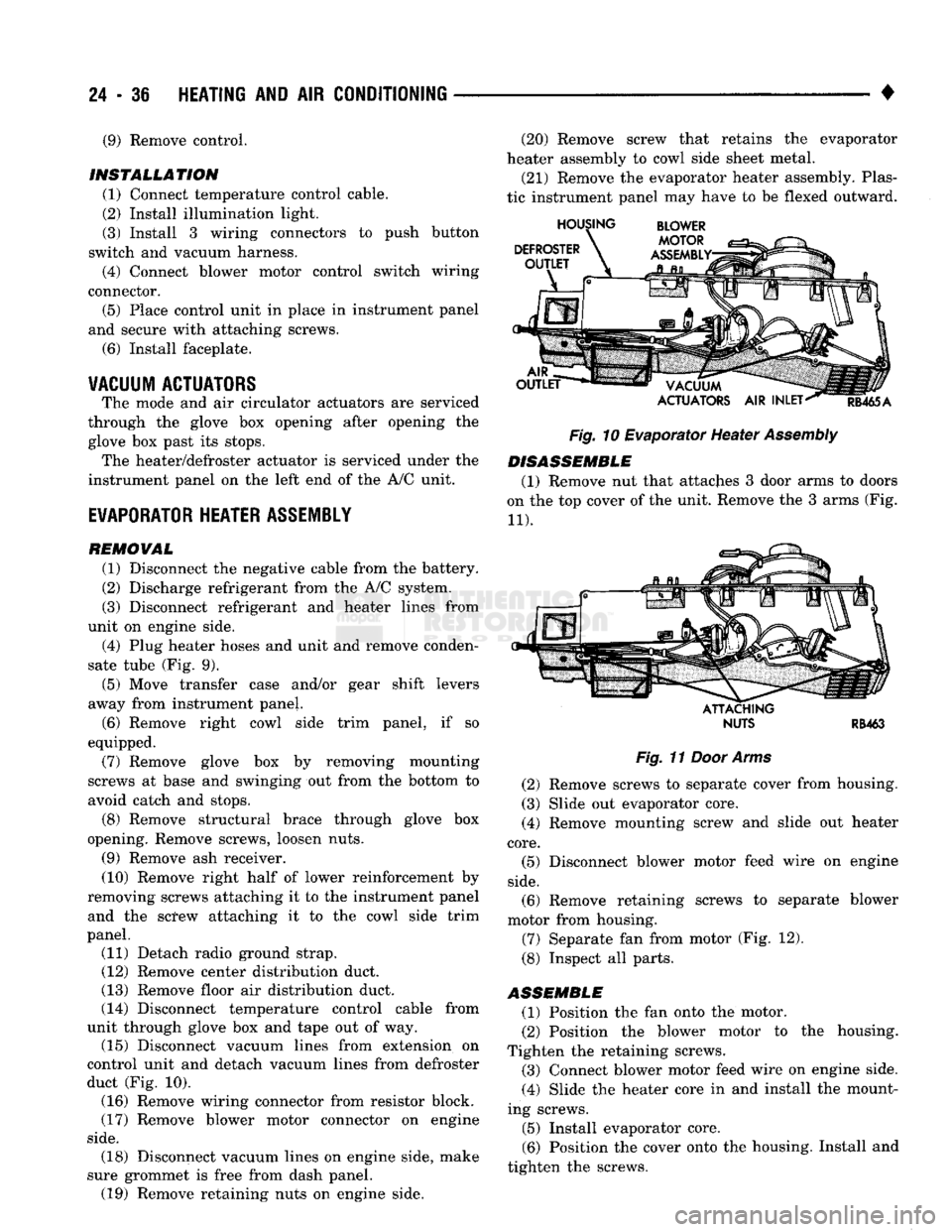
duct (Fig. 10). (16) Remove wiring connector from resistor block.
(17) Remove blower motor connector on engine
side.
(20) Remove screw that retains the evaporator
heater assembly to cowl side sheet metal.
(21) Remove the evaporator heater assembly. Plas
tic instrument panel may have to be flexed outward.
Fig.
10 Evaporator Heater
Assembly
DISASSEMBLE
(1) Remove nut that attaches 3 door arms to doors
on the top cover of the unit. Remove the 3 arms (Fig.
11).
ATTACHING
NUTS
RB463
Fig.
11
Door Arms
(2) Remove screws to separate cover from housing.
(3) Slide out evaporator core. (4) Remove mounting screw and slide out heater
core.
(5) Disconnect blower motor feed wire on engine
side.
(6) Remove retaining screws to separate blower
motor from housing.
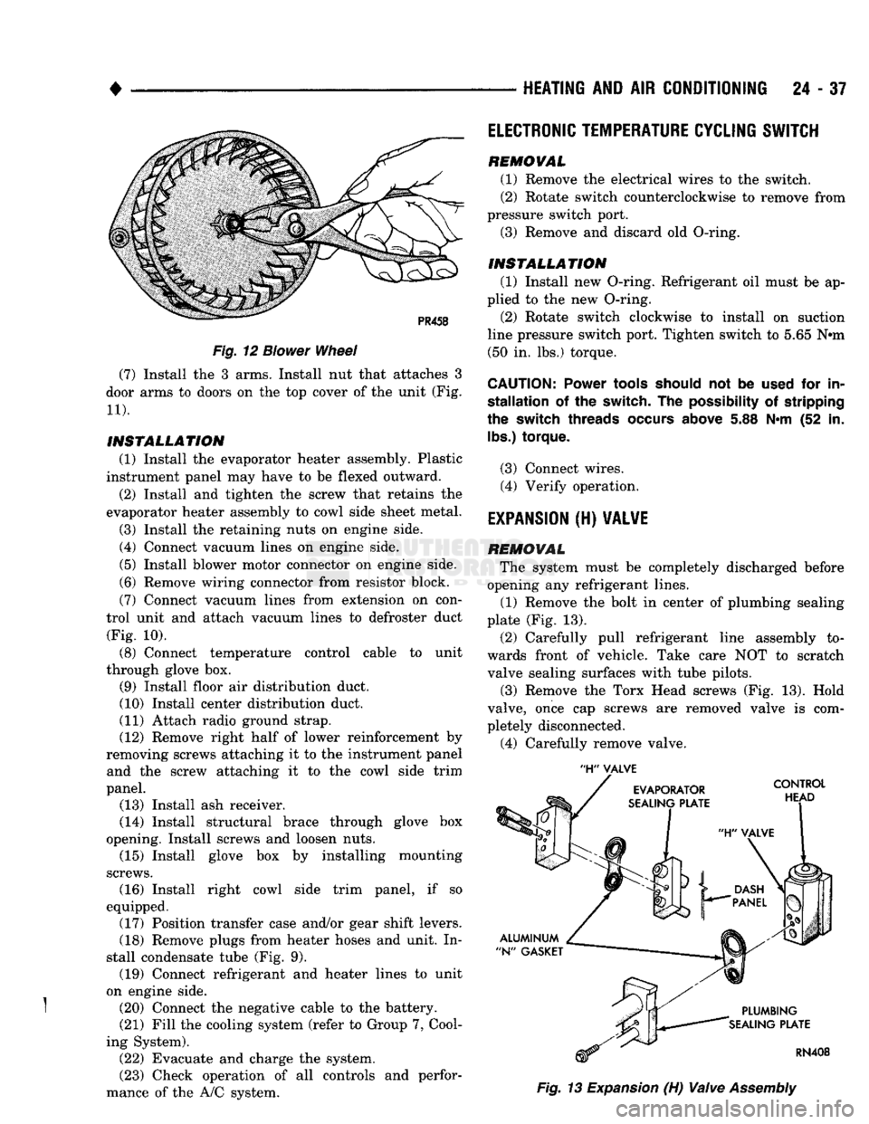
(7) Separate fan from motor (Fig. 12).
(8) Inspect all parts.
ASSEMBLE
(1) Position the fan onto the motor.
(2) Position the blower motor to the housing.
Tighten the retaining screws. (3) Connect blower motor feed wire on engine side.
(4) Slide the heater core in and install the mount
ing screws.
(5) Install evaporator core.
(6) Position the cover onto the housing. Install and
tighten the screws. (18) Disconnect vacuum lines on engine side, make
sure grommet is free from dash panel. (19) Remove retaining nuts on engine side.
Page 1474 of 1502
•
Fig.
12
Blower
Wheel
(7) Install the 3 arms. Install nut that attaches 3
door arms to doors on the top cover of the unit (Fig.
11).
INSTALLATION
(1) Install the evaporator heater assembly. Plastic
instrument panel may have to be flexed outward.
(2) Install and tighten the screw that retains the
evaporator heater assembly to cowl side sheet metal.
(3) Install the retaining nuts on engine side.
(4) Connect vacuum lines on engine side.
(5) Install blower motor connector on engine side.
(6) Remove wiring connector from resistor block.
(7) Connect vacuum lines from extension on con
trol unit and attach vacuum lines to defroster duct (Fig. 10).
(8) Connect temperature control cable to unit
through glove box. (9) Install floor air distribution duct.
(10) Install center distribution duct.
(11) Attach radio ground strap. (12) Remove right half of lower reinforcement by
removing screws attaching it to the instrument panel and the screw attaching it to the cowl side trim
panel. (13) Install ash receiver.
(14) Install structural brace through glove box
opening. Install screws and loosen nuts. (15) Install glove box by installing mounting
screws. (16) Install right cowl side trim panel, if so
equipped. (17) Position transfer case and/or gear shift levers.
(18) Remove plugs from heater hoses and unit. In
stall condensate tube (Fig. 9). (19) Connect refrigerant and heater lines to unit
on engine side.
} (20) Connect the negative cable to the battery. (21) Fill the cooling system (refer to Group 7, Cool
ing System). (22) Evacuate and charge the system.
(23) Check operation of all controls and perfor
mance of the A/C system.
HEATING
AND AIR
CONDITIONING
24 - 37
'H"
VALVE
Fig.
13
Expansion
(H)
Valve
Assembly
ELECTRONIC
TEMPERATURE
CYCLING
SWITCH
REMOVAL
(1) Remove the electrical wires to the switch.
(2) Rotate switch counterclockwise to remove from
pressure switch port. (3) Remove and discard old O-ring.
INSTALLATION
(1) Install new O-ring. Refrigerant oil must be ap
plied to the new O-ring.
(2) Rotate switch clockwise to install on suction
line pressure switch port. Tighten switch to 5.65 N#m (50 in. lbs.) torque.
CAUTION:
Power
tools
should
not be
used
for in
stallation
of the switch. The
possibility
of stripping
the
switch
threads
occurs
above
5.88 N*m (52 in.
lbs.)
torque.
(3) Connect wires. (4) Verify operation.
EXPANSION
(H)
VALVE
REMOVAL
The system must be completely discharged before
opening any refrigerant lines. (1) Remove the bolt in center of plumbing sealing
plate (Fig. 13).
(2) Carefully pull refrigerant line assembly to
wards front of vehicle. Take care NOT to scratch valve sealing surfaces with tube pilots.
(3) Remove the Torx Head screws (Fig. 13). Hold
valve, once cap screws are removed valve is com
pletely disconnected.
(4) Carefully remove valve.
Page 1500 of 1502
COMPONENT AND SYSTEM INDEX
Name
Group-page
AUDIO
SYSTEMS
8F-1
SERVICE
PROCEDURES 8F-7
TEST PROCEDURES 8F-2
BATTERY/STARTER/GENERATOR SERVICE 8B-1 BATTERY SERVICE PROCEDURES 8B-1
GENERATOR SERVICE 8B-6
SPECIFICATIONS 8B-9
STARTER SERVICE PROCEDURES 8B-4
BODY COMPONENTS 23-1 CAB/BODY INTERIOR COMPONENTS
23-35
DOORS
23-21
EXTERIOR COMPONENTS 23-1
FIXED GLASS
23-29
PAINT
CODE CHART
23-54
REFINISHING PROCEDURES
23-54
BRAKES
5-1 BENDIX DISC BRAKE 5-37 BRAKE ADJUSTMENTS-BRAKE BLEEDING 5-7
BRAKE DIAGNOSIS 5-3
CHRYSLER
DISC BRAKE 5-27 DRUM BRAKES—ELEVEN INCH 5-46
DRUM BRAKES-TWELVE INCH 5-50
GENERAL INFORMATION 5-1 MASTER CYLINDER—COMBINATION VALVE-BRAKE
LINES 5-10
PARKING BRAKES 5-56
POWER BRAKE BOOSTER-BRAKE PEDAL 5-20 POWER BRAKE VACUUM PUMP-DIESEL ENGINE. . 5-22
REAR
WHEEL ANTILOCK
(RWAL)
BRAKES 5-59
SPECIFICATIONS 5-65
CHIME/BUZZER WARNING
SYSTEMS
8U-1
CLUTCH 6-1 CLUTCH DIAGNOSIS 6-2 CLUTCH SERVICE 6-11
COOLING SYSTEM 7-1
DIAGNOSIS 7-4
ENGINE ACCESSORY DRIVE BELTS 7-40
ENGINE BLOCK HEATERS 7-48
SERVICE
PROCEDURES 7-15 SPECIFICATIONS 7-49
ELECTRICAL 8A-1 BATTERY TEST PROCEDURES 8A-2
ENGINE STARTER MOTOR TEST PROCEDURES.... 8A-9
GENERAL INFORMATION 8A-1
GENERATOR TEST PROCEDURES ON VEHICLE . . . 8A-13
GROUP INDEX 8A-1
SPECIFICATIONS 8A-18
BATTERY/STARTING/CHARGING
SYSTEMS
DIAGNOSTICS 8A-1
EMISSION
CONTROL
SYSTEMS.
25-1 AIR INJECTION SYSTEM—5.9L HDC-GAS ENGINE . 25-15 COMPONENT REMOVAL/INSTALLATION 25-17 EVAPORATIVE EMISSION CONTROLS 25-6
EXHAUST EMISSION CONTROLS 25-10
GENERAL INFORMATION 25-1
ENGINES 9-1 3.9L ENGINE SERVICE PROCEDURES 9-17 5.2L ENGINE SERVICE PROCEDURES 9-47
5.9L (DIESEL) ENGINE SERVICE PROCEDURES . . . 9-107
Name
Group-page
5.9L ENGINE SERVICE PROCEDURES 9-77 ENGINE DIAGNOSIS 9-5
STANDARD SERVICE PROCEDURES 9-1
EXHAUST SYSTEM AND INTAKE MANIFOLD 11-1
EXHAUST SYSTEM DIAGNOSIS 11-3
GENERAL INFORMATION 11-1
SERVICE
PROCEDURES (DIESEL ENGINES) 11-17
SERVICE
PROCEDURES (GASOLINE ENGINES) 11-4
SPECIFICATIONS 11-27
FRAME AND BUMPERS 13-1 ATTACHED COMPONENTS 13-30
BUMPERS
13-1
FRAME 13-20
SNOW PLOW 13-3
FRONT SUSPENSION AND AXLE 2-1 FRONT SUSPENSION—2WD VEHICLES 2-7
FRONT SUSPENSION—4WD VEHICLES 2-14 FRONT WHEEL ALIGNMENT 2-3
GENERAL INFORMATION 2-1 MODEL 44 FRONT AXLE 2-17
MODEL 60 FRONT AXLE 2-49
TORQUE SPECIFICATIONS 2-75
FUEL SYSTEM 14-1 ACCELERATOR PEDAL AND THROTTLE CABLE . . . 14-25
DIESEL
FUEL INJECTION—COMPONENT DESCRIPTION/SYSTEM OPERATION 14-76
DIESEL
FUEL INJECTION-GENERAL DIAGNOSIS. . 14-88
DIESEL
FUEL INJECTION-SERVICE
PROCEDURES
14-106
FUEL DELIVERY SYSTEM-EXCEPT DIESEL 14-3
FUEL DELIVERY-DIESEL ENGINE 14-15 FUEL TANKS 14-20
GENERAL INFORMATION 14-1 MULTI-PORT FUEL INJECTION (MPI)-COMPONENT DESCRIPTION/SYSTEM OPERATION-EXCEPT
DIESEL
14-29
MULTI-PORT FUEL INJECTION
(MPlj-COMPONENT
REMOVAL/INSTALLATION-EXCEPT DIESEL .... 14-64
MULTI-PORT FUEL INJECTION (MPI)—GENERAL DIAGNOSIS-EXCEPT DIESEL 14-43
SERVICE
ADJUSTMENTS-DIESEL
14-122
SPECIFICATIONS
14-123
HEATING AND AIR CONDITIONING 24-1 CLIMATE CONTROL SYSTEM
24-29
COMPRESSOR
SERVICE
(SD-709)
24-21 DIAGNOSTIC PROCEDURES 24-3
GENERAL INFORMATION 24-1 REFRIGERANT SYSTEM SERVICE PROCEDURES . . 24-17
TORQUE SPECIFICATIONS
24-39
HORNS 8G-1
SERVICE
PROCEDURES 8G-3
TEST PROCEDURES 8G-1
IGNITION
SYSTEMS
8D-1 COMPONENT IDENTIFICATION/SYSTEM OPERATION. 8D-1
COMPONENT REMOVAL/INSTALLATION 8D-18 DIAGNOSTICS/SERVICE PROCEDURES 8D-7
IGNITION
SWITCH
8D-25
SPECIFICATIONS
8D-28
INSTRUMENT PANEL AND GAUGES 8E-1
Page 1501 of 1502
CLUSTER
AND
GAUGE SERVICE PROCEDURES
. . . 8E-12
CLUSTER
AND
GAUGE TEST PROCEDURES
8E-5
GENERAL INFORMATION
8E-1
MESSAGE
CENTER-DIESEL ENGINE
8E-4
MESSAGE
CENTER-GAS ENGINE
8E-3
SWITCH
AND
PANEL COMPONENT SERVICE
8E-16
INTRODUCTION
lntro.-1
DESIGNATIONS, LABELS/PLATES/DECALS, CODES AND DIMENSIONS/WEIGHTS
Intro.-1
MEASUREMENT
AND
TORQUE SPECIFICATIONS
lntro.-11
LAMPS
8L-1
BULB APPLICATION
8L-11
EXTERIOR LAMPS
8L-1
EXTERIOR LAMPS SERVICE PROCEDURES
8L-3
INTERIOR LAMPS
8L-10
LUBRICATION
AND
MAINTENANCE
0-1
CHASSIS
AND
BODY
0-28
DRIVETRAIN
0-22
ENGINE MAINTENANCE
0-14
GENERAL INFORMATION
0-1
POWER DOOR LOCKS
8P-1
SERVICE
PROCEDURES
8P-2
TEST PROCEDURES
8P-1
POWER MIRRORS
8T-1
SERVICE
PROCEDURES
8T-2
TEST PROCEDURES
8T-1
POWER WINDOWS
8S-1
SERVICE
PROCEDURES
8S-3
TEST PROCEDURES
8S-1
PROPELLER SHAFTS
16-1
GENERAL INFORMATION
16-1
PROPELLER SHAFT REPLACEMENT
16-8
SERVICE
DIAGNOSIS/PROCEDURES
16-3
TORQUE SPECIFICATIONS
16-15
UNIVERSAL
JOINT
REPLACEMENT
16-10
REAR
SUSPENSION
AND
AXLE
3-1
8
3/8 and 9 1/4
AXLE
3-11
GENERAL INFORMATION
3-1
MODEL
60 and 70
AXLES
3-29
POWER-LOK DIFFERENTIAL
3-55
REAR
SUSPENSION—2WD
and 4WD
VEHICLES
.... 3-3
SERVICE
DIAGNOSIS
3-6
SPECIFICATIONS
3-27
SURE-GRIP
DIFFERENTIAL SERVICE
3-28
TORQUE SPECIFICATIONS
3-59
TRAC-LOK DIFFERENTIAL
3-51
REAR
WINDOW DEFOGGER
8N-1
REPAIR PROCEDURES (GRID LINES, TERMINALS,
AND PIGTAILS)
8N-3
SERVICE
PROCEDURES
8N-4
TEST PROCEDURES
8N-1
STEERING
19-1
GENERAL INFORMATION
19-1
POWER STEERING PUMP
19-11
POWER STEERING SYSTEM DIAGNOSIS
19-2
RECIRCULATING BALL POWER STEERING GEAR
. . 19-20
STEERING COLUMN
19-35
STEERING LINKAGE
19-17
TORQUE SPECIFICATIONS
19-40
TRANSMISSION
AND
TRANSFER CASE
21-1
AUTOMATIC TRANSMISSION DIAGNOSIS
AND
TESTING
21-85
AUTOMATIC TRANSMISSION REMOVAL
AND
INSTALLATION
21-142
AUTOMATIC TRANSMISSION—32RH/36RH/37RH/
42RH/46RH
21-73
G360
MANUAL TRANSMISSION
21-46
G360
TRANSMISSION OVERHAUL
21-53
GENERAL INFORMATION-32RH/36RH/37RH
21-73
GENERAL INFORMATION—42RH/46RH
. . . 21-78
IN-VEHICLE SERVICE—32RH/36RH/37RH/ 42RH/46RH
21-130
NP205
TRANSFER CASE
21-342
NP241
TRANSFER CASE
21-350
NV4500
MANUAL TRANSMISSION
21-1
NV4500
TRANSMISSION OVERHAUL
21-6
OVERDRIVE
UNIT
OVERHAUL—42RH/46RH
21-324
TRANSMISSION OVERHAUL—32RH
21-152
TRANSMISSION OVERHAUL—36RH/37RH
21-192
TRANSMISSION OVERHAUL—42RH
21-233
TRANSMISSION OVERHAUL—46RH
21-278
TRANSMISSION/TRANSFER CASE SPECIFICATIONS
21-364
TURN SIGNALS
AND
HAZARD WARNING FLASHER
. . . 8J-1
GENERAL INFORMATION
8J-1
MULTIFUNCTION SWITCH SERVICE PROCEDURES.
. 8J-3
MULTIFUNCTION SWITCH TESTING PROCEDURES.
. 8J-2
VEHICLE
SPEED
CONTROL SYSTEM
8H-1
SERVICE
PROCEDURES
8H-11
TEST PROCEDURES
8H-7
WHEELS
AND
TIRES
22-1
TIRES
22-1
TORQUE SPECIFICATIONS
22-13
VEHICLE VIBRATION
22-11
WHEELS
22-6
WINDSHIELD WIPER
AND
WASHER
SYSTEMS
8K-1
INTERMITTENT WINDSHIELD WIPER FUNCTION
AND
SWITCH TESTING PROCEDURES
8K-6
TWO
SPEED
WINDSHIELD WIPER MOTOR
AND
SWITCH TESTING PROCEDURES
8K-1
WINDSHIELD WASHERS
8K-10
WINDSHIELD WIPER SYSTEM SERVICE
PROCEDURES
8K-7
WIRING DIAGRAMS
8W-1
COMPONENT IDENTIFICATION
8W-9
GENERAL INFORMATION
8W-1
SPLICE
LOCATIONS
8W-29
WIRING DIAGRAMS AD-BODY
8W-37