1993 DODGE TRUCK run flat
[x] Cancel search: run flatPage 663 of 1502
CAUTION:
Th© plunger and
tappet
bodies are not
interchangeable. The plunger and valve must al
ways
be
fitted
to the
original
body. It is advisable to
work
on one
tappet
at a
time
to avoid
mixing
of parts. Mixed
parts
are not
compatible.
DO NOT
dis
assemble
a
tappet
on a
dirty
work
bench,
DISASSEMBLE
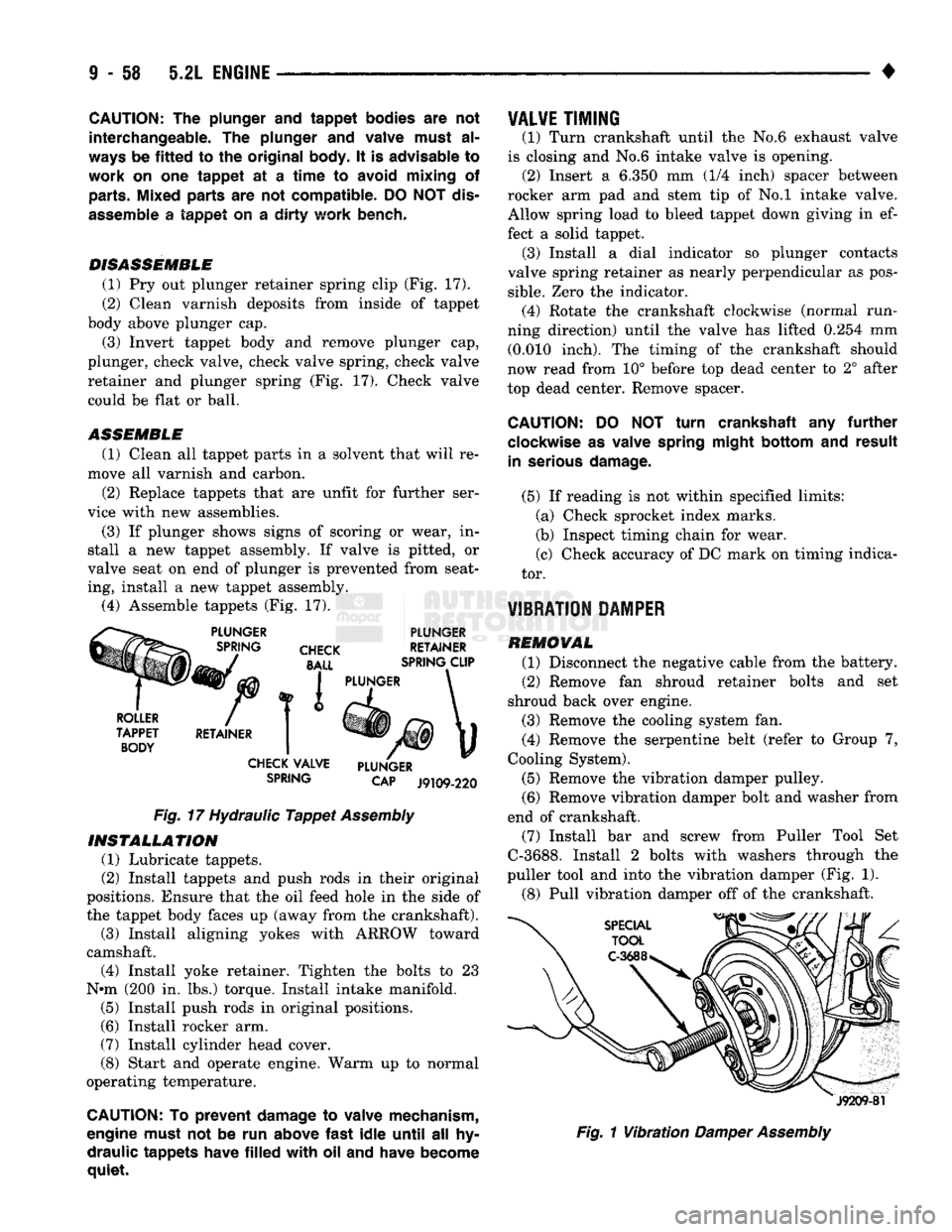
(1) Pry out plunger retainer spring clip (Fig. 17).
(2) Clean varnish deposits from inside of tappet
body above plunger cap.
(3) Invert tappet body and remove plunger cap,
plunger, check valve, check valve spring, check valve
retainer and plunger spring (Fig. 17). Check valve could be flat or ball.
ASSEMBLE
(1) Clean all tappet parts in a solvent that will re
move all varnish and carbon.
(2) Replace tappets that are unfit for further ser
vice with new assemblies.
(3) If plunger shows signs of scoring or wear, in
stall a new tappet assembly. If valve is pitted, or
valve seat on end of plunger is prevented from seat
ing, install a new tappet assembly. (4) Assemble tappets (Fig. 17).
PLUNGER
CHECK
BALL
PLUNGER
RETAINER
SPRING CLIP
ROLLER
TAPPET BODY RETAINER I PLUNGER
CHECK VALVE
SPRING PLUNGER
CAP
J9109-220
Fig.
17 Hydraulic
Tappet
Assembly
INSTALLATION
(1) Lubricate tappets.
(2) Install tappets and push rods in their original
positions. Ensure that the oil feed hole in the side of
the tappet body faces up (away from the crankshaft). (3) Install aligning yokes with ARROW toward
camshaft. (4) Install yoke retainer. Tighten the bolts to 23
N»m (200 in. lbs.) torque. Install intake manifold. (5) Install push rods in original positions.
(6) Install rocker arm.
(7) Install cylinder head cover.
(8) Start and operate engine. Warm up to normal
operating temperature.
CAUTION: To
prevent
damage to valve mechanism,
engine must not be run above
fast
idle
until
all hy
draulic
tappets
have
filled
with
oil and have become
quiet.
VALVE
TIMING
(1) Turn crankshaft until the No.6 exhaust valve
is closing and No.6 intake valve is opening. (2) Insert a 6.350 mm (1/4 inch) spacer between
rocker arm pad and stem tip of No.l intake valve. Allow spring load to bleed tappet down giving in ef
fect a solid tappet. (3) Install a dial indicator so plunger contacts
valve spring retainer as nearly perpendicular as pos
sible.
Zero the indicator. (4) Rotate the crankshaft clockwise (normal run
ning direction) until the valve has lifted 0.254 mm (0.010 inch). The timing of the crankshaft should
now read from 10° before top dead center to 2° after
top dead center. Remove spacer.
CAUTION:
DO NOT
turn
crankshaft any
further
clockwise as valve spring
might
bottom
and
result
in serious
damage.
(5) If reading is not within specified limits: (a) Check sprocket index marks.
(b) Inspect timing chain for wear.
(c) Check accuracy of DC mark on timing indica
tor.
VIBRATION DAMPER
REMOVAL (1) Disconnect the negative cable from the battery.
(2) Remove fan shroud retainer bolts and set
shroud back over engine.
(3) Remove the cooling system fan.
(4) Remove the serpentine belt (refer to Group 7,
Cooling System).
(5) Remove the vibration damper pulley. (6) Remove vibration damper bolt and washer from
end of crankshaft. (7) Install bar and screw from Puller Tool Set
C-3688. Install 2 bolts with washers through the
puller tool and into the vibration damper (Fig. 1).
(8) Pull vibration damper off of the crankshaft.
J9209-81
Fig.
1
Vibration
Damper
Assembly
Page 679 of 1502
ENGINE
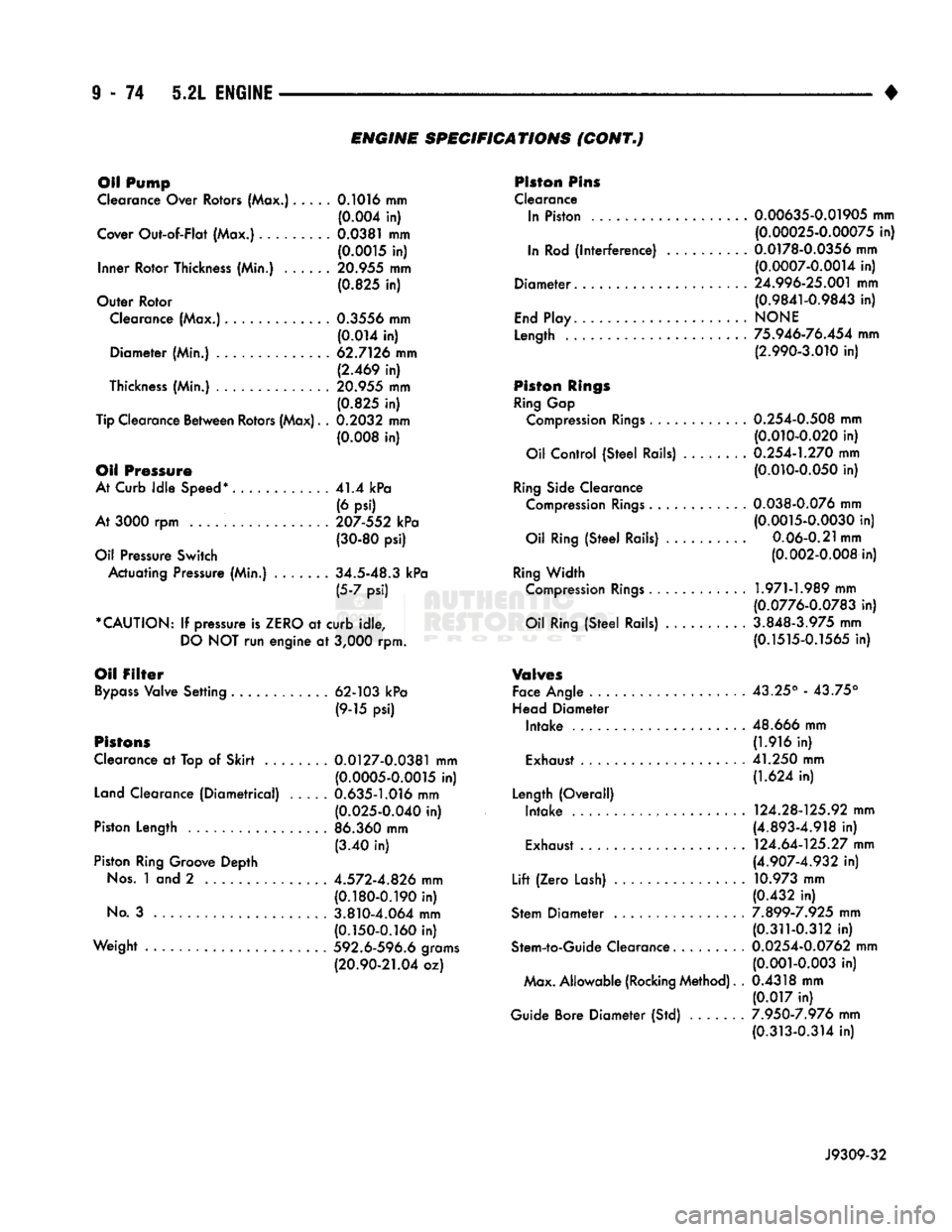
SPECIFICATIONS
(CONT*)
Oil Pump
Clearance Over Rotors (Max.)..... 0.1016 mm (0.004 in)
Cover
Out-of-Flat
(Max.).. ... 0.0381 mm (0.0015 in)
Inner
Rotor
Thickness (Min.) 20.955 mm (0.825 in)
Outer
Rotor
Clearance (Max.)............. 0.3556 mm
(0.014 in)
Diameter
(Min.) 62.7126 mm (2.469 in)
Thickness (Min.) 20.955 mm
(0.825 in)
Tip Clearance
Between
Rotors (Max). . 0.2032 mm
(0.008 in)
Oil Pressure
At Curb
Idle
Speed*
41.4 kPa
(6 psi)
At 3000 rpm 207-552 kPa (30-80 psi)
Oil Pressure
Switch
Actuating
Pressure (Min.) . 34.5-48.3 kPa (5-7 psi)
*CAUTION:
If pressure is
ZERO
at
curb
idle,
DO
NOT run
engine
at 3,000 rpm.
Oil
Filter
Bypass
Valve
Setting
............
62-103 kPa
(9-15 psi)
Pistons
Clearance at Top of
Skirt
.... 0.0127-0.0381 mm (0.0005-0.0015 in)
Land Clearance
(Diametrical)
..... 0.635-1.016 mm (0.025-0.040 in)
Piston
Length
.................
86.360 mm
(3.40 in)
Piston Ring Groove
Depth
Nos.
1 and 2 4.572-4.826 mm (0.180-0.190 in)
No.
3 3.810-4.064 mm (0.150-0.160 in)
Weight
592.6-596.6 grams
(20.90-21.04 oz) Piston Pins
Clearance In Piston . 0.00635-0.01905 mm (0.00025-0.00075 in)
In Rod
(interference)
..........
0.0178-0.0356 mm (0.0007-0.0014 in)
Diameter.
24.996-25.001 mm (0.9841-0.9843 in)
End
Play
NONE
Length
75.946-76.454 mm (2.990-3.010 in)
Piston
Rings
Ring Gap Compression
Rings
. 0.254-0.508 mm (0.010-0.020 in)
Oil
Control
(Steel
Rails) . 0.254-1.270 mm (0.010-0.050 in)
Ring Side Clearance Compression
Rings
0.038-0.076 mm (0.0015-0.0030 in)
Oil Ring
(Steel
Rails)
..........
0.06-0.21 mm (0.002-0.008 in)
Ring
Width
Compression
Rings
1.971-1.989 mm (0.0776-0.0783 in)
Oil Ring
(Steel
Rails) 3.848-3.975 mm (0.1515-0.1565 in)
V®hr©s
Face Angle 43.25° - 43.75°
Head
Diameter
Intake
.....................
48.666 mm (1.916 in)
Exhaust 41.250 mm (1.624 in)
Length
(Overall)
Intake
. 124.28-125.92 mm (4.893-4.918 in)
Exhaust . 124.64-125.27 mm (4.907-4.932 in)
Lift
(Zero
Lash) 10.973 mm (0.432 in)
Stem
Diameter
7.899-7.925 mm (0.311-0.312 in)
Stem-to-Guide
Clearance......... 0.0254-0.0762 mm (0.001-0.003 in)
Max.
Allowable
(Rocking Method). . 0.4318 mm
(0.017 in)
Guide Bore
Diameter
(Std) 7.950-7.976 mm (0.313-0.314 in)
J9309-32
Page 693 of 1502
9
- 88 5.9L
ENGINE
•
CAUTION:
The
plunger
and
tappet
bodies
are not
interchangeable,.
The
plunger
and
valve must
al
ways
be
fitted
to the
original
body,
It is
advisable
to
work
on one
tappet
at a time to
avoid mixing
of
parts. Mixed parts
are not
compatible.
DO
NOT dis
assemble
a
tappet
on a dirty
work bench.
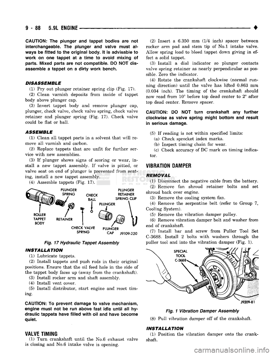
DISASSEMBLE (1) Pry out plunger retainer spring clip (Fig. 17).
(2) Clean varnish deposits from inside of tappet
body above plunger cap.
(3) Invert tappet body and remove plunger cap,
plunger, check valve, check valve spring, check valve
retainer and plunger spring (Fig, 17). Check valve
could be flat or ball.
ASSEMBLE
(1) Clean all tappet parts in a solvent that will re
move all varnish and carbon. (2) Replace tappets that are unfit for further ser
vice with new assemblies.
(3) If plunger shows signs of scoring or wear, in
stall a new tappet assembly. If valve is pitted, or
valve seat on end of plunger is prevented from seat ing, install a new tappet assembly.
(4) Assemble tappets (Fig. 17).
SPiING
CAP J9109-220
Fig.
17 Hydraulic
Tappet
Assembly INSTALLATION
(1) Lubricate tappets.
(2) Install tappets and push rods in their original
positions. Ensure that the oil feed hole In the side of
the tappet body faces up (away from the crankshaft). (3) Install rocker arm and shaft assembly.
(4) Install vent cover.
(5) Install distributor, start engine and reset tim
ing.
CAUTION:
To
prevent damage
to
valve mechanism,
engine must
not be run
above
fast
idle
until
all hy
draulic tappets have
filled
with oil and
have become
quiet.
¥AL¥E
TIMING
(1) Turn crankshaft until the No.6 exhaust valve
is closing and No.6 intake valve Is opening. (2) Insert a 6.350 mm (1/4 inch) spacer between
rocker arm pad and stem tip of No.l intake valve.
Allow spring load to bleed tappet down giving in ef
fect a solid tappet. (3) Install a dial indicator so plunger contacts
valve spring retainer as nearly perpendicular as pos
sible.
Zero the Indicator.
(4) Rotate the crankshaft clockwise (normal run
ning direction) until the valve has lifted 0.863 mm (0.034 inch). The timing of the crankshaft should
now read from 10° before top dead center to 2° after
top dead center. Remove spacer.
CAUTION:
DO NOT
turn crankshaft
any
further
clockwise
as
valve spring might bottom
and
result
in serious damage.
(5) If reading is not within specified limits: (a) Check sprocket index marks.
(b) Inspect timing chain for wear.
(c) Check accuracy of DC mark on timing indica
tor. -
¥IBRATI0N
PAMPER
REMOVAL (1) Disconnect the negative cable from the battery.
(2) Remove fan shroud retainer bolts and set
shroud back over engine. (3) Remove the cooling system fan.
(4) Remove the serpentine belt (refer to Group 7,
Cooling System). (5) Remove the vibration damper pulley. (6) Remove vibration damper bolt and washer from
end of crankshaft. (7) Install bar and screw from Puller Tool Set
C-3688. Install 2 bolts with washers through the
puller tool and into the vibration damper (Fig. 1).
J9209-81
Fig.
1
Vibration
Damper
Assembly
(8) Pull vibration damper off of the crankshaft.
INSTALLATION (1) Position the vibration damper onto the crank
shaft.
Page 709 of 1502
9 - 104 5.9L ENGINE
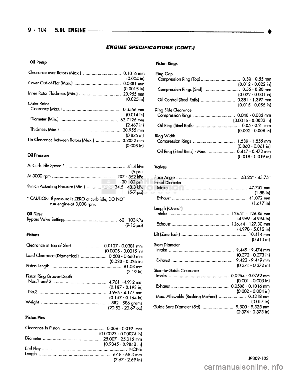
• ENGINE
SPECIFICATIONS
(CONT„)
Oil
Pump
Clearance over Rotors (Max.) 0.1016 mm (0.004 in)
Cover Out-of-Flat (Max.)
0.0381
mm (0.0015 in)
Inner Rotor Thickness (Min.) 20.955 mm
(0.825 in)
Outer Rotor
Clearance (Max.) 0.3556 mm (0.014 in)
Diameter (Min.) 62.7126 mm (2.469 in)
Thickness (Min.) 20.955 mm (0.825 in)
Tip Clearance between Rotors (Max.) 0.2032 mm (0.008 in)
Oil
Pressure
At Curb Idle Speed
*
41.4 kPa (6 psi)
At
3000 rpm 207 - 552 kPa (30 - 80 psi)
Switch Actuating Pressure (Min.) 34.5 - 48.3 kPa (5-7 psi)
* CAUTION: If pressure is ZERO at curb idle, DO NOT run engine at
3,000
rpm.
Oil
Filter
Bypass Valve Setting 62 -103 kPa (9-15 psi)
Pistons
Clearance at
Top
of Skirt 0.0127
-
0.0381
mm (0.0005-0.0015 in)
Land Clearance (Diametrical)
0.508
-
0.660
mm (0.020 -
0.026
in)
Piston Length 81.03 mm (3.19 in)
Piston Ring Groove Depth
Nos.l and 2 4.761 -4.912 mm (0.187-0.193 in)
No.3 3.996-4.177
mm
(0.157-0.164 in)
Weight 582 - 586 grams (20.53 - 20.67 oz)
Piston
Pins
Clearance In Piston
0.006
- 0.019 mm (0.00023 - 0.00074 in)
Diameter 25.007
-
25.015 mm
(0.9845 - 0.9848 in)
End Play NONE
Length 67.8 - 68.3 mm (2.67
-
2.69 in)
Piston
Rings
Ring Gap
Compression Ring (Top) 0.30 - 0.55 mm (0.012-0.022 in)
Compression Rings (2nd) 0.55 - 0.80 mm (0.022 - 0.031 in)
Oil Control (Steel Rails) 0.381 - 1.397 mm (0.015-0.055 in)
Ring Side Clearance Compression Rings
0.040
-
0.085
mm (0.0016-0.0033 in)
Oil Ring (Steel Rails) 0.05 - 0.21 mm (0.002 -
0.008
in)
Ring Width Compression Rings 1.530 - 1.555 mm (0.060 - 0.061 in)
Oil Ring (Steel Rails) - Max
0.447
-
0.473
mm (0.018-0.019 in)
Valves
Face Angle 43.25° - 43.75°
Head Diameter Intake 47.752 mm (1.88 in)
Exhaust 41.072 mm
(1.617 in)
Length (Overall) Intake 126.21 - 126.85 mm
(4.969 - 4.994 in)
Exhaust 126.44 - 127.30 mm
(4.978-5.012 in)
Lift (Zero Lash) 10.414 mm
(0.410 in)
Stem Diameter Intake
9.449
-
9.474
mm
(0.372 -
0.373
in)
Exhaust
9.423
-
9.449
mm
(0.371 -
0.372
in)
Stem-to-Guide Clearance Intake 0.0254 - 0.0762 mm (0.001 -
0.003
in)
Exhaust 0.0508-0.1016 mm
(0.002 -
0.004
in)
Max. Allowable (Rocking Method) 0.4318 mm (0.017 in)
Guide Bore Diameter (Std)
9.500
-
9.525
mm (0.374 -
0.375
in) J9309-103
Page 967 of 1502
19
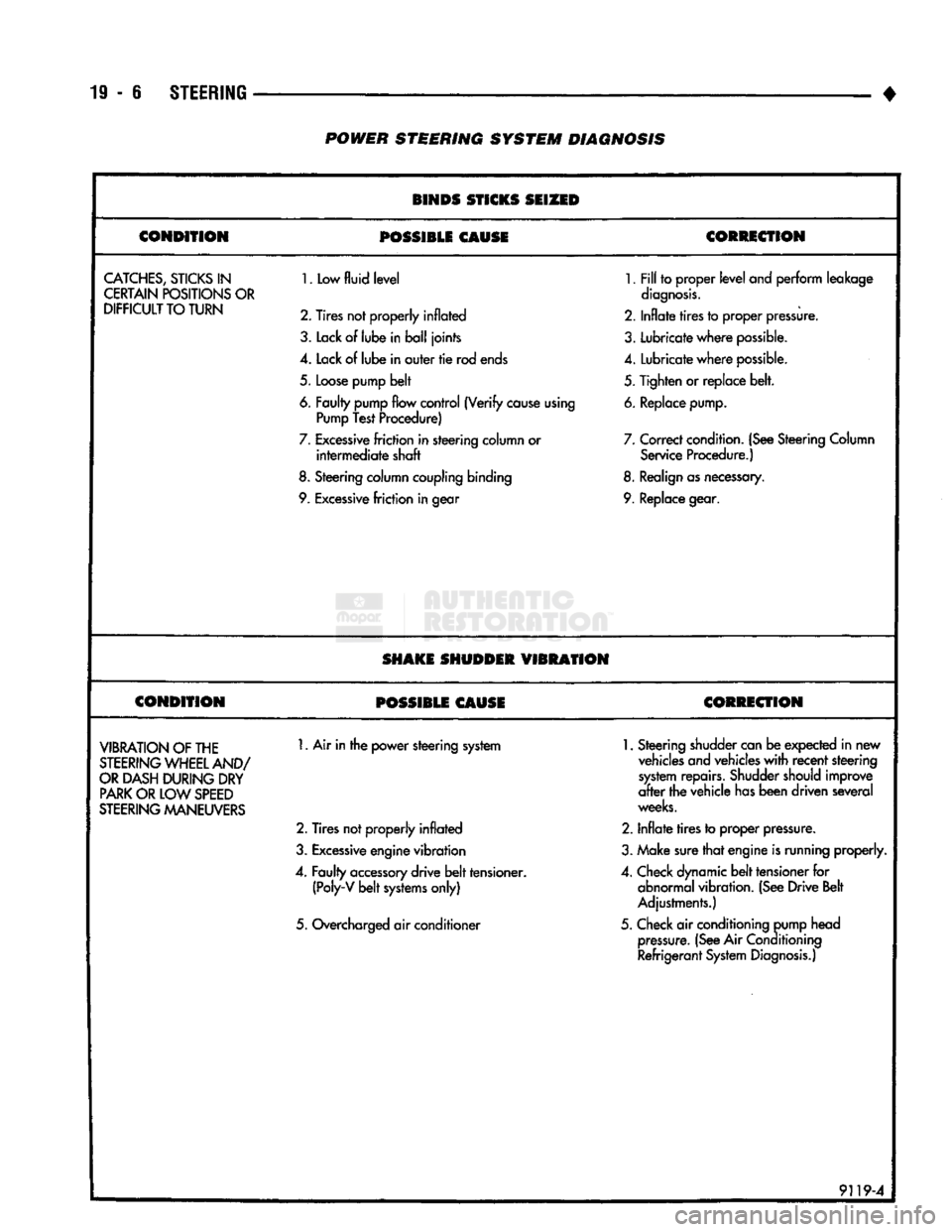
- 6
STEERING
• POWER STEERING SYSTEM DIAGNOSIS
BINDS STICKS SEIZED
CONDITION
POSSIBLE
CAUSE CORRECTION
CATCHES,
STICKS
IN
CERTAIN POSITIONS OR
DIFFICULT
TO TURN
1.
Low
fluid level
2. Tires not properly
inflated
3.
Lack
of
lube
in ball joints
4.
Lack of lube in outer tie rod ends
5.
Loose pump belt
6. Faulty pump flow control (Verify cause using Pump Test Procedure)
7.
Excessive friction in steering column or intermediate shaft
8.
Steering column coupling binding
9. Excessive friction in gear
1.
Fill to proper level
and
perform leakage
diagnosis.
2.
Inflate tires to proper pressure.
3.
Lubricate where possible.
4.
Lubricate where possible.
5.
Tighten or replace belt.
6. Replace pump.
7.
Correct condition. (See Steering Column Service Procedure.)
8. Realign as necessary.
9. Replace gear.
SHAKE SHUDDER
VIBRATION
CONDITION
POSSIBLE CAUSE CORRECTION
VIBRATION
OF THE
STEERING
WHEEL AND/
OR
DASH DURING DRY
PARK
OR LOW
SPEED
STEERING
MANEUVERS
1.
Air in the power steering system
2.
Tires not properly inflated
3.
Excessive engine vibration
4.
Faulty accessory drive belt tensioner. (Poly-V belt systems only)
5.
Overcharged air conditioner
1.
Steering shudder can be expected in new
vehicles and vehicles with recent steering system repairs. Shudder should improve
after the vehicle has been driven several
weeks.
2.
Inflate tires to proper pressure.
3.
Make sure that engine is running properly.
4.
Check dynamic belt tensioner for abnormal vibration. (See Drive Belt
Adjustments.)
5.
Check air conditioning pump head pressure. (See Air
Conditioning
Refrigerant System Diagnosis.)
9119-4
Page 1024 of 1502
NV4500
TRANSMISSION OVERHAUL
21 - 23
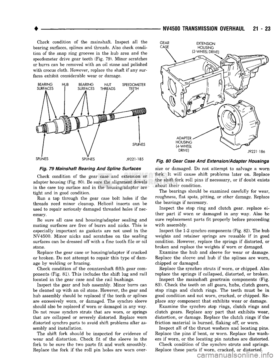
Check condition of the mainshaft. Inspect all the
bearing surfaces, splines and threads. Also check condi tion of the snap ring grooves in the hub area and the speedometer drive gear teeth (Fig. 79). Minor scratches
or burrs can be removed with an oil stone and polished
with crocus cloth. However, replace the shaft if any sur faces exhibit considerable wear or damage.
GEAR
CASE
BEARING
SURFACES HUB
BEARING
NUT
SURFACES THREADS SPEEDOMETER
TEETH
SPLINES SPLINES SPLINES
J922M85
Fig.
79 Mainshaft Bearing And
Spline
Surfaces
Check condition of the gear case and extension or
adapter housing (Fig. 80). Be sure the alignment dowels
in the case top surface and in the housing/adapter are
tight and in good condition.
Run a tap through the gear case bolt holes if the
threads need minor cleanup. Helicoil inserts can be used to repair seriously damaged threaded holes if nec
essary.
Be sure all case and housing/adapter sealing and
mating surfaces are free of burrs and nicks. This is especially important as gaskets are not used in the
NV4500. Minor nicks and scratches on the sealing surfaces can be dressed off with a fine tooth file or oil
stone.
Replace the gear case or housing/adapter if cracked
or broken. Do not attempt to repair this type of dam age by welding or brazing.
Check condition of the countershaft fifth gear com
ponents (Fig. 81). This includes the shift lug and rail located in the gear case and the rail bushings.
Inspect the gear and hub assembly. Minor burrs can
be cleaned up with an oil stone. However, the gear and hub assembly should be replaced if the teeth or splines are excessively worn, or damaged. The synchro sleeve
should also be replaced if worn or damaged in any way.
Do not reuse synchro struts that are worn, or springs
that are collapsed or severely distorted. Replace worn distorted synchro parts to avoid shift problems after as
sembly and installation.
The shift fork should be inspected for evidence of
wear and distortion. Check fit of the sleeve in the
fork to be sure the two parts fit and work smoothly.
Replace the fork if the roll pin holes are worn over-
EXTENSION
HOUSING
(2-WHEEL
DRIVE)
ADAPTER
HOUSING
(4-WHEEL
DRIVE)
J9221-186
Fig.
80 Gear
Case
And Extension/Adapter
Housings
size or damaged. Do not attempt to salvage a worn
fork. It will cause shift problems later on. Replace
the shift fork roll pins if necessary, or if doubt exists about their condition.
The bearings should be examined carefully for wear,
roughness, flat spots, pitting, or other damage. Replace
the bearings if necessary.
Inspect the stop ring and clutch gear, replace ei
ther part if worn or damaged in any way. Also be sure replacement parts fit properly before proceeding
with assembly.
Inspect the 1-2 synchro components (Fig. 82). The hub
weights and retainer springs are reusable if in good condition. However, replace the springs if distorted, or
broken and replace the weights if worn or damaged. Examine the hub and sleeve for wear or damage.
Replace the sleeve and hub if the splines are worn,
chipped or damaged. Replace the synchro struts if worn, or chipped. Also
replace the springs if collapsed, distorted, or broken. Inspect the mainshaft geartrain components (Fig.
83).
Check the teeth on all gears, hubs, clutch gears,
stop rings and clutch rings. The teeth must be in
good condition and not worn, cracked, or chipped. Re
place any component that exhibits wear or damage. Examine the synchro stop rings, clutch rings and
clutch gears. Replace any part that exhibits wear,
distortion, or damage. Replace the clutch rings if the
friction material is burned, flaking off, or worn. Inspect all of the thrust washers and locating pins.
Replace the pins if bent, or worn. Replace the wash ers if worn, or the locating pin notches are distorted. Check condition of the synchro struts and springs.
Replace these parts if worn, cracked, or distorted.
Page 1082 of 1502
•
AUTOMATIC
TRANSMISSION—32RH/36RH/37RH/42RH/46RH
21 - 81
TORQUE
CONVERTER
A three element torque converter
is
used
for all ap
plications.
The
converter consists
of the
impeller,
sta-
tor
and
turbine.
The
converter also contains
an
overrunning clutch
and a
modulated converter clutch
mechanism.
The converter used with
1993,
42RH transmissions
is
new. The
converter
hub was
changed
to
accept
the
new style drive flats
on the oil
pump inner gear.
The
new style converter
is not
interchangeable with pre
vious designs.
The converter modulated clutch consists
of a
slid
ing clutch piston, clutch springs
and the
clutch disc
friction material.
The
clutch provides optimum
torque transfer
and
economy when engaged.
The clutch disc
is
attached
to the
converter front
cover.
The
clutch piston
and
clutch springs
are at
tached
to the
turbine
hub. The
springs dampen
en
gine firing impulses
and
loads during
the
initial
phase
of
converter clutch engagement.
Clutch engagement
is
controlled
by the
converter
clutch valve
and
solenoid. Both
are
located
on the
transmission valve body. Clutch engagement occurs in drive range
at
speeds above approximately 30-35
mph.
The clutch provides reduced engine speed
and
greater fuel economy when engaged. Clutch engage
ment also provides reduced transmission fluid tem
peratures.
COMPONENTS
UNIQUE
TO
DIESEL VERSION
OF
46RH
Planetary
Gears
The transmission
and
overdrive planetary gear car
riers
in the
diesel version
of the
46RH
are
heavy duty components.
The
transmission planetary carriers have four pinion gears.
The
carrier
in the
over
drive compounder
has
five pinion gears.
The
heavy
duty planetary units
are
unique
to the
diesel 46RH.
Clutch
Packs
Clutch packs used
in the
diesel version
of the
46RH contain
the
following number
of
discs
and
plates:
• transmission front/rear clutch
has 4
discs
and 5
steel plates
• overdrive clutch
has 5
discs
and 6
steel plates
• overdrive direct clutch
has 8
discs
and 9
steel
plates
Governor
Weight
Assembly
The governor weight assembly
in the
diesel 46RH
is made
of
alloyed brass.
The
diesel weight assembly
is easily identified
by the
distinctive gold color
of the
alloyed material.
The
heavier weight assembly pro
vides
the
shift points needed
to
offset lower operating speeds
of a
diesel engine. The alloyed weight assembly
is
unique
to the
diesel
46RH.
It is not
interchangeable with
the
weight
as
semblies used
in gas
engine versions.
Diesel
Thermo
Switch
Fourth gear operation
in the
diesel 46RH
is
also
controlled
by two
temperature sensitive thermo- switches.
The first thermo-switch
is the
engine coolant tem
perature switch. This switch prevents overdrive fourth gear operation when engine coolant tempera
ture
is
below approximately
65° F.
The second thermo-switch directly monitors trans
mission fluid temperature.
The
switch will either
downshift
the
transmission
to
third gear,
or
prevent a
3-4
upshift when fluid temperature exceeds
270-275°
F.
The fluid temperature switch
is
located
in a
boss
built into
the
cooler outlet line.
The
boss
and
switch are located approximately
2-3
inches from
the
outlet
line fitting
in the
transmission case.
The engine coolant
and
fluid temperature switches
are
in
circuit with
the
overdrive control switch
in the
instrument panel.
GEAR RATIOS
42RH forward gear ratios
are:
First gear
=
2.74:1
Second gear
= 1.54:1
Third gear
= 1.00:1
Fourth gear
=
0.69:1.
46RH forward gear ratios
are:
First gear
=
2.45:1 Second gear
= 1.45:1
Third gear
= 1.00:1
Fourth gear
=
0.69:1.
RECOMMENDED
FLUID
The recommended
and
preferred fluid
for
42RH/
46RH transmissions
is
Mopar
ATF
Plus, type
7176.
Use Mopar Dexron
II
only when
ATF
Plus
is not
readily available.
TRANSMISSION
IDENTIFICATION
The transmission part
and
identification numbers
and codes
are
stamped
on the
left side
of the
case
just above
the oil pan
gasket surface
(Fig. 3).
The first letter/number group
is the
assembly part
number.
The
next number group
the
transmission
build date.
The
last number group
is the
transmis sion serial number. Refer
to
this information when
ordering replacement parts.
FOURTH
GEAR OVERDRIVE COMPONENTS
42RH/46RH models have three transmission shafts.
An intermediate shaft
is
positioned between
the in
put
and
output shafts.
The
output shaft
is in the
Page 1373 of 1502
22 - 4
WHEELS
AND
TIRES
• puncture is in the tread area (Fig. 7). If outside the
tread area the tire should be replaced.
J8922-6
Fig.
7
Tire
Repair Area
Deflate tire completely before dismounting tire
from the wheel. Use lubrication such as a mild soap solution when dismounting or mounting tire. Use
tools free of burrs or sharp edges.
Before mounting tire on wheel, make sure all rust
scale is removed from the rim. Repaint or seal if nec
essary.
TIRE NOISE
OR
VIBRATION
The radial-ply tire on your vehicle is more sensi
tive to improper mounting, or imbalance. To determine if tires are the cause of vibration,
drive the vehicle over a smooth road at different speeds. Note the effect of acceleration and decelera
tion on noise level. Differential and exhaust noise
will change in intensity as speed varies. Tire noise
will usually remain constant.
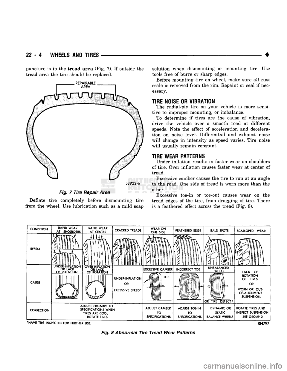
TIRE WEAR PATTERNS
Under inflation results in faster wear on shoulders
of tire. Over inflation causes faster wear at center of
tread. Excessive camber causes the tire to run at an angle
to the road. One side of tread is worn more than the other. Excessive toe-in or toe-out causes wear on the
tread edges of the tire, from dragging of tire. There is a feathered effect across the tread (Fig. 8).
CRACKED
TREADS
WEAR
ON
ONE SIDE FEATHERED EDGE
BALD
SPOTS
IP
fa
SCALLOPED
WEAR
EXCESSIVE
CAMBER INCORRECT
TOE
EXCESSIVE
SPEED*
UNBALANCED
WHEEL LACK
OF
ROTATION
OF TIRES
OR
WORN
OR OUT-
OF-ALIGNMENT
SUSPENSION.
OR
TIRE
DEFECT* ADJUST
PRESSURE
TO
SPECIFICATIONS
WHEN
TIRES ARE COOL
ROTATE
TIRES ADJUST CAMBER
TO
SPECIFICATIONS ADJUST
TOE-IN
TO
SPECIFICATIONS DYNAMIC
OR
STATIC
BALANCE
WHEELS
ROTATE
TIRES
AND
INSPECT SUSPENSION
SEE
GROUP
2
•HAVE
TIRE
INSPECTED
FOR
FURTHER
USE.
RN797
Fig.
8 Abnormal Tire Tread Wear Patterns