1993 CHEVROLET PLYMOUTH ACCLAIM coolant temperature
[x] Cancel search: coolant temperaturePage 1772 of 2438
TACHOMETERÐPCM OUTPUT
The PCM supplies engine RPM to the instrument
panel tachometer. Refer to Group 8 for tachometer
information.
MODES OF OPERATION
As input signals to the PCM change, the PCM
adjusts its response to the output devices. For example,
the PCM must calculate a different injector pulse
width and ignition timing for idle than it does for wide
open throttle (WOT). There are several different modes
of operation that determine how the PCM responds to
the various input signals. There are two different areas of operation, OPEN
LOOP and CLOSED LOOP. During OPEN LOOP modes, the PCM receives input
signals and responds according to preset PCM pro-
gramming. Input from the oxygen (O
2) sensor is not
monitored during OPEN LOOP modes. During CLOSED LOOP modes, the PCM does moni-
tor the oxygen (O
2) sensor input. This input tells the
PCM if the calculated injector pulse width results in an
air-fuel ratio of 14.7 to 1. By monitoring the exhaust
oxygen content, the can PCM fine tune injector pulse
width for optimum fuel economy and low emissions. The single point fuel injection system has the follow-
ing modes of operation:
² Ignition switch ON - Zero RPM
² Engine start-up
² Engine warm-up
² Cruise (Idle)
² Acceleration
² Deceleration
² Wide Open Throttle
² Ignition switch OFF
The engine start-up (cranking), engine warm-up, and
wide open throttle modes are OPEN LOOP modes. The
acceleration, deceleration, and cruise modes, with the
engine at operating temperature are CLOSED
LOOP modes (under most operating conditions).
IGNITION SWITCH ON (ZERO RPM) MODE
When the single point fuel injection system is acti-
vated by the ignition switch, the following actions
occur:
² The PCM determines atmospheric air pressure from
the MAP sensor input to calculate basic fuel strategy.
² The PCM monitors the coolant temperature sensor
and throttle position sensor inputs. The PCM modifies
fuel strategy based on these inputs. When the key is in the ON position and the engine is
not running, the (ASD) and fuel pump relays are not
energized. Therefore, battery voltage is not supplied to
the fuel pump, ignition coil, fuel injector or oxygen
sensor heating element. ENGINE START-UP MODE
This is an OPEN LOOP mode. The following actions
occur when the starter motor is engaged. If the PCM receives a distributor signal it energizes
the auto shutdown (ASD) relay and fuel pump relay to
supply battery voltage to the fuel injector, ignition coil
and oxygen sensor heating element. If the PCM does
not receive a distributor input, it de-energizes the ASD
and fuel pump relays after approximately one second. When the engine idles within 664 RPM of the target
RPM, the PCM compares the current MAP value with
the atmospheric pressure value it received during the
Ignition Switch On (Zero RPM) Mode. If a minimum
difference between the two is not detected, a MAP
sensor fault is set into memory. Once the ASD relay and fuel pump relay have ener-
gized, the PCM:
² Supplies a ground path to the injector. The injector
is pulsed four times per engine revolution instead of
the normal two pulses per revolution.
² Determines injector pulse width based on coolant
temperature, MAP sensor input, throttle position, and
the number of engine revolutions since cranking was
initiated.
² Monitors the coolant temperature sensor, distribu-
tor pick-up, MAP sensor, and throttle position sensor to
determine correct ignition timing.
ENGINE WARM-UP MODE
This is a OPEN LOOP mode. The following inputs
are received by the PCM:
² coolant temperature
² manifold absolute pressure (MAP)
² engine speed (distributor pick-up)
² throttle position
² A/C switch
² battery voltage
The PCM provides a ground path for the injector to
precisely control injector pulse width (by switching the
ground on and off) and fires the injector twice per
engine revolution. The PCM regulates ignition timing.
It also adjusts engine idle speed through the idle air
control motor.
CRUISE OR IDLE MODE
When the engine is at operating temperature this is
a CLOSED LOOP mode. During cruising speed and at
idle the following inputs are received by the PCM:
² coolant temperature
² manifold absolute pressure
² engine speed
² throttle position
² exhaust gas oxygen content
² A/C control positions
² battery voltage
14 - 32 FUEL SYSTEMS Ä
Page 1773 of 2438
The PCM provides a ground path for the injector to
precisely control injector pulse width and fires the in-
jector twice per engine revolution. The PCM controls
engine idle speed and ignition timing. The PCM con-
trols the air/fuel ratio according to the oxygen con-
tent in the exhaust gas.
ACCELERATION MODE This is a CLOSED LOOP mode. The PCM recog-
nizes an abrupt increase in throttle position or MAP
pressure as a demand for increased engine output
and vehicle acceleration. The PCM increases injector
pulse width in response to increased fuel demand.
DECELERATION MODE This is a CLOSED LOOP mode. During decelera-
tion the following inputs are received by the PCM:
² coolant temperature
² manifold absolute pressure
² engine speed
² throttle position
² exhaust gas oxygen content
² A/C control positions
² battery voltage
The PCM may receive a closed throttle input from
the throttle position sensor (TPS) at the same time it
senses an abrupt decrease in manifold pressure from
the manifold absolute pressure (MAP) sensor. This
indicates a hard deceleration. The PCM may reduce
injector firing to once per engine revolution. This
helps maintain better control of the air-fuel mixture
(as sensed through the O
2sensor).
During a deceleration condition, the PCM grounds
the exhaust gas recirculation transducer (EET) sole-
noid. EGR stops when the PCM grounds the solenoid.
WIDE OPEN THROTTLE MODE This is an OPEN LOOP mode. During wide open
throttle operation, the following inputs are received
by the PCM:
² coolant temperature
² manifold absolute pressure
² engine speed
² throttle position
When the PCM senses a wide open throttle condi-
tion through the throttle position sensor (TPS) it
will:
² De-energize the air conditioning relay. This dis-
ables the air conditioning system.
² Provide a ground path for the electric EGR trans-
ducer (EET) solenoid, preventing the EGR system
from functioning. The exhaust gas oxygen content input is not ac-
cepted by the PCM during wide open throttle opera- tion. The PCM will adjust injector pulse width to
supply a predetermined amount of additional fuel.
IGNITION SWITCH OFF MODE
When the ignition switch is turned to the OFF po-
sition, the following occurs:
² All outputs are turned off.
² No inputs are monitored.
² The PCM shuts down.
FUEL PRESSURE REGULATOR
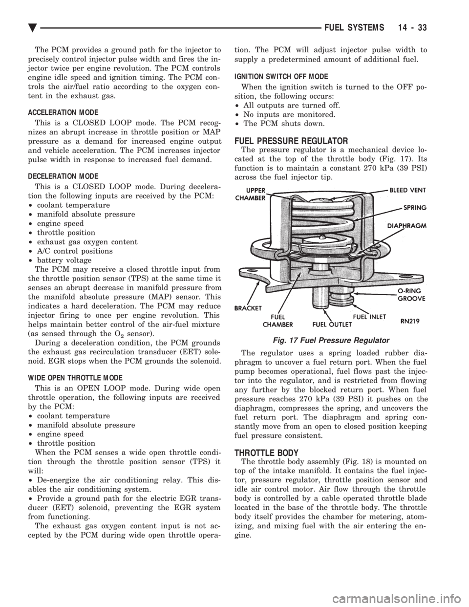
The pressure regulator is a mechanical device lo-
cated at the top of the throttle body (Fig. 17). Its
function is to maintain a constant 270 kPa (39 PSI)
across the fuel injector tip.
The regulator uses a spring loaded rubber dia-
phragm to uncover a fuel return port. When the fuel
pump becomes operational, fuel flows past the injec-
tor into the regulator, and is restricted from flowing
any further by the blocked return port. When fuel
pressure reaches 270 kPa (39 PSI) it pushes on the
diaphragm, compresses the spring, and uncovers the
fuel return port. The diaphragm and spring con-
stantly move from an open to closed position keeping
fuel pressure consistent.
THROTTLE BODY
The throttle body assembly (Fig. 18) is mounted on
top of the intake manifold. It contains the fuel injec-
tor, pressure regulator, throttle position sensor and
idle air control motor. Air flow through the throttle
body is controlled by a cable operated throttle blade
located in the base of the throttle body. The throttle
body itself provides the chamber for metering, atom-
izing, and mixing fuel with the air entering the en-
gine.
Fig. 17 Fuel Pressure Regulator
Ä FUEL SYSTEMS 14 - 33
Page 1777 of 2438
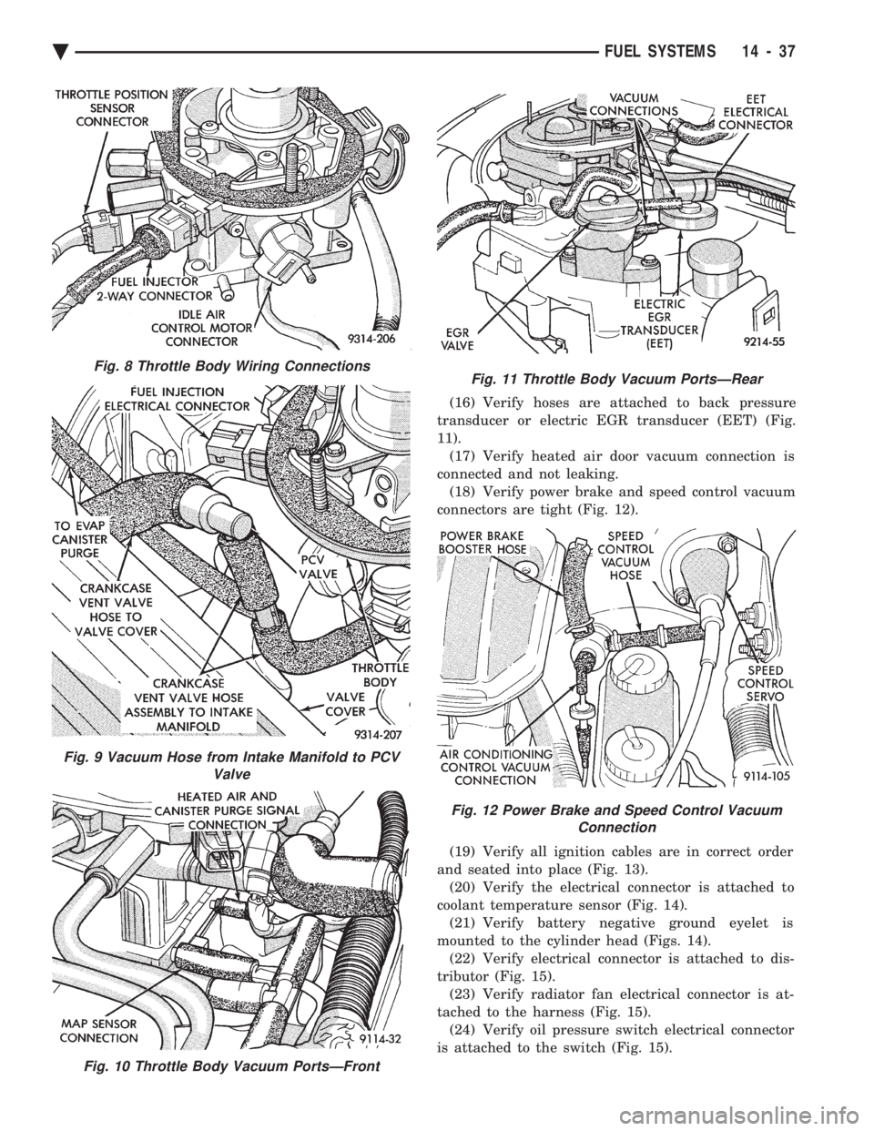
(16) Verify hoses are attached to back pressure
transducer or electric EGR transducer (EET) (Fig.
11). (17) Verify heated air door vacuum connection is
connected and not leaking. (18) Verify power brake and speed control vacuum
connectors are tight (Fig. 12).
(19) Verify all ignition cables are in correct order
and seated into place (Fig. 13). (20) Verify the electrical connector is attached to
coolant temperature sensor (Fig. 14). (21) Verify battery negative ground eyelet is
mounted to the cylinder head (Figs. 14). (22) Verify electrical connector is attached to dis-
tributor (Fig. 15). (23) Verify radiator fan electrical connector is at-
tached to the harness (Fig. 15). (24) Verify oil pressure switch electrical connector
is attached to the switch (Fig. 15).
Fig. 9 Vacuum Hose from Intake Manifold to PCV Valve
Fig. 10 Throttle Body Vacuum PortsÐFront
Fig. 8 Throttle Body Wiring ConnectionsFig. 11 Throttle Body Vacuum PortsÐRear
Fig. 12 Power Brake and Speed Control VacuumConnection
Ä FUEL SYSTEMS 14 - 37
Page 1778 of 2438
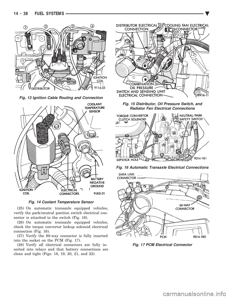
(25) On automatic transaxle equipped vehicles,
verify the park/neutral position switch electrical con-
nector is attached to the switch (Fig. 16). (26) On automatic transaxle equipped vehicles,
check the torque convertor lockup solenoid electrical
connection (Fig. 16). (27) Verify the 60-way connector is fully inserted
into the socket on the PCM (Fig. 17). (28) Verify all electrical connectors are fully in-
serted into relays and that battery connections are
clean and tight (Figs. 18, 19, 20, 21, and 22).
Fig. 13 Ignition Cable Routing and Connection
Fig. 14 Coolant Temperature Sensor
Fig. 15 Distributor, Oil Pressure Switch, and Radiator Fan Electrical Connections
Fig. 16 Automatic Transaxle Electrical Connections
Fig. 17 PCM Electrical Connector
14 - 38 FUEL SYSTEMS Ä
Page 1785 of 2438
SYSTEMS TEST
WARNING: APPLY PARKING BRAKE AND/OR
BLOCK WHEELS BEFORE PERFORMING A TEST
WITH THE ENGINE OPERATING.
OBTAINING DIAGNOSTIC TROUBLE CODES
(1) Connect DRBII scan tool to the data link con-
nector located in the engine compartment near the
powertrain control module (PCM). (2) Start the engine if possible, cycle the transaxle
selector and the A/Cswitch if applicable. Shut off
the engine. (3) Turn the ignition switch on, access Read Fault
Screen. Record all the fault messages shown on the
DRBII scan tool. Observe the malfunction indicator
lamp (check engine lamp on the instrument panel).
The lamp should light for 3 seconds then go out (bulb
check).
STATE DISPLAY TEST MODE
The switch inputs used by the powertrain control
module (PCM) have only two recognized states,
HIGH and LOW. For this reason, the PCM cannot
recognize the difference between a selected switch po-
sition versus an open circuit, a short circuit, or a de-
fective switch. If the change is displayed, it can be
assumed that the entire switch circuit to the PCM is
functional. From the state display screen access ei-
ther State Display Inputs and Outputs or State Dis-
play Sensors.
STATE DISPLAY INPUTS AND OUTPUTS
Connect the DRBII scan tool to the vehicle and ac-
cess the State Display screen. Then access Inputs and
Outputs. The following is a list of the engine control
system functions accessible through the Inputs and
Outputs screen. Park/Neutral Switch (automatic transaxle only)
Speed Control Resume
Brake Switch
Speed Control On/Off
Speed Control Set
A/C Switch Sense
S/C (Speed Control) Vent Solenoid
S/C (Speed Control) Vacuum Solenoid
Torque Converter Clutch Solenoid (3 speed auto-
matic transaxle)
A/C Clutch Relay
EGR Solenoid
Auto Shutdown Relay
Radiator Fan Relay
Purge Solenoid
Malfunction Indicator (Check Engine) Lamp
STATE DISPLAY SENSORS
Connect the DRBII scan tool to the vehicle and ac-
cess the State Display screen. Then access Sensor
Display. The following is a list of the engine control
system functions accessible through the Sensor Dis-
play screen. Oxygen Sensor Signal
Coolant Temperature
Coolant Temp Sensor
Throttle Position
Minimum Throttle
Battery Voltage
MAP Sensor Reading
Idle Air Control Motor Position
Added Adaptive Fuel
Adaptive Fuel Factor
Barometric Pressure
Min Airflow Idl Spd
Engine Speed
Fault #1 Key-On Info
Module Spark Advance
Speed Control Target
Fault #2 Key-On Info
Fault #3 Key-On Info
Speed Control Status
Charging System Goal
Theft Alarm Status
Speed Control Switch Voltage
Map Sensor Voltage
Vehicle Speed
Oxygen Sensor State
MAP Gauge Reading
Throttle Opening (percentage)
Total Spark Advance
CIRCUIT ACTUATION TEST MODE
The circuit actuation test mode checks for proper
operation of output circuits or devices which the pow-
ertrain control module (PCM) cannot internally rec-
ognize. The PCM can attempt to activate these
outputs and allow an observer to verify proper oper-
ation. Most of the tests provide an audible or visual
indication of device operation (click of relay contacts,
spray fuel, etc.). With the exception of an intermit-
tent condition, if a device functions properly during
its test, it can be assumed that the device, its associ-
ated wiring, and its driver circuit are in working or-
der.
OBTAINING CIRCUIT ACTUATION TEST
Connect the DRBII scan tool to the vehicle and ac-
cess the Actuators screen. The following is a list of
the engine control system functions accessible
through Actuators screens. Stop All Tests
Ignition Coil #1
Fuel Injector #1
Idle Air Control Motor Open/Close
Ä FUEL SYSTEMS 14 - 45
Page 1786 of 2438
Radiator Fan Relay
A/C Clutch Relay
Auto Shutdown Relay
Purge Solenoid
S/C Servo Solenoids
Generator Field
Tachometer Output
Torque Converter Clutch Solenoid (3 speed auto-
matic transaxle only)
EGR Solenoid
All Solenoids/Relays
ASD Fuel System Test
Speed Control Vacuum Solenoid
Speed Control Vent Solenoid
THROTTLE BODY MINIMUM AIR FLOW CHECK
PROCEDURE
(1) Connect DRBII scan tool.
(2) Remove air cleaner assembly. Plug the heated
air door vacuum hose. (3) Warm engine in Park or Neutral until the cool-
ing fan has cycled on and off at least once. (4) Hook-up timing check device and tachometer.
(5) Disconnect the coolant temperature sensor and
set basic timing to 12ÉBTDC 62ÉBTDC.
(6) Shut off engine. Reconnect coolant temperature
sensor. (7) Disconnect the PCV valve hose from the intake
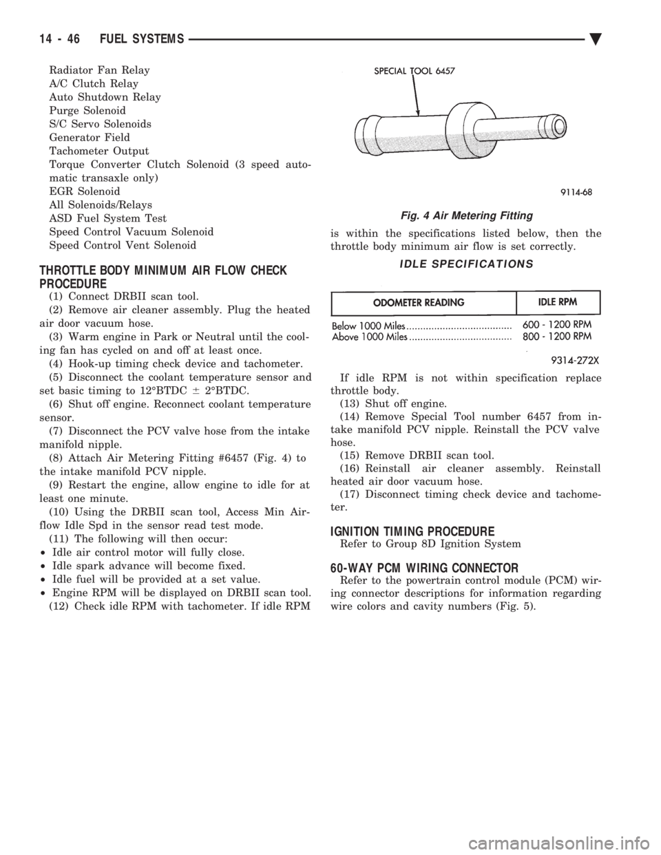
manifold nipple. (8) Attach Air Metering Fitting #6457 (Fig. 4) to
the intake manifold PCV nipple. (9) Restart the engine, allow engine to idle for at
least one minute. (10) Using the DRBII scan tool, Access Min Air-
flow Idle Spd in the sensor read test mode. (11) The following will then occur:
² Idle air control motor will fully close.
² Idle spark advance will become fixed.
² Idle fuel will be provided at a set value.
² Engine RPM will be displayed on DRBII scan tool.
(12) Check idle RPM with tachometer. If idle RPM is within the specifications listed below, then the
throttle body minimum air flow is set correctly.
If idle RPM is not within specification replace
throttle body. (13) Shut off engine.
(14) Remove Special Tool number 6457 from in-
take manifold PCV nipple. Reinstall the PCV valve
hose. (15) Remove DRBII scan tool.
(16) Reinstall air cleaner assembly. Reinstall
heated air door vacuum hose. (17) Disconnect timing check device and tachome-
ter.
IGNITION TIMING PROCEDURE
Refer to Group 8D Ignition System
60-WAY PCM WIRING CONNECTOR
Refer to the powertrain control module (PCM) wir-
ing connector descriptions for information regarding
wire colors and cavity numbers (Fig. 5).
Fig. 4 Air Metering Fitting
IDLE SPECIFICATIONS
14 - 46 FUEL SYSTEMS Ä
Page 1795 of 2438
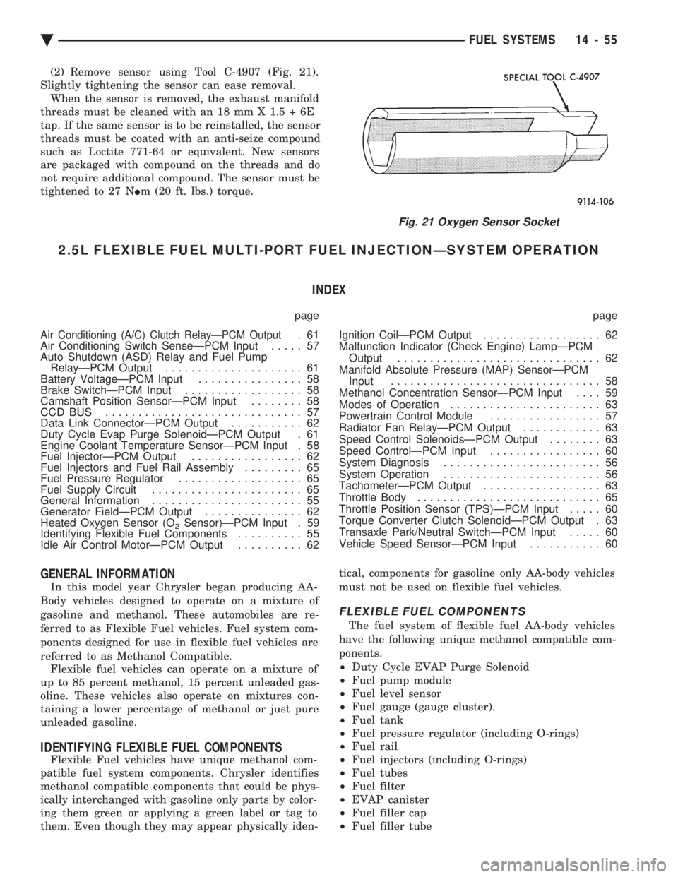
(2) Remove sensor using Tool C-4907 (Fig. 21).
Slightly tightening the sensor can ease removal. When the sensor is removed, the exhaust manifold
threads must be cleaned with an 18 mm X 1.5 + 6E
tap. If the same sensor is to be reinstalled, the sensor
threads must be coated with an anti-seize compound
such as Loctite 771-64 or equivalent. New sensors
are packaged with compound on the threads and do
not require additional compound. The sensor must be
tightened to 27 N Im (20 ft. lbs.) torque.
2.5L FLEXIBLE FUEL MULTI-PORT FUEL INJECTIONÐSYSTEM OPERATION
INDEX
page page
Air Conditioning (A/C) Clutch RelayÐPCM Output.61
Air Conditioning Switch SenseÐPCM Input ..... 57
Auto Shutdown (ASD) Relay and Fuel Pump RelayÐPCM Output ..................... 61
Battery VoltageÐPCM Input ................ 58
Brake SwitchÐPCM Input .................. 58
Camshaft Position SensorÐPCM Input ........ 58
CCD BUS .............................. 57
Data Link ConnectorÐPCM Output ........... 62
Duty Cycle Evap Purge SolenoidÐPCM Output . 61
Engine Coolant Temperature SensorÐPCM Input . 58
Fuel InjectorÐPCM Output ................. 62
Fuel Injectors and Fuel Rail Assembly ......... 65
Fuel Pressure Regulator ................... 65
Fuel Supply Circuit ....................... 65
General Information ....................... 55
Generator FieldÐPCM Output ............... 62
Heated Oxygen Sensor (O
2Sensor)ÐPCM Input . 59
Identifying Flexible Fuel Components .......... 55
Idle Air Control MotorÐPCM Output .......... 62 Ignition CoilÐPCM Output
.................. 62
Malfunction Indicator (Check Engine) LampÐPCM Output ............................... 62
Manifold Absolute Pressure (MAP) SensorÐPCM Input ................................ 58
Methanol Concentration SensorÐPCM Input .... 59
Modes of Operation ....................... 63
Powertrain Control Module ................. 57
Radiator Fan RelayÐPCM Output ............ 63
Speed Control SolenoidsÐPCM Output ........ 63
Speed ControlÐPCM Input ................. 60
System Diagnosis ........................ 56
System Operation ........................ 56
TachometerÐPCM Output .................. 63
Throttle Body ............................ 65
Throttle Position Sensor (TPS)ÐPCM Input ..... 60
Torque Converter Clutch SolenoidÐPCM Output . 63
Transaxle Park/Neutral SwitchÐPCM Input ..... 60
Vehicle Speed SensorÐPCM Input ........... 60
GENERAL INFORMATION
In this model year Chrysler began producing AA-
Body vehicles designed to operate on a mixture of
gasoline and methanol. These automobiles are re-
ferred to as Flexible Fuel vehicles. Fuel system com-
ponents designed for use in flexible fuel vehicles are
referred to as Methanol Compatible. Flexible fuel vehicles can operate on a mixture of
up to 85 percent methanol, 15 percent unleaded gas-
oline. These vehicles also operate on mixtures con-
taining a lower percentage of methanol or just pure
unleaded gasoline.
IDENTIFYING FLEXIBLE FUEL COMPONENTS
Flexible Fuel vehicles have unique methanol com-
patible fuel system components. Chrysler identifies
methanol compatible components that could be phys-
ically interchanged with gasoline only parts by color-
ing them green or applying a green label or tag to
them. Even though they may appear physically iden- tical, components for gasoline only AA-body vehicles
must not be used on flexible fuel vehicles.
FLEXIBLE FUEL COMPONENTS
The fuel system of flexible fuel AA-body vehicles
have the following unique methanol compatible com-
ponents.
² Duty Cycle EVAP Purge Solenoid
² Fuel pump module
² Fuel level sensor
² Fuel gauge (gauge cluster).
² Fuel tank
² Fuel pressure regulator (including O-rings)
² Fuel rail
² Fuel injectors (including O-rings)
² Fuel tubes
² Fuel filter
² EVAP canister
² Fuel filler cap
² Fuel filler tube
Fig. 21 Oxygen Sensor Socket
Ä FUEL SYSTEMS 14 - 55
Page 1797 of 2438
The second method of reading diagnostic trouble
codes uses the DRBII scan tool. For diagnostic trou-
ble code information, refer to the On-Board Diagnos-
tics section in this group.
CCD BUS
Various modules exchange information through a
communications port called the CCD Bus. The pow-
ertrain control module transmits vehicle load data on
the CCD Bus.
POWERTRAIN CONTROL MODULE
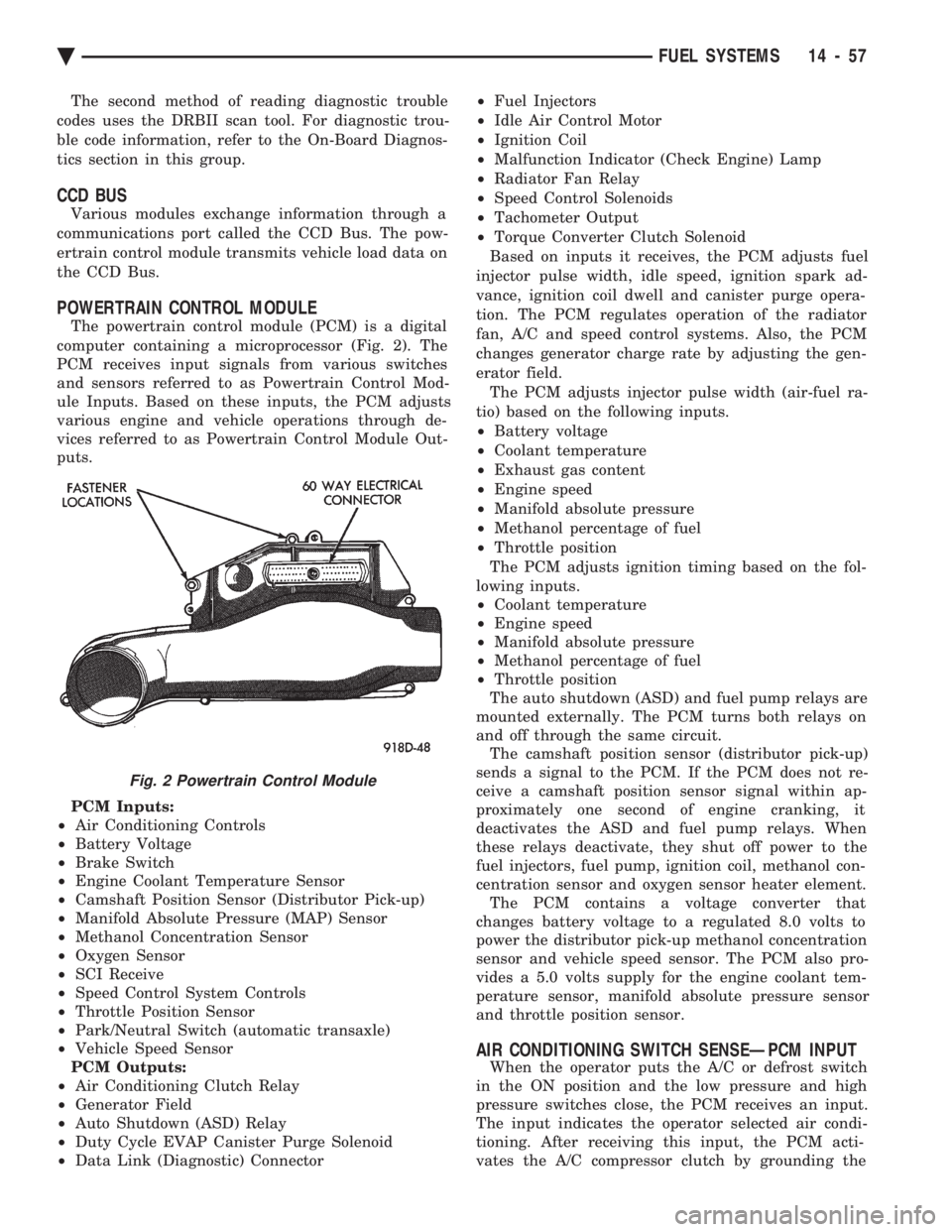
The powertrain control module (PCM) is a digital
computer containing a microprocessor (Fig. 2). The
PCM receives input signals from various switches
and sensors referred to as Powertrain Control Mod-
ule Inputs. Based on these inputs, the PCM adjusts
various engine and vehicle operations through de-
vices referred to as Powertrain Control Module Out-
puts.
PCM Inputs:
² Air Conditioning Controls
² Battery Voltage
² Brake Switch
² Engine Coolant Temperature Sensor
² Camshaft Position Sensor (Distributor Pick-up)
² Manifold Absolute Pressure (MAP) Sensor
² Methanol Concentration Sensor
² Oxygen Sensor
² SCI Receive
² Speed Control System Controls
² Throttle Position Sensor
² Park/Neutral Switch (automatic transaxle)
² Vehicle Speed Sensor
PCM Outputs:
² Air Conditioning Clutch Relay
² Generator Field
² Auto Shutdown (ASD) Relay
² Duty Cycle EVAP Canister Purge Solenoid
² Data Link (Diagnostic) Connector ²
Fuel Injectors
² Idle Air Control Motor
² Ignition Coil
² Malfunction Indicator (Check Engine) Lamp
² Radiator Fan Relay
² Speed Control Solenoids
² Tachometer Output
² Torque Converter Clutch Solenoid
Based on inputs it receives, the PCM adjusts fuel
injector pulse width, idle speed, ignition spark ad-
vance, ignition coil dwell and canister purge opera-
tion. The PCM regulates operation of the radiator
fan, A/C and speed control systems. Also, the PCM
changes generator charge rate by adjusting the gen-
erator field. The PCM adjusts injector pulse width (air-fuel ra-
tio) based on the following inputs.
² Battery voltage
² Coolant temperature
² Exhaust gas content
² Engine speed
² Manifold absolute pressure
² Methanol percentage of fuel
² Throttle position
The PCM adjusts ignition timing based on the fol-
lowing inputs.
² Coolant temperature
² Engine speed
² Manifold absolute pressure
² Methanol percentage of fuel
² Throttle position
The auto shutdown (ASD) and fuel pump relays are
mounted externally. The PCM turns both relays on
and off through the same circuit. The camshaft position sensor (distributor pick-up)
sends a signal to the PCM. If the PCM does not re-
ceive a camshaft position sensor signal within ap-
proximately one second of engine cranking, it
deactivates the ASD and fuel pump relays. When
these relays deactivate, they shut off power to the
fuel injectors, fuel pump, ignition coil, methanol con-
centration sensor and oxygen sensor heater element. The PCM contains a voltage converter that
changes battery voltage to a regulated 8.0 volts to
power the distributor pick-up methanol concentration
sensor and vehicle speed sensor. The PCM also pro-
vides a 5.0 volts supply for the engine coolant tem-
perature sensor, manifold absolute pressure sensor
and throttle position sensor.
AIR CONDITIONING SWITCH SENSEÐPCM INPUT
When the operator puts the A/C or defrost switch
in the ON position and the low pressure and high
pressure switches close, the PCM receives an input.
The input indicates the operator selected air condi-
tioning. After receiving this input, the PCM acti-
vates the A/C compressor clutch by grounding the
Fig. 2 Powertrain Control Module
Ä FUEL SYSTEMS 14 - 57