1993 CHEVROLET PLYMOUTH ACCLAIM coolant temperature
[x] Cancel search: coolant temperaturePage 1798 of 2438
A/C clutch relay. To compensate for increased engine
load, the PCM also adjusts idle speed to a scheduled
RPM.
BATTERY VOLTAGEÐPCM INPUT
The powertrain control module (PCM) monitors the
battery voltage input to determine fuel injector pulse
width and generator field control. If battery voltage
is low, the PCM increases injector pulse width to
compensate.
BRAKE SWITCHÐPCM INPUT
When the brake switch activates, the powertrain
control module (PCM) receives an input indicating
that the brakes are being applied. After receiving the
input, the PCM vents the speed control servo. Vent-
ing the servo turns the speed control system off.
ENGINE COOLANT TEMPERATURE SENSORÐPCM
INPUT
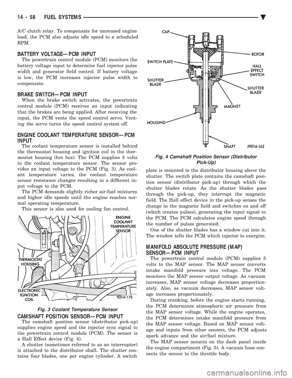
The coolant temperature sensor is installed behind
the thermostat housing and ignition coil in the ther-
mostat housing (hot box). The PCM supplies 5 volts
to the coolant temperature sensor. The sensor pro-
vides an input voltage to the PCM (Fig. 3). As cool-
ant temperature varies, the coolant temperature
sensor resistance changes resulting in a different in-
put voltage to the PCM. The PCM demands slightly richer air-fuel mixtures
and higher idle speeds until the engine reaches nor-
mal operating temperature. This sensor is also used for cooling fan control.
CAMSHAFT POSITION SENSORÐPCM INPUT
The camshaft position sensor (distributor pick-up)
supplies engine speed and the injector sync signal to
the powertrain control module (PCM). The sensor is
a Hall Effect device (Fig. 4). A shutter (sometimes referred to as an interrupter)
is attached to the distributor shaft. The shutter con-
tains four blades, one per engine cylinder. A switch plate is mounted to the distributor housing above the
shutter. The switch plate contains the camshaft posi-
tion sensor (distributor pick-up) through which the
shutter blades rotate. As the shutter blades pass
through the pick-up, they interrupt the magnetic
field. The Hall effect device in the pick-up senses the
change in the magnetic field and switches on and off
(which creates pulses), generating the input signal to
the PCM. The PCM calculates engine speed through
the number of pulses generated. One of the shutter blades has a window cut into it.
The window tells the PCM which injector to energize.
MANIFOLD ABSOLUTE PRESSURE (MAP)
SENSORÐPCM INPUT
The powertrain control module (PCM) supplies 5
volts to the MAP sensor. The MAP sensor converts
intake manifold pressure into voltage. The PCM
monitors the MAP sensor output voltage. As vacuum
increases, MAP sensor voltage decreases proportion-
ately. Also, as vacuum decreases, MAP sensor volt-
age increases proportionately. During cranking, before the engine starts running,
the PCM determines atmospheric air pressure from
the MAP sensor voltage. While the engine operates,
the PCM determines intake manifold pressure from
the MAP sensor voltage. Based on MAP sensor volt-
age and inputs from other sensors, the PCM adjusts
spark advance and the air/fuel mixture. The MAP sensor mounts on the dash panel inside
the engine compartment (Fig. 5). A vacuum hose con-
nects the sensor to the throttle body.
Fig. 3 Coolant Temperature Sensor
Fig. 4 Camshaft Position Sensor (Distributor Pick-Up)
14 - 58 FUEL SYSTEMS Ä
Page 1802 of 2438
ter mounting studs (Fig. 12). The top of the solenoid
has the word TOP on it. The solenoid will not oper-
ate unless it is installed correctly.
DATA LINK CONNECTORÐPCM OUTPUT
The data link connector provides the technician
with the means to connect the DRBII scan tool to di-
agnosis the vehicle.
FUEL INJECTORÐPCM OUTPUT
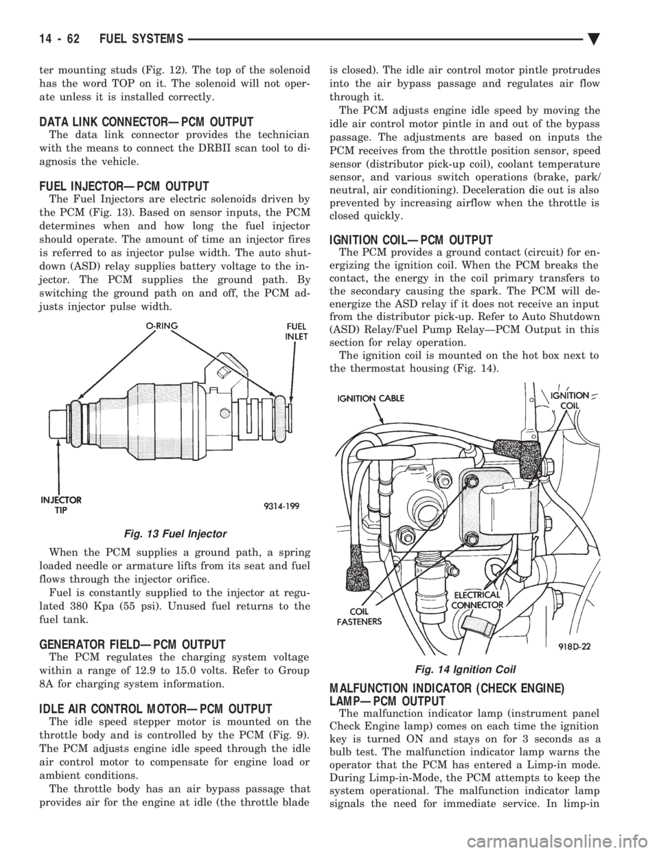
The Fuel Injectors are electric solenoids driven by
the PCM (Fig. 13). Based on sensor inputs, the PCM
determines when and how long the fuel injector
should operate. The amount of time an injector fires
is referred to as injector pulse width. The auto shut-
down (ASD) relay supplies battery voltage to the in-
jector. The PCM supplies the ground path. By
switching the ground path on and off, the PCM ad-
justs injector pulse width.
When the PCM supplies a ground path, a spring
loaded needle or armature lifts from its seat and fuel
flows through the injector orifice. Fuel is constantly supplied to the injector at regu-
lated 380 Kpa (55 psi). Unused fuel returns to the
fuel tank.
GENERATOR FIELDÐPCM OUTPUT
The PCM regulates the charging system voltage
within a range of 12.9 to 15.0 volts. Refer to Group
8A for charging system information.
IDLE AIR CONTROL MOTORÐPCM OUTPUT
The idle speed stepper motor is mounted on the
throttle body and is controlled by the PCM (Fig. 9).
The PCM adjusts engine idle speed through the idle
air control motor to compensate for engine load or
ambient conditions. The throttle body has an air bypass passage that
provides air for the engine at idle (the throttle blade is closed). The idle air control motor pintle protrudes
into the air bypass passage and regulates air flow
through it. The PCM adjusts engine idle speed by moving the
idle air control motor pintle in and out of the bypass
passage. The adjustments are based on inputs the
PCM receives from the throttle position sensor, speed
sensor (distributor pick-up coil), coolant temperature
sensor, and various switch operations (brake, park/
neutral, air conditioning). Deceleration die out is also
prevented by increasing airflow when the throttle is
closed quickly.
IGNITION COILÐPCM OUTPUT
The PCM provides a ground contact (circuit) for en-
ergizing the ignition coil. When the PCM breaks the
contact, the energy in the coil primary transfers to
the secondary causing the spark. The PCM will de-
energize the ASD relay if it does not receive an input
from the distributor pick-up. Refer to Auto Shutdown
(ASD) Relay/Fuel Pump RelayÐPCM Output in this
section for relay operation. The ignition coil is mounted on the hot box next to
the thermostat housing (Fig. 14).
MALFUNCTION INDICATOR (CHECK ENGINE)
LAMPÐPCM OUTPUT
The malfunction indicator lamp (instrument panel
Check Engine lamp) comes on each time the ignition
key is turned ON and stays on for 3 seconds as a
bulb test. The malfunction indicator lamp warns the
operator that the PCM has entered a Limp-in mode.
During Limp-in-Mode, the PCM attempts to keep the
system operational. The malfunction indicator lamp
signals the need for immediate service. In limp-in
Fig. 13 Fuel Injector
Fig. 14 Ignition Coil
14 - 62 FUEL SYSTEMS Ä
Page 1803 of 2438
mode, the PCM compensates for the failure of certain
components that send incorrect signals. The PCM
substitutes for the incorrect signals with inputs from
other sensors and by using stored default values.Signals that can trigger the Malfunction Indi-
cator (Check Engine) Lamp.
² An emission system component
² Battery Voltage Input
² Charging system
² Engine Coolant Temperature Sensor
² Manifold Absolute Pressure Sensor
² Methanol Concentration Sensor
² Throttle Position Sensor
The malfunction indicator lamp can also display
diagnostic trouble codes. Cycle the ignition switch on,
off, on, off, on, within five seconds and the PCM
displays any diagnostic trouble codes stored in
memory. Refer to the 2.5L Flexible Fuel Multi-Port
Fuel InjectionÐOn Board Diagnostics section in this
group for diagnostic trouble code descriptions.
RADIATOR FAN RELAYÐPCM OUTPUT
The radiator fan is energized by the PCM through
the radiator fan relay. The PCM grounds the radiator
fan relay when engine coolant reaches a predetermined
temperature. For more information, refer to Group 7,
Cooling Systems. The radiator fan relay is mounted on the drivers side
fender well, next to the strut tower (Fig. 11).
SPEED CONTROL SOLENOIDSÐPCM OUTPUT
The speed control vacuum and vent solenoids are
operated by the PCM. When the PCM supplies a
ground to the vacuum and vent solenoids, the speed
control system opens the throttle blade. When the PCM
supplies a ground only to the vent solenoid, the throttle
blade holds position. When the PCM removes the
ground from both the vacuum and vent solenoids, the
throttle blade closes. The PCM balances the two sole-
noids to maintain the set speed. Refer to Group 8H for
speed control information.
TACHOMETERÐPCM OUTPUT
The PCM supplies engine RPM to the instrument
panel tachometer. Refer to Group 8 for tachometer
information.
TORQUE CONVERTER CLUTCH SOLENOIDÐPCM
OUTPUT
Three-speed automatic transaxles use a torque con-
verter clutch solenoid. The PCM controls the lock-up of
the torque convertor through the solenoid. The tran-
saxle is locked up only in direct drive mode. Refer to
Group 21 for transaxle information.
MODES OF OPERATION
As input signals to the PCM change, the PCM
adjusts its response to the output devices. For example, the PCM must calculate a different injector pulse
width and ignition timing for idle than it does for wide
open throttle (WOT). There are several different modes
of operation that determine how the PCM responds to
the various input signals. There are two different areas of operation, Open
Loop and Closed Loop. During Open Loop modes, the PCM receives input
signals and responds according to preset PCM pro-
gramming. Input from the oxygen (O
2) sensor is not
monitored during Open Loop modes. During CLOSED LOOP modes, the PCM does moni-
tor the oxygen (O
2) sensor input. The input indicates if
the calculated injector pulse width results in the ideal
air-fuel ratio for the current percentage of methanol in
the fuel. By monitoring the exhaust oxygen content
through the O
2sensor, the PCM can fine tune the
injector pulse width to achieve optimum fuel economy
combined with low emissions. The 2.5L flexible fuel multi-port fuel injection system
has the following modes of operation:
² Ignition switch ON - Zero RPM
² Engine start-up
² Engine warm-up
² Cruise (Idle)
² Acceleration
² Deceleration
² Wide Open Throttle
² Ignition switch OFF
The engine start-up (crank), engine warm-up, and
wide open throttle modes are OPEN LOOP modes. The
acceleration, deceleration, and cruise modes, with the
engine at operating temperature are CLOSED
LOOP modes (under most operating conditions).
IGNITION SWITCH ON (ZERO RPM) MODE
When the ignition switch cycles and past the On
position, the fuel injection system activates and the
following actions occur:
² For two seconds at key ON (and during cranking),
the methanol concentration sensor calibrates the PCM.
During the calibration period the sensor sends 4.45
volts to the PCM as a correction factor. After the
calibration period, the methanol concentration sensor
output represents the methanol percentage in the fuel.
² The PCM calculates basic fuel strategy by determin-
ing atmospheric air pressure from the MAP sensor
input.
² The PCM monitors the coolant temperature sensor
and throttle position sensor input. The PCM modifies
fuel strategy based on this input. When the key is in the ON position and the engine is
not running, the auto shutdown (ASD) relay and fuel
pump relay are not energized. Therefore battery volt-
age is not supplied to the fuel pump, ignition coil, fuel
injector or oxygen sensor heating element.
Ä FUEL SYSTEMS 14 - 63
Page 1804 of 2438
ENGINE START-UP MODE
This is an OPEN LOOP mode. The following ac-
tions occur when the starter motor is engaged. The methanol concentration sensor finishes cali-
brating the PCM (takes approximately two seconds).
After the calibration period, the PCM determines the
methanol content of the fuel from the methanol con-
centration sensor input. If the PCM receives a camshaft position sensor
(distributor pick-up) signal it energizes the auto
shutdown (ASD) relay and fuel pump relay. These re-
lays supply battery voltage to the fuel injector, igni-
tion coil and oxygen sensor heating element. If the
PCM does not receive a camshaft position sensor sig-
nal, it de-energizes the ASD and fuel pump relays af-
ter approximately one second. With the engine idling within 664 RPM of the tar-
get RPM, the PCM compares the current MAP value
with the atmospheric pressure value it received dur-
ing the Ignition Switch On (Zero RPM) Mode. If a
minimum difference between the two is not detected,
a MAP sensor fault is set into memory. Once the ASD relay and fuel pump relay have en-
ergized, the PCM:
² Supplies a ground path to each injector. The injec-
tors are pulsed four times per engine revolution in-
stead of the normal two pulses per revolution.
² Determines injector pulse width based on engine
coolant temperature, methanol concentration sensor
input, MAP sensor input, throttle position, and the
number of engine revolutions since cranking was ini-
tiated.
² Monitors the coolant temperature sensor, camshaft
position sensor, MAP sensor, methanol concentration
sensor, and throttle position sensor to determine cor-
rect ignition timing.
ENGINE WARM-UP MODE
This is a OPEN LOOP mode. The following inputs
are received by the PCM:
² Engine coolant temperature
² Engine speed
² Manifold absolute pressure (MAP)
² Methanol percentage in fuel
² Throttle position
² A/C switch
² Battery voltage
The PCM determines the methanol content of the
fuel from the methanol concentration sensor input. The PCM provides a ground path for the injectors
and energizes them in sequence. The PCM precisely
controls injector pulse width by switching the ground
on and off. The PCM regulates engine idle speed by adjusting
the idle air control motor. Also, the PCM adjusts ig-
nition timing.
CRUISE OR IDLE MODE
When the engine is at operating temperature, this
is a CLOSED LOOP mode. During cruising speed the
following inputs are received by the PCM:
² Engine coolant temperature
² Manifold absolute pressure
² Methanol percentage in fuel
² Engine speed
² Throttle position
² Exhaust gas oxygen content
² A/C control positions
² Battery voltage
The PCM determines the methanol content of the
fuel from the methanol concentration sensor input. The PCM provides a ground path for the injectors
to precisely control injector pulse width. The PCM
controls engine idle speed and ignition timing. The
PCM controls the air/fuel ratio according to the oxy-
gen content in the exhaust gas.
ACCELERATION MODE
This is a CLOSED LOOP mode. The PCM recog-
nizes an abrupt increase in throttle position or MAP
pressure as a demand for increased engine output
and vehicle acceleration. The PCM increases injector
pulse width in response to increased fuel demand.
DECELERATION MODE
This is a CLOSED LOOP mode. During decelera-
tion the following inputs are received by the PCM:
² Engine coolant temperature
² Manifold absolute pressure
² Methanol percentage in fuel
² Engine speed
² Throttle position
² Exhaust gas oxygen content
² A/C control positions
² Battery voltage
The PCM may receive a closed throttle input from
the TPS at the same time it senses an abrupt de-
crease in manifold absolute pressure. This indicates a
hard deceleration. In response, the PCM may modify
the injector firing sequence. Modifying the injector
firing sequence helps maintain better control of the
air-fuel mixture (as sensed through the O
2sensor).
WIDE OPEN THROTTLE MODE
This is an OPEN LOOP mode. During wide open
throttle operation, the following inputs are received
by the PCM:
² Engine coolant temperature
² Manifold absolute pressure
² Methanol percentage in fuel
² Engine speed
² Throttle position
When the PCM senses a wide open throttle condi-
tion, it de-energizes the air conditioning clutch relay.
This disables the air conditioning system.
14 - 64 FUEL SYSTEMS Ä
Page 1807 of 2438
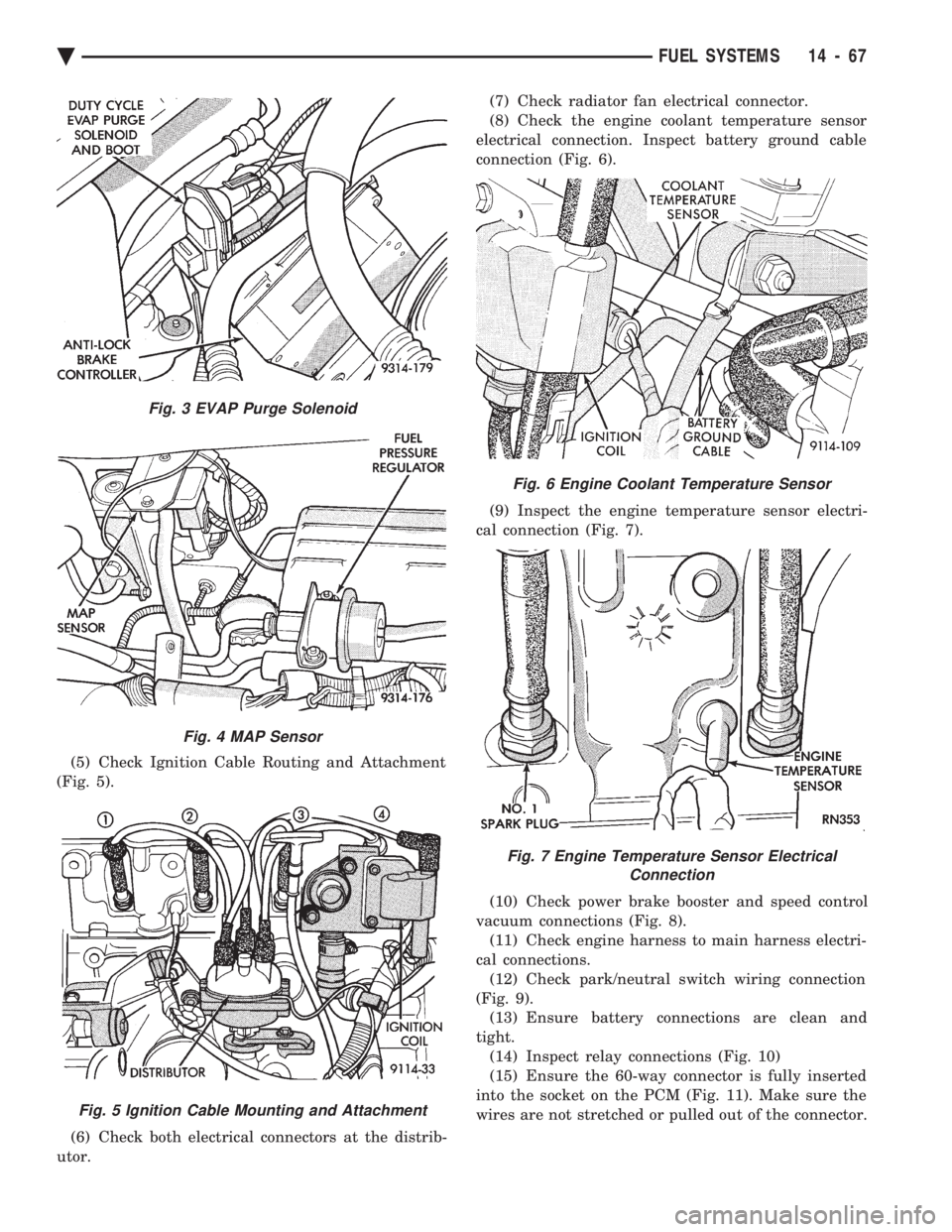
(5) Check Ignition Cable Routing and Attachment
(Fig. 5).
(6) Check both electrical connectors at the distrib-
utor. (7) Check radiator fan electrical connector.
(8) Check the engine coolant temperature sensor
electrical connection. Inspect battery ground cable
connection (Fig. 6).
(9) Inspect the engine temperature sensor electri-
cal connection (Fig. 7).
(10) Check power brake booster and speed control
vacuum connections (Fig. 8). (11) Check engine harness to main harness electri-
cal connections. (12) Check park/neutral switch wiring connection
(Fig. 9). (13) Ensure battery connections are clean and
tight. (14) Inspect relay connections (Fig. 10)
(15) Ensure the 60-way connector is fully inserted
into the socket on the PCM (Fig. 11). Make sure the
wires are not stretched or pulled out of the connector.
Fig. 3 EVAP Purge Solenoid
Fig. 4 MAP Sensor
Fig. 5 Ignition Cable Mounting and Attachment
Fig. 6 Engine Coolant Temperature Sensor
Fig. 7 Engine Temperature Sensor Electrical Connection
Ä FUEL SYSTEMS 14 - 67
Page 1812 of 2438
tween the flashes representing the first and second
digits of the code. Longer pauses separate individual
trouble codes.(3) Refer to the Diagnostic Trouble Code Charts at
the end of this group.
STATE DISPLAY TEST MODE
The switch inputs to the powertrain control module
(PCM) have two recognized states; HIGH and LOW.
For this reason, the PCM cannot recognize the differ-
ence between a selected switch position versus an
open circuit, a short circuit, or a defective switch. If
the State Display screen shows the change from
HIGH to LOW or LOW to HIGH, assume the entire
switch circuit to the PCM functions properly. From
the state display screen, access either State Display
Inputs and Outputs or State Display Sensors.
STATE DISPLAY INPUTS AND OUTPUTS
Connect the DRBII scan tool to the vehicle and ac-
cess the State Display screen. Then access Inputs and
Outputs. The following is a list of the engine control
system functions accessible through the Inputs and
Outputs screen.
² Park/Neutral Switch (automatic transaxle only)
² Speed Control Resume
² Speed Control On/Off
² Speed Control Set
² Brake Switch
² A/C Switch Sense
² S/C Vent Solenoid
² S/C Vacuum Solenoid
² A/C Clutch Relay
² Auto Shutdown Relay
² Radiator Fan Relay
² (Duty Cycle) EVAP Purge Solenoid
² Malfunction Indicator (Check Engine) Lamp
STATE DISPLAY SENSORS
Connect the DRBII scan tool to the vehicle and ac-
cess the State Display screen. Then access Sensor
Display. The following is a list of the engine control
system functions accessible through the Sensor Dis-
play screen.
² Oxygen Sensor Signal
² Engine Coolant Temperature
² Engine Coolant Temp Sensor
² Throttle Position
² Minimum Throttle
² Battery Voltage
² MAP Sensor Reading
² Idle Air Control Motor Position
² Adaptive Fuel Factor
² Barometric Pressure
² Min Airflow Idle Spd (Speed)
² Engine Speed
² Fault #1 Key-On Info
² Module Spark Advance ²
Speed Control Target
² Fault #2 Key-on Info
² Fault #3 Key-on Info
² Speed Control Status
² Charging System Goal
² Theft Alarm Status
² Battery Temperature
² Flex Fuel (Methanol Concentration) Sensor Volt-
age
² Methanol Content (percentage)
² Map Sensor Voltage
² Vehicle Speed
² Oxygen Sensor State
² MAP Gauge Reading
² Throttle Opening (percentage)
² Total Spark Advance
CIRCUIT ACTUATION TEST MODE
The Circuit Actuation Test Mode checks for proper
operation of output circuits or devices the powertrain
control module (PCM) cannot internally recognize.
The PCM attempts to activate these outputs and al-
low an observer to verify proper operation. Most of
the tests provide an audible or visual indication of
device operation (click of relay contacts, fuel spray,
etc.). Except for intermittent conditions, if a device
functions properly during testing, assume the device,
its associated wiring, and driver circuit work cor-
rectly.
OBTAINING CIRCUIT ACTUATION TEST
Connect the DRBII scan tool to the vehicle and ac-
cess the Actuators screen. The following is a list of
the engine control system functions accessible
through Actuators screens. Subordinate screens for
each actuator test are also listed. Stop All Tests
Ignition Coil No. 1
Fuel Injector No. 1
Fuel Injector No. 2
Fuel Injector No. 3
Fuel Injector No. 4
Idle Air Control Motor Open/Close
Fuel System
Radiator Fan Relay
A/C Clutch Relay
Auto Shutdown Relay
EVAP Purge Solenoid
Speed Control Servo Solenoids
Generator Field
Tachometer Output
Torque Converter Clutch Solenoid
All Solenoids/Relays
Speed Control Vent Solenoid
Speed Control Vacuum Solenoid
ASD Fuel System Test
14 - 72 FUEL SYSTEMS Ä
Page 1813 of 2438
THROTTLE BODY MINIMUM AIR FLOW CHECK
PROCEDURE
(1) Warm engine in Park or neutral until the cooling
fan has cycled on and off at least once. (2) Hook-up timing check device and Tachometer.
(3) Disconnect the coolant temperature sensor and
set basic timing to 12É BTDC 62É BTDC.
(4) Shut off engine. Connect harness connector to
coolant temperature sensor. (5) Disconnect the PCV valve hose from the nipple
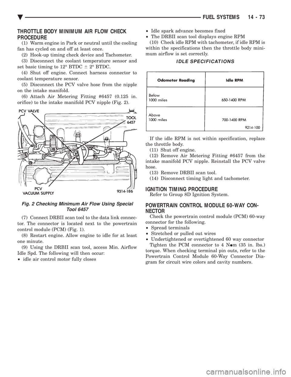
on the intake manifold. (6) Attach Air Metering Fitting #6457 (0.125 in.
orifice) to the intake manifold PCV nipple (Fig. 2).
(7) Connect DRBII scan tool to the data link connec-
tor. The connector is located next to the powertrain
control module (PCM) (Fig. 1). (8) Restart engine. Allow engine to idle for at least
one minute. (9) Using the DRBII scan tool, access Min. Airflow
Idle Spd. The following will then occur:
² idle air control motor fully closes ²
Idle spark advance becomes fixed
² The DRBII scan tool displays engine RPM
(10) Check idle RPM with tachometer, if idle RPM is
within the specifications then the throttle body mini-
mum airflow is set correctly.
If the idle RPM is not within specification, replace
the throttle body. (11) Shut off engine.
(12) Remove Air Metering Fitting #6457 from the
intake manifold PCV nipple. Reinstall the PCV valve
hose. (13) Remove DRBII scan tool.
(14) Disconnect timing light and tachometer.
IGNITION TIMING PROCEDURE
Refer to Group 8D Ignition System.
POWERTRAIN CONTROL MODULE 60-WAY CON-
NECTOR
Check the powertrain control module (PCM) 60-way
connector for the following.
² Spread terminals
² Stretched or pulled out wires
² Undertightened or overtightened 60 way connector
Tighten the PCM connector to 4 N Im (35 in. lbs.)
torque. When checking terminal pin outs, refer to the
Powertrain Control Module 60-Way Connector Dia-
gram for circuit wire colors and cavity numbers.
Fig. 2 Checking Minimum Air Flow Using Special Tool 6457
IDLE SPECIFICATIONS
Ä FUEL SYSTEMS 14 - 73
Page 1823 of 2438
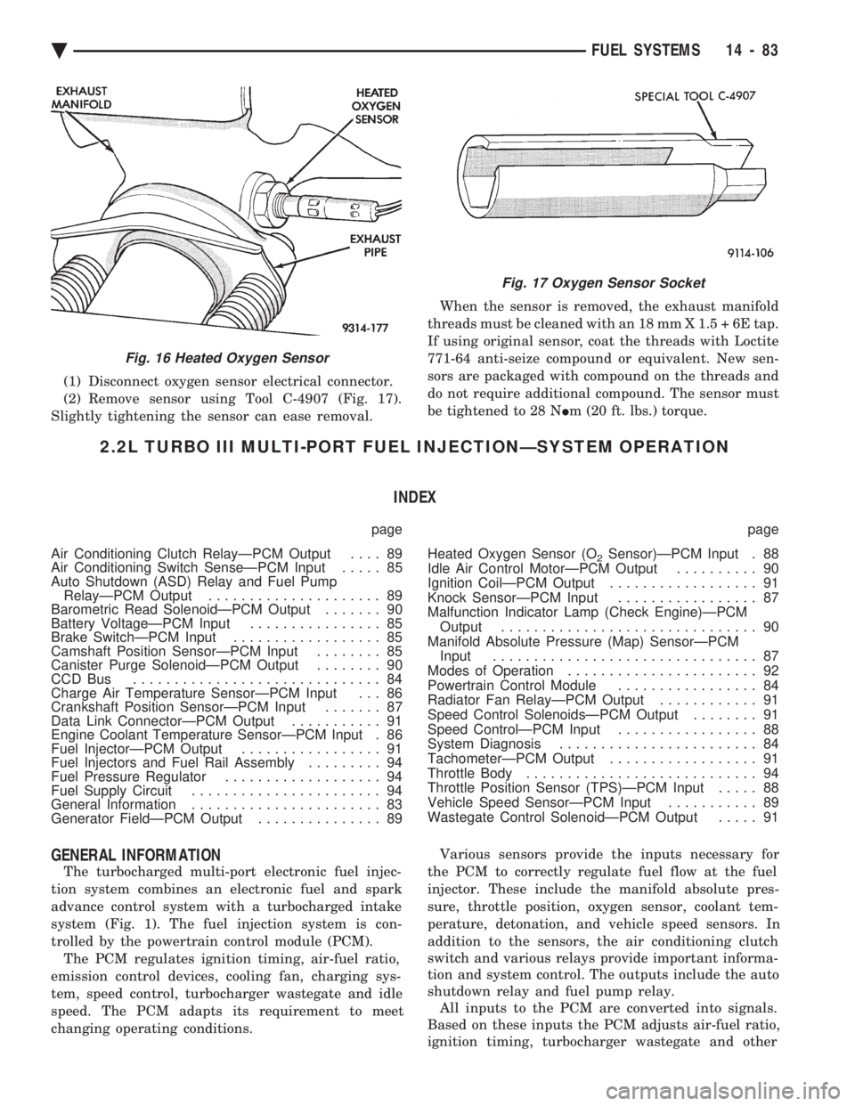
(1) Disconnect oxygen sensor electrical connector.
(2) Remove sensor using Tool C-4907 (Fig. 17).
Slightly tightening the sensor can ease removal. When the sensor is removed, the exhaust manifold
threads must be cleaned with an 18 mm X 1.5 + 6E tap.
If using original sensor, coat the threads with Loctite
771-64 anti-seize compound or equivalent. New sen-
sors are packaged with compound on the threads and
do not require additional compound. The sensor must
be tightened to 28 N Im (20 ft. lbs.) torque.
2.2L TURBO III MULTI-PORT FUEL INJECTIONÐSYSTEM OPERATION
INDEX
page page
Air Conditioning Clutch RelayÐPCM Output .... 89
Air Conditioning Switch SenseÐPCM Input ..... 85
Auto Shutdown (ASD) Relay and Fuel Pump RelayÐPCM Output ..................... 89
Barometric Read SolenoidÐPCM Output ....... 90
Battery VoltageÐPCM Input ................ 85
Brake SwitchÐPCM Input .................. 85
Camshaft Position SensorÐPCM Input ........ 85
Canister Purge SolenoidÐPCM Output ........ 90
CCD Bus .............................. 84
Charge Air Temperature SensorÐPCM Input . . . 86
Crankshaft Position SensorÐPCM Input ....... 87
Data Link ConnectorÐPCM Output ........... 91
Engine Coolant Temperature SensorÐPCM Input . 86
Fuel InjectorÐPCM Output ................. 91
Fuel Injectors and Fuel Rail Assembly ......... 94
Fuel Pressure Regulator ................... 94
Fuel Supply Circuit ....................... 94
General Information ....................... 83
Generator FieldÐPCM Output ............... 89 Heated Oxygen Sensor (O
2Sensor)ÐPCM Input . 88
Idle Air Control MotorÐPCM Output .......... 90
Ignition CoilÐPCM Output .................. 91
Knock SensorÐPCM Input ................. 87
Malfunction Indicator Lamp (Check Engine)ÐPCM Output ............................... 90
Manifold Absolute Pressure (Map) SensorÐPCM Input ................................ 87
Modes of Operation ....................... 92
Powertrain Control Module ................. 84
Radiator Fan RelayÐPCM Output ............ 91
Speed Control SolenoidsÐPCM Output ........ 91
Speed ControlÐPCM Input ................. 88
System Diagnosis ........................ 84
TachometerÐPCM Output .................. 91
Throttle Body ............................ 94
Throttle Position Sensor (TPS)ÐPCM Input ..... 88
Vehicle Speed SensorÐPCM Input ........... 89
Wastegate Control SolenoidÐPCM Output ..... 91
GENERAL INFORMATION
The turbocharged multi-port electronic fuel injec-
tion system combines an electronic fuel and spark
advance control system with a turbocharged intake
system (Fig. 1). The fuel injection system is con-
trolled by the powertrain control module (PCM). The PCM regulates ignition timing, air-fuel ratio,
emission control devices, cooling fan, charging sys-
tem, speed control, turbocharger wastegate and idle
speed. The PCM adapts its requirement to meet
changing operating conditions. Various sensors provide the inputs necessary for
the PCM to correctly regulate fuel flow at the fuel
injector. These include the manifold absolute pres-
sure, throttle position, oxygen sensor, coolant tem-
perature, detonation, and vehicle speed sensors. In
addition to the sensors, the air conditioning clutch
switch and various relays provide important informa-
tion and system control. The outputs include the auto
shutdown relay and fuel pump relay. All inputs to the PCM are converted into signals.
Based on these inputs the PCM adjusts air-fuel ratio,
ignition timing, turbocharger wastegate and other
Fig. 16 Heated Oxygen Sensor
Fig. 17 Oxygen Sensor Socket
Ä FUEL SYSTEMS 14 - 83