1993 CHEVROLET PLYMOUTH ACCLAIM oil pressure
[x] Cancel search: oil pressurePage 474 of 2438

The coil's low primary resistance allows the PCM to
fully charge the coil for each firing.
COOLANT TEMPERATURE SENSOR
On 2.2L Turbo III engines, the coolant temperature
sensor is installed into the thermostat housing (Fig. 30).
On 3.3L and 3.8L engines, the coolant temperature sensor
is located next to the thermostat housing (Fig. 31).
The coolant temperature sensor provides an input
voltage to the powertrain control module (PCM). The
sensor is a variable resistance (thermistor) with a
range of -40ÉC to 130ÉC (-40ÉF to 265ÉF). As coolant
temperature varies, the sensor resistance changes,
resulting in a different input voltage to the PCM.
The PCM contains different spark advance schedules
for cold and warm engine operation. The schedules reduce
engine emission and improve driveability.
The PCM demands slightly richer air-fuel mixtures
and higher idle speeds until the engine reaches normal
operating temperature. The coolant sensor input is also used for cooling
fan control.
KNOCK SENSORÐTURBO III ENGINE
Turbo III engines use a knock sensor. The sensor gen-
erates a signal when spark detonation occurs in the
combustion chambers. The sensor is mounted on the in-
take manifold behind the PCV breather (Fig. 32). The
sensor provides input voltage used by the powertrain
control module (PCM) to modify spark advance and
boost schedules in order to eliminate detonation.
MANIFOLD ABSOLUTE PRESSURE (MAP) SENSOR
The MAP sensor reacts to absolute pressure in the
intake manifold and provides an input voltage to the
powertrain control module (PCM). As engine load
changes, manifold pressure varies. The changes in
engine load cause the MAP output voltage to change.
The change in MAP sensor output voltage results in
a different input voltage to the PCM.
The input voltage level supplies the PCM with infor-
mation relating to ambient barometric pressure during
engine start-up (cranking) and engine load while its op-
erating. The PCM uses this input along with inputs
from other sensors to adjust air-fuel mixture.
On Turbo III engines, the MAP sensor is mounted
to the front right fender (Fig. 33) On 3.3L and 3.8L
engines, the MAP sensor (Fig. 34) is mounted to the
side of the intake manifold, below the positive crank-
case ventilation (PCV) valve. The sensor is connected
to the PCM electrically.
AUTO SHUTDOWN (ASD) RELAY AND FUEL PUMP
RELAY
The powertrain control module (PCM) operates the
auto shutdown (ASD) relay and fuel pump relay
through one ground path. The PCM operates the re-
lays by switching the ground path on and off. Both
relays turn on and off at the same time.
Fig. 32 Knock SensorÐTurbo III Engine
Fig. 30 Coolant Temperature SensorÐTurbo III En- gines
Fig. 31 Coolant Temperature SensorÐ3.3L and 3.8LEngines
8D - 32 IGNITION SYSTEMS Ä
Page 477 of 2438

2.2L TURBO III, 3.3L AND 3.8L IGNITION SYSTEMÐDIAGNOSTIC PROCEDURES INDEX
page page
Check Coil TestÐ3.3L and 3.8L Engines ...... 36
Check Coil TestÐTurbo III Engine ........... 35
Coolant Temperature Sensor Test ............ 38
Crankshaft Position Sensor and Camshaft Position Sensor Tests .......................... 38 Failure to Start Test
...................... 37
Failure to Start TestÐTurbo III Engine ........ 36
Manifold Absolute Pressure (MAP) Sensor Test . 38
Testing for Spark at CoilÐ3.3L and 3.8L Engines . 36
Testing for Spark at CoilÐTurbo III Engine ..... 35
TESTING FOR SPARK AT COILÐTURBO III ENGINE
WARNING: THE DIRECT IGNITION SYSTEM GENER-
ATES APPROXIMATELY 40,000 VOLTS. PERSONAL
INJURY COULD RESULT FROM CONTACT WITH
THIS SYSTEM.
The coil pack contains 2 independent coils. Each
coil must be checked individually.
CAUTION: Spark plug wire damage may occur if the
spark plug is moved more than 1/4 inch away from
the engine ground.
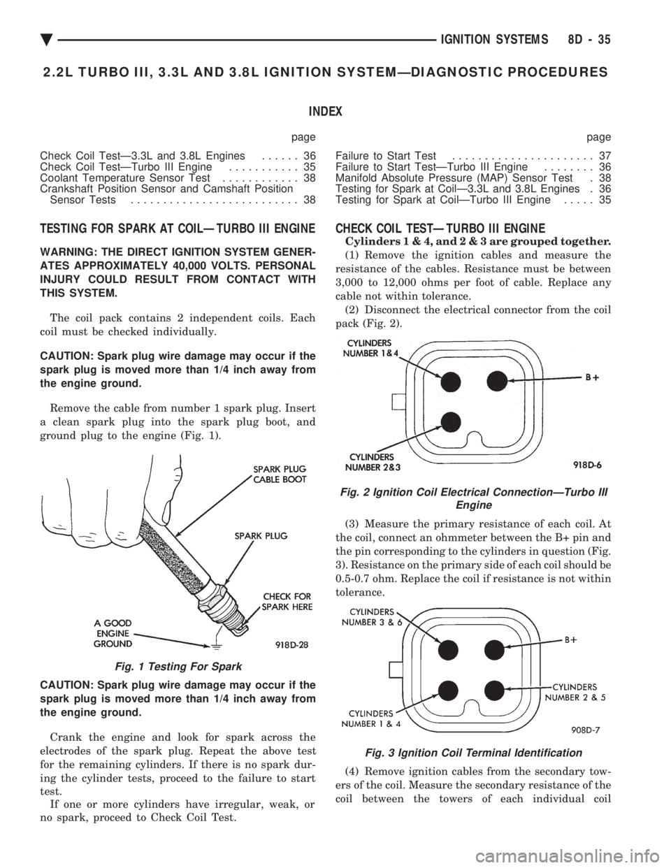
Remove the cable from number 1 spark plug. Insert
a clean spark plug into the spark plug boot, and
ground plug to the engine (Fig. 1).
CAUTION: Spark plug wire damage may occur if the
spark plug is moved more than 1/4 inch away from
the engine ground. Crank the engine and look for spark across the
electrodes of the spark plug. Repeat the above test
for the remaining cylinders. If there is no spark dur-
ing the cylinder tests, proceed to the failure to start
test. If one or more cylinders have irregular, weak, or
no spark, proceed to Check Coil Test.
CHECK COIL TESTÐTURBO III ENGINE
Cylinder s1&4,and2&3are grouped together.
(1) Remove the ignition cables and measure the
resistance of the cables. Resistance must be between
3,000 to 12,000 ohms per foot of cable. Replace any
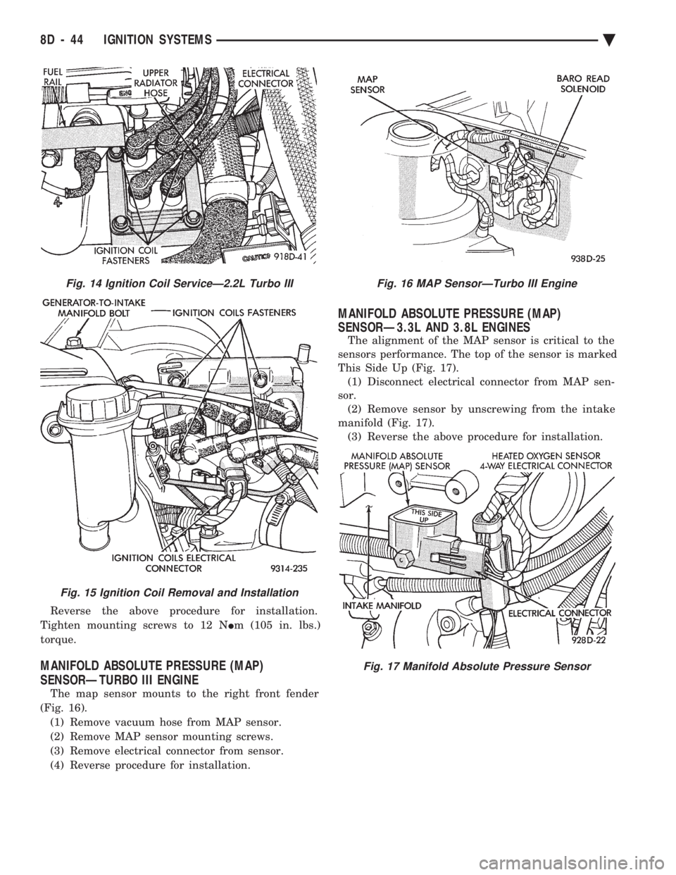
cable not within tolerance. (2) Disconnect the electrical connector from the coil
pack (Fig. 2).
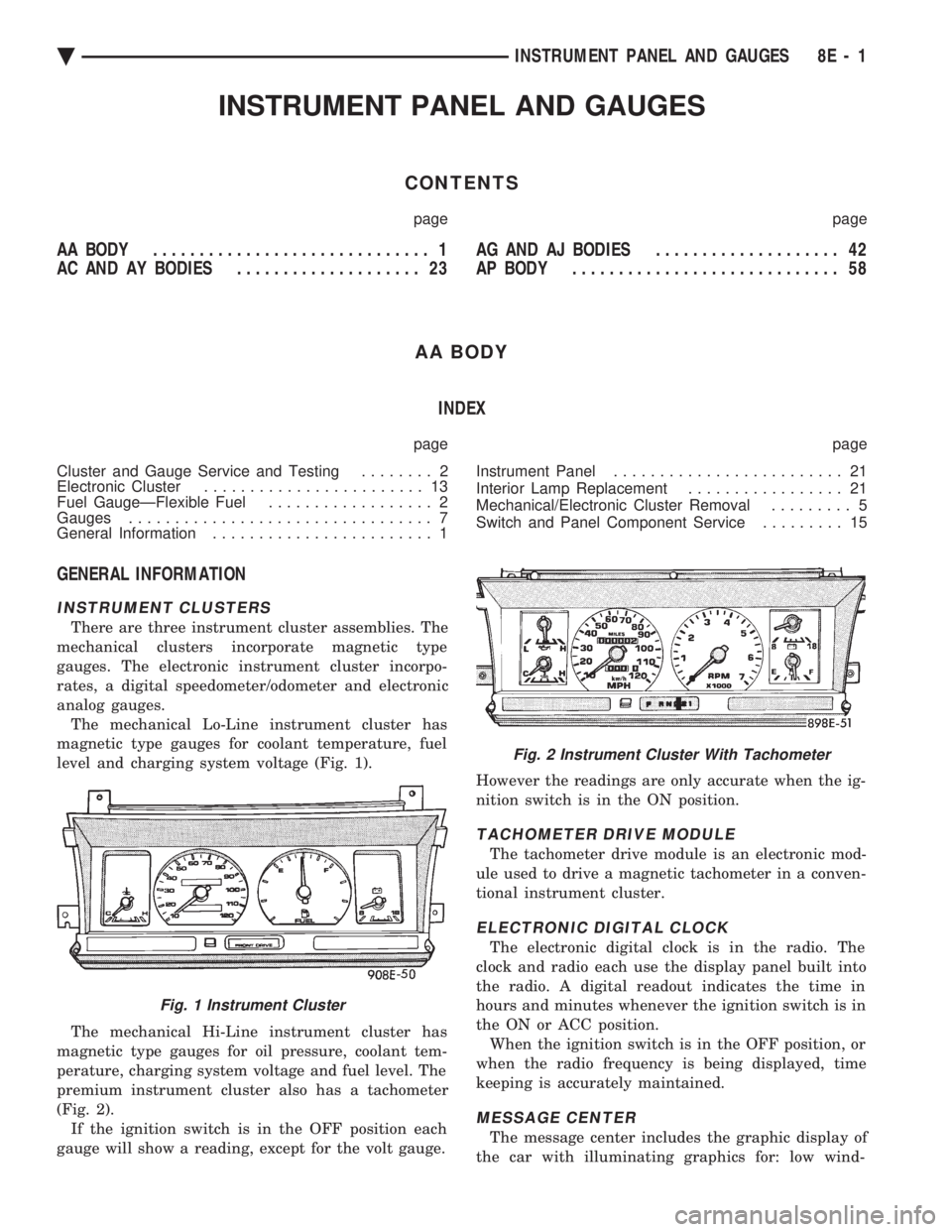
(3) Measure the primary resistance of each coil. At
the coil, connect an ohmmeter between the B+ pin and
the pin corresponding to the cylinders in question (Fig.
3). Resistance on the primary side of each coil should be
0.5-0.7 ohm. Replace the coil if resistance is not within
tolerance.
(4) Remove ignition cables from the secondary tow-
ers of the coil. Measure the secondary resistance of the
coil between the towers of each individual coil
Fig. 1 Testing For Spark
Fig. 2 Ignition Coil Electrical ConnectionÐTurbo III Engine
Fig. 3 Ignition Coil Terminal Identification
Ä IGNITION SYSTEMS 8D - 35
Page 481 of 2438

2.2L TURBO III, 3.3L AND 3.8L IGNITION SYSTEMSÐSERVICE PROCEDURES INDEX
page page
Camshaft Position Sensor ServiceÐTurbo III Engine.42Camshaft Position SensorÐ3.3L and 3.8L Engines.43
Coolant Temperature SensorÐ3.3L and 3.8L Engines .............................. 39
Coolant Temperature SensorÐTurbo III ........ 39
Crankshaft Position SensorÐ3.3L and 3.8L Engines.42
Crankshaft Position SensorÐTurbo III Engine . . . 42
Idle RPM Test ........................... 41
Ignition Coil ServiceÐTurbo III Engine ........ 43 Ignition CoilÐ3.3L and 3.8L Engine
........... 43
Knock SensorÐTurbo III Engines ............ 40
Manifold Absolute Pressure (MAP) SensorÐ3.3L and 3.8L Engines ....................... 44
Manifold Absolute Pressure (MAP) SensorÐ Turbo III Engine ........................ 44
Powertrain Control Module (PCM) ............ 39
Spark Plug Cable Service .................. 40
Spark Plug Service ....................... 41
POWERTRAIN CONTROL MODULE (PCM)
REMOVAL
(1) Remove air cleaner duct or air cleaner assem-
bly. (2) Remove battery.
(3) Remove powertrain control module (PCM)
mounting screws (Fig. 1). (4) Remove 60-way connector from PCM. Remove
PCM.
INSTALLATION
(1) Connect 60-Way connector to PCM (Fig. 1).
(2) Install PCM on inside left front fender. Install
and tighten mounting screws. (3) Install the battery.
(4) Install air cleaner duct or air cleaner assembly.
COOLANT TEMPERATURE SENSORÐTURBO III
The coolant sensor threads into the thermostat
housing (Fig. 2).
REMOVAL
(1) Drain cooling system until coolant level is be-
low thermostat housing. Refer to Group 7, Cooling
System. (2) Remove air cleaner fresh air duct.
(3) Disconnect electrical connector from coolant
sensor. (4) Remove sensor from thermostat housing (Fig.
2).
INSTALLATION
(1) Install sensor. Tighten to 7 N Im (60 in. lbs.)
torque. (2) Connect electrical connector to coolant sensor
(3) Fill cooling system. Refer to Group 7, Cooling
System. (4) Install fresh air duct.
COOLANT TEMPERATURE SENSORÐ3.3L AND
3.8L ENGINES
The coolant temperature sensor is located below
the ignition coil (Fig. 3).
REMOVAL
(1) Drain cooling system until coolant level is be-
low coolant sensor. Refer to Group 7, Cooling System. (2) Remove electrical connector from coil (Fig. 4).
(3) Remove coil mounting screws.
(4) Rotate coil away from coolant temperature sen-
sor.
Fig. 1 Powertrain Control Module (PCM)
Fig. 2 Coolant Temperature SensorÐTurbo III
Ä IGNITION SYSTEMS 8D - 39
Page 486 of 2438

Reverse the above procedure for installation.
Tighten mounting screws to 12 N Im (105 in. lbs.)
torque.
MANIFOLD ABSOLUTE PRESSURE (MAP)
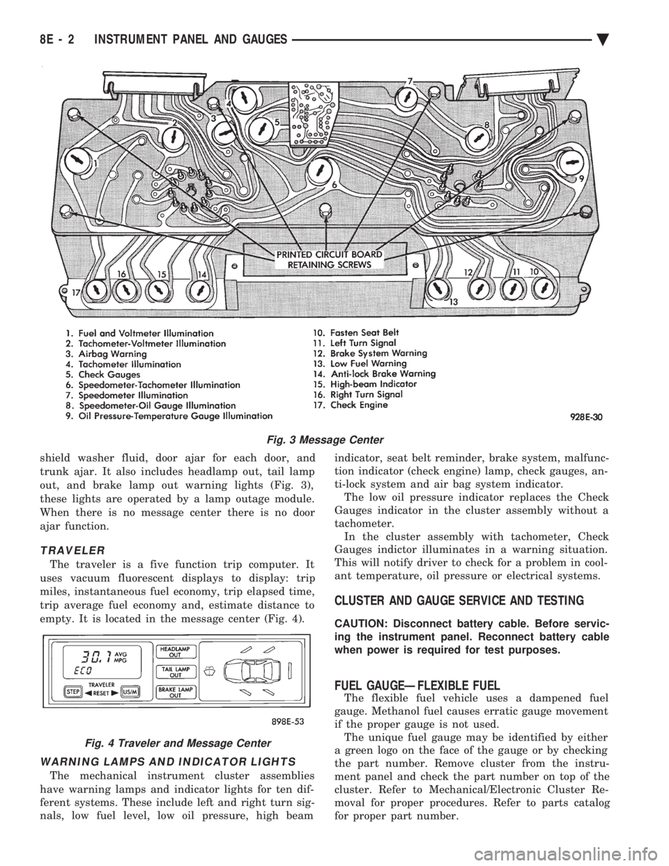
SENSORÐTURBO III ENGINE
The map sensor mounts to the right front fender
(Fig. 16). (1) Remove vacuum hose from MAP sensor.
(2) Remove MAP sensor mounting screws.
(3) Remove electrical connector from sensor.
(4) Reverse procedure for installation.
MANIFOLD ABSOLUTE PRESSURE (MAP)
SENSORÐ3.3L AND 3.8L ENGINES
The alignment of the MAP sensor is critical to the
sensors performance. The top of the sensor is marked
This Side Up (Fig. 17). (1) Disconnect electrical connector from MAP sen-
sor. (2) Remove sensor by unscrewing from the intake
manifold (Fig. 17). (3) Reverse the above procedure for installation.
Fig. 14 Ignition Coil ServiceÐ2.2L Turbo III
Fig. 15 Ignition Coil Removal and Installation
Fig. 16 MAP SensorÐTurbo III Engine
Fig. 17 Manifold Absolute Pressure Sensor
8D - 44 IGNITION SYSTEMS Ä
Page 493 of 2438

INSTRUMENT PANEL AND GAUGES
CONTENTS
page page
AA BODY .............................. 1
AC AND AY BODIES .................... 23 AG AND AJ BODIES
.................... 42
AP BODY ............................. 58
AA BODY INDEX
page page
Cluster and Gauge Service and Testing ........ 2
Electronic Cluster ........................ 13
Fuel GaugeÐFlexible Fuel .................. 2
Gauges ................................. 7
General Information ........................ 1 Instrument Panel
......................... 21
Interior Lamp Replacement ................. 21
Mechanical/Electronic Cluster Removal ......... 5
Switch and Panel Component Service ......... 15
GENERAL INFORMATION
INSTRUMENT CLUSTERS
There are three instrument cluster assemblies. The
mechanical clusters incorporate magnetic type
gauges. The electronic instrument cluster incorpo-
rates, a digital speedometer/odometer and electronic
analog gauges. The mechanical Lo-Line instrument cluster has
magnetic type gauges for coolant temperature, fuel
level and charging system voltage (Fig. 1).
The mechanical Hi-Line instrument cluster has
magnetic type gauges for oil pressure, coolant tem-
perature, charging system voltage and fuel level. The
premium instrument cluster also has a tachometer
(Fig. 2). If the ignition switch is in the OFF position each
gauge will show a reading, except for the volt gauge. However the readings are only accurate when the ig-
nition switch is in the ON position.
TACHOMETER DRIVE MODULE
The tachometer drive module is an electronic mod-
ule used to drive a magnetic tachometer in a conven-
tional instrument cluster.
ELECTRONIC DIGITAL CLOCK
The electronic digital clock is in the radio. The
clock and radio each use the display panel built into
the radio. A digital readout indicates the time in
hours and minutes whenever the ignition switch is in
the ON or ACC position. When the ignition switch is in the OFF position, or
when the radio frequency is being displayed, time
keeping is accurately maintained.
MESSAGE CENTER
The message center includes the graphic display of
the car with illuminating graphics for: low wind-
Fig. 1 Instrument Cluster
Fig. 2 Instrument Cluster With Tachometer
Ä INSTRUMENT PANEL AND GAUGES 8E - 1
Page 494 of 2438

shield washer fluid, door ajar for each door, and
trunk ajar. It also includes headlamp out, tail lamp
out, and brake lamp out warning lights (Fig. 3),
these lights are operated by a lamp outage module.
When there is no message center there is no door
ajar function.
TRAVELER
The traveler is a five function trip computer. It
uses vacuum fluorescent displays to display: trip
miles, instantaneous fuel economy, trip elapsed time,
trip average fuel economy and, estimate distance to
empty. It is located in the message center (Fig. 4).
WARNING LAMPS AND INDICATOR LIGHTS
The mechanical instrument cluster assemblies
have warning lamps and indicator lights for ten dif-
ferent systems. These include left and right turn sig-
nals, low fuel level, low oil pressure, high beam indicator, seat belt reminder, brake system, malfunc-
tion indicator (check engine) lamp, check gauges, an-
ti-lock system and air bag system indicator. The low oil pressure indicator replaces the Check
Gauges indicator in the cluster assembly without a
tachometer. In the cluster assembly with tachometer, Check
Gauges indictor illuminates in a warning situation.
This will notify driver to check for a problem in cool-
ant temperature, oil pressure or electrical systems.
CLUSTER AND GAUGE SERVICE AND TESTING
CAUTION: Disconnect battery cable. Before servic-
ing the instrument panel. Reconnect battery cable
when power is required for test purposes.
FUEL GAUGEÐFLEXIBLE FUEL
The flexible fuel vehicle uses a dampened fuel
gauge. Methanol fuel causes erratic gauge movement
if the proper gauge is not used. The unique fuel gauge may be identified by either
a green logo on the face of the gauge or by checking
the part number. Remove cluster from the instru-
ment panel and check the part number on top of the
cluster. Refer to Mechanical/Electronic Cluster Re-
moval for proper procedures. Refer to parts catalog
for proper part number.
Fig. 3 Message Center
Fig. 4 Traveler and Message Center
8E - 2 INSTRUMENT PANEL AND GAUGES Ä
Page 495 of 2438

SENDING UNIT TEST
When a problem occurs with a cluster gauge, be-
fore disassembling the cluster to check the gauge,
check for a defective sending unit or wiring. (1) Sending units and wiring can be checked by
grounding the connector leads, at the sending unit,
in the vehicle. (2) With the ignition in the ON position; a
grounded input will cause the oil, fuel or tempera-
ture gauge to read at or above maximum.
LOW OIL PRESSURE/CHECK GAUGES WARNING LAMP TEST
The low oil pressure/check gauges warning lamp
will illuminate when the ignition key is turned to
the ON position without starting the vehicle. In the cluster assembly without tachometer, the
low oil pressure lamp will illuminate if the engine oil
pressure drops below a safe oil pressure level. In the cluster assembly with tachometer, the Check
Gauges warning lamp illuminates when there is a
problem in oil pressure level, high engine tempera-
ture or low voltage. To test the system turn ignition key to the ON po-
sition. If the lamp fails to light, inspect for a broken
or disconnected wire at the oil pressure combination
unit, which is located at the front of the engine (Figs.
5 and 6). If the wire at the connector checks good,
pull connector loose from the switch terminal and
with a jumper wire ground connector to the engine
(Fig. 7). With the ignition key turned to the ON po-
sition check the warning lamp. If lamp still fails to
light, inspect for a burned out lamp or disconnected
socket in the cluster.
COMBINATION OIL UNIT TEST
The combination oil unit has two functions:
(1) The normal closed circuit keeps the oil pressure
warning/check gauges lamp on until there is oil pres-
sure (Fig. 7). (2) The sending unit provides a resistance that
varies with oil pressure. (3) To test the normally closed oil lamp circuit, dis-
connect the locking connector and measure the resis-
tance between the switch terminal and the metal
housing. The ohmmeter should read 0 ohms. Start
the engine. (4) If there is oil pressure, the ohmmeter should
read an open circuit. (5) To test the sending unit, measure the resis-
tance between the sending unit terminal and the
metal housing. The ohmmeter should read open.
Start the engine. (6) The ohmmeter should read between 30 to 55
ohms, depending on engine speed, oil temperature,
and oil viscosity. (7) If the above results are not obtained, replace
the switch.
BRAKE SYSTEM WARNING LAMP TEST
The brake warning lamp illuminates when parking
brake is applied with ignition key turned ON. The
same lamp will also illuminate should one of the two
service brake systems fail when brake pedal is ap-
plied. To test system turn ignition key ON, and ap-
ply parking brake. If lamp fails to light, inspect for a
burned out lamp, disconnected socket, a broken orFig. 5 Combination Oil Unit (2.5L)
Fig. 6 Combination Oil Unit (3.0L)
Fig. 7 Combination Oil Unit Test
Ä INSTRUMENT PANEL AND GAUGES 8E - 3
Page 499 of 2438

(a) Route transmission range indicator guide as-
sembly under left steering column wing and down
left side of column (Fig. 12). (b) Insert flange of column insert into column,
squeeze legs together with tabs under column
jacket and engage lock bar to secure insert (Fig.
14). (c) Hook cable eyelet to steering column actuator
check pointer, should indicate neutral. Do not kink
or bind transmission range indicator guide tube
and position guide tube in original location. (d) Adjust with tool if necessary to center pointer
on N (Neutral) and check in other gears (Fig. 15).
(4) Install upper and lower steering column cover.
(5) Install the rear window defogger bezel and ra-
dio bezel. (6) Install cluster bezel.
(7) Reconnect battery.
REMOVALÐCLUSTER WITHOUT TRANSMISSION RANGE
INDICATOR FROM STEERING COLUMN (1) Remove cluster bezel (Fig. 10).
(2) Remove four screws attaching cluster to base
panel. (3) Pull cluster rearward carefully, reach behind
and disconnect the two harness connectors. (4) Carefully rotate cluster and remove the two
transmission range indicator screws. (5) Remove cluster assembly.
(6) For installation reverse above procedures. (a) Do not kink guide tube when installing clus-
ter. (b) Replace guide tube behind fuse block.
GAUGES
It is not necessary to remove instrument clus-
ter assembly from vehicle for gauge replace-
ment. When removing gauge assemblies from cluster,
gauge must be pulled straight out, not twisted, or
damage to gauge pin may result.
MULTIPLE GAUGE MALFUNCTION
If the fuel, voltage and tachometer gauges appear
to be malfunctioning, remove the cluster assembly.
Check for good pin contact between the wire harness
and printed circuit board. If there is good contact,
check for ignition voltage at ignition cavity C of the
black connector. If there is ignition voltage, check for
continuity between the wire harness ground cavity H
of the black connector and ground. If there is conti-
nuity, replace printed circuit board. If the temperature, oil pressure and speedometer
gauges appear to be malfunctioning remove the clus-
ter assembly. Check for a good contact between the
wire harness and the printed circuit board. If there is
good contact, check for ignition voltage at cavity J of
the red connector. If there is voltage, check for con- tinuity at cavity H of the black connector. If there is
continuity, replace the printed circuit board.
If the temperature, fuel, voltage and speedometer
gauges appear to be malfunctioning, remove the clus-
ter assembly. Check for good pin contact between the
wire harness and the printed circuit board. If there is
good contact, check ignition voltage at cavity J of the
red connector. If there is voltage, check for continuity
at cavity H of the black connector. If there is conti-
nuity, replace the printed circuit board.
GAUGE INOPERATIVE (FIG. 17 THROUGH 23)
(1) Remove gauge in question.
Fig. 17 Fuel Gauge PinsÐWith Tachometer
Fig. 18 Fuel Gauge PinsÐWithout Tachometer
Ä INSTRUMENT PANEL AND GAUGES 8E - 7