1993 CHEVROLET PLYMOUTH ACCLAIM oil pressure
[x] Cancel search: oil pressurePage 500 of 2438
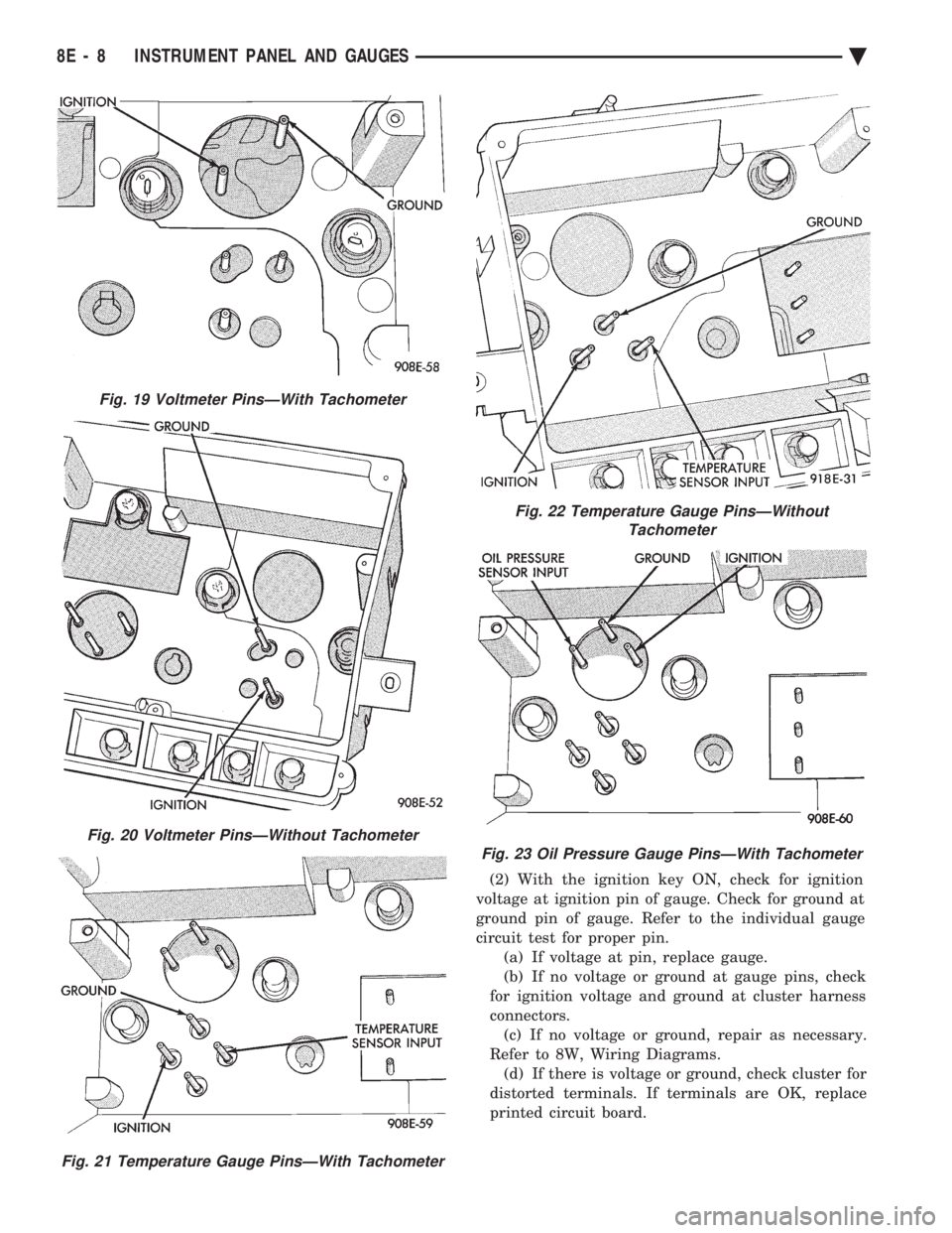
(2) With the ignition key ON, check for ignition
voltage at ignition pin of gauge. Check for ground at
ground pin of gauge. Refer to the individual gauge
circuit test for proper pin. (a) If voltage at pin, replace gauge.
(b) If no voltage or ground at gauge pins, check
for ignition voltage and ground at cluster harness
connectors. (c) If no voltage or ground, repair as necessary.
Refer to 8W, Wiring Diagrams. (d) If there is voltage or ground, check cluster for
distorted terminals. If terminals are OK, replace
printed circuit board.
Fig. 19 Voltmeter PinsÐWith Tachometer
Fig. 20 Voltmeter PinsÐWithout Tachometer
Fig. 21 Temperature Gauge PinsÐWith Tachometer
Fig. 22 Temperature Gauge PinsÐWithout Tachometer
Fig. 23 Oil Pressure Gauge PinsÐWith Tachometer
8E - 8 INSTRUMENT PANEL AND GAUGES Ä
Page 501 of 2438

(3) When testing temperature, allow the engine to
run until the vehicle reaches a normal operating
temperature. Turn ignition OFF, and remove gauge
from cluster. (a) Testing oil pressure gauge, engine needs to
be running. (b) Measure and record the resistance between
sending unit pin and ground pin of the gauge in
question. Refer to Gauge Calibration. (c) It is important to have the same engine tem-
perature and engine speed when checking temper-
ature and oil pressure gauges position. The time
between gauge position reading and sending unit
measuring should be kept to a minimum. (d) If resistance and gauge position are not sim-
ilar, replace gauge. (e) If OK, test resistance from the sending unit
to the cluster connector. (f) If resistance reading is different, check
printed circuit board for contact to cluster connec-
tor. (g) If OK and contacts are not distorted, replace
printed circuit board. (h) If everything checks out OK, refer to sending
unit test.
(4) If fuel gauge does not meet specifications, refer
to Group 14, Fuel for the test procedure.
GAUGE CALIBRATION
(1) Remove the gauge.
(2) Check for ignition voltage and ground to the
gauge. (3) With the ignition key in the OFF position, re-
place gauge. Turn the ignition key to the ON posi-
tion. To test oil pressure gauge engine must be
running. When testing oil or temperature gauge the
engine should be at normal operating temperature.
Record the gauge position. (4) Remove gauge and record the resistance be-
tween the sending unit pin and the gauge ground
pin. When checking gauges, it is important to have
the same engine temperature and speed when noting
gauge position. The time between gauge reading and
measuring should be kept to a minimum. (5) The Gauge Resistance Chart (Fig. 24), is gen-
eral guidelines for checking the gauge position
against the sending unit resistance. Because of only a few specific points of gauge posi-
tion versus sending unit resistance, a good estimate
is need when the resistance falls between gradua-
tions. Even when the resistance corresponds to grad-
uations, the gauge has a tolerance of 64 ohms.
Volt gauge: The calibration dot on the volt gauge
corresponds to 13 volts between the gauge ignition
and ground pins. If voltage varies from this, estimate
proper gauge position with input voltage.
TACHOMETER REPLACEMENT
(1) Remove cluster, radio and rear window defog-
ger bezels and mask/lens assembly. (2) Remove screws attaching tachometer to cluster
housing. (3) Pull tachometer rearward to remove.
(4) For installation reverse above procedures.
TACHOMETER CIRCUIT TESTING
(1) Remove cluster, radio and rear window defog-
ger bezels and mask/lens assembly. (2) Check for battery voltage at cavity A of the in-
strument cluster black connector. (3) With the ignition in the ON position, check for
battery voltage at cavity C of the black connector
(Fig. 25).
Fig. 24 Gauge Resistance
Fig. 25 Printed Circuit Board 11-Way Connector
Ä INSTRUMENT PANEL AND GAUGES 8E - 9
Page 502 of 2438
(4) Check cavity H of the black connector for con-
tinuity to ground. (5) Check for tachometer signal from the power-
train control module by connecting an AC DIGITAL
VOLTMETER to cavity B of the instrument cluster
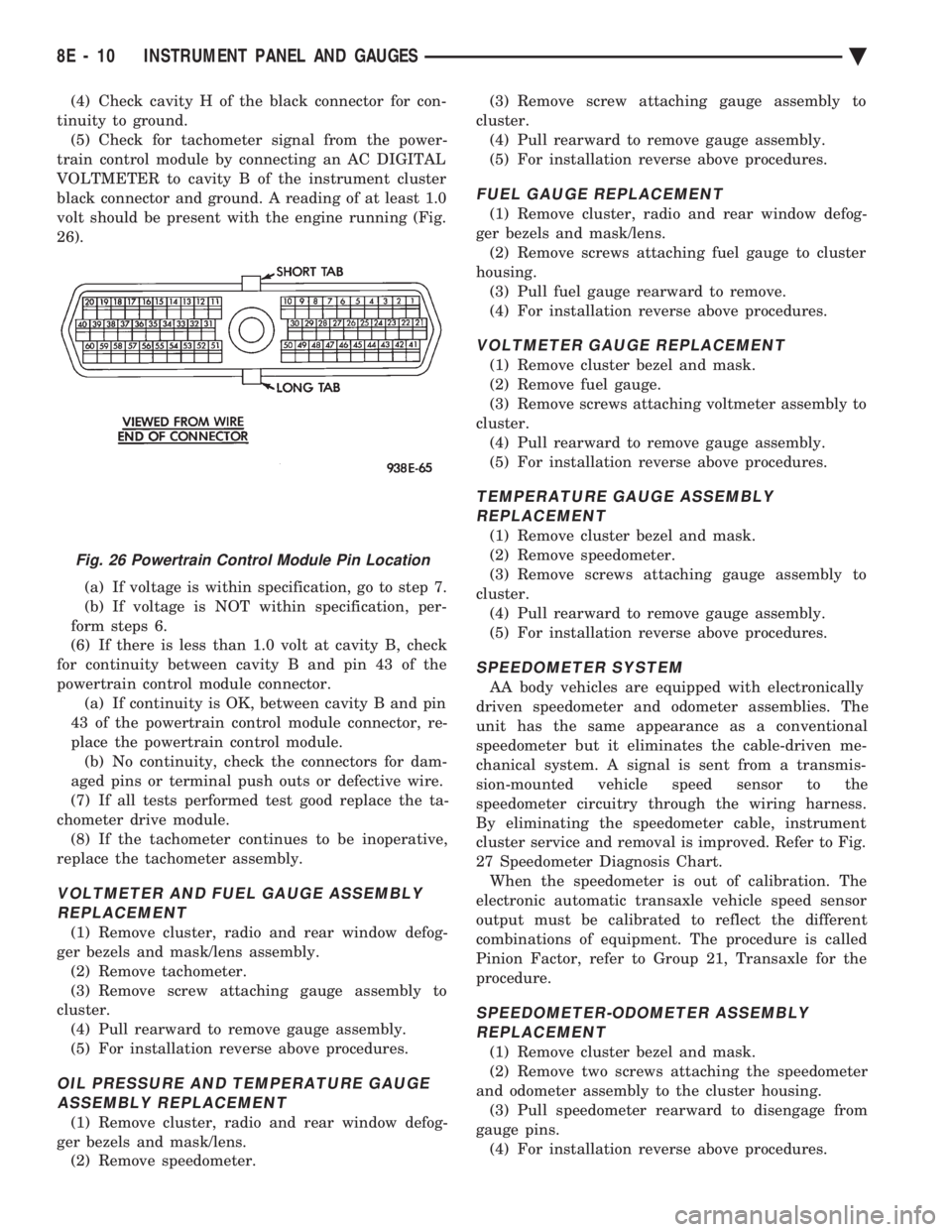
black connector and ground. A reading of at least 1.0
volt should be present with the engine running (Fig.
26).
(a) If voltage is within specification, go to step 7.
(b) If voltage is NOT within specification, per-
form steps 6.
(6) If there is less than 1.0 volt at cavity B, check
for continuity between cavity B and pin 43 of the
powertrain control module connector. (a) If continuity is OK, between cavity B and pin
43 of the powertrain control module connector, re-
place the powertrain control module. (b) No continuity, check the connectors for dam-
aged pins or terminal push outs or defective wire.
(7) If all tests performed test good replace the ta-
chometer drive module. (8) If the tachometer continues to be inoperative,
replace the tachometer assembly.
VOLTMETER AND FUEL GAUGE ASSEMBLY REPLACEMENT
(1) Remove cluster, radio and rear window defog-
ger bezels and mask/lens assembly. (2) Remove tachometer.
(3) Remove screw attaching gauge assembly to
cluster. (4) Pull rearward to remove gauge assembly.
(5) For installation reverse above procedures.
OIL PRESSURE AND TEMPERATURE GAUGEASSEMBLY REPLACEMENT
(1) Remove cluster, radio and rear window defog-
ger bezels and mask/lens. (2) Remove speedometer. (3) Remove screw attaching gauge assembly to
cluster. (4) Pull rearward to remove gauge assembly.
(5) For installation reverse above procedures.
FUEL GAUGE REPLACEMENT
(1) Remove cluster, radio and rear window defog-
ger bezels and mask/lens. (2) Remove screws attaching fuel gauge to cluster
housing. (3) Pull fuel gauge rearward to remove.
(4) For installation reverse above procedures.
VOLTMETER GAUGE REPLACEMENT
(1) Remove cluster bezel and mask.
(2) Remove fuel gauge.
(3) Remove screws attaching voltmeter assembly to
cluster. (4) Pull rearward to remove gauge assembly.
(5) For installation reverse above procedures.
TEMPERATURE GAUGE ASSEMBLY REPLACEMENT
(1) Remove cluster bezel and mask.
(2) Remove speedometer.
(3) Remove screws attaching gauge assembly to
cluster. (4) Pull rearward to remove gauge assembly.
(5) For installation reverse above procedures.
SPEEDOMETER SYSTEM
AA body vehicles are equipped with electronically
driven speedometer and odometer assemblies. The
unit has the same appearance as a conventional
speedometer but it eliminates the cable-driven me-
chanical system. A signal is sent from a transmis-
sion-mounted vehicle speed sensor to the
speedometer circuitry through the wiring harness.
By eliminating the speedometer cable, instrument
cluster service and removal is improved. Refer to Fig.
27 Speedometer Diagnosis Chart. When the speedometer is out of calibration. The
electronic automatic transaxle vehicle speed sensor
output must be calibrated to reflect the different
combinations of equipment. The procedure is called
Pinion Factor, refer to Group 21, Transaxle for the
procedure.
SPEEDOMETER-ODOMETER ASSEMBLY REPLACEMENT
(1) Remove cluster bezel and mask.
(2) Remove two screws attaching the speedometer
and odometer assembly to the cluster housing. (3) Pull speedometer rearward to disengage from
gauge pins. (4) For installation reverse above procedures.
Fig. 26 Powertrain Control Module Pin Location
8E - 10 INSTRUMENT PANEL AND GAUGES Ä
Page 515 of 2438
AC AND AY BODIES INDEX
page page
Electronic Cluster ........................ 34
Gauges ................................ 28
General Information ....................... 23
Interior Lamp Replacement ................. 41 Mechanical Cluster and Gauge Service
........ 24
Mechanical/Electronic Cluster Removal ........ 25
Switch and Panel Component Service ......... 37
GENERAL INFORMATION
MECHANICAL CLUSTER
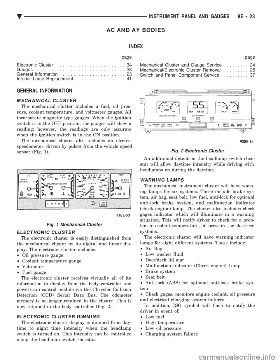
The mechanical cluster includes a fuel, oil pres-
sure, coolant temperature, and voltmeter gauges. All
incorporate magnetic type gauges. When the ignition
switch is in the OFF position, the gauges will show a
reading; however, the readings are only accurate
when the ignition switch is in the ON position. The mechanical cluster also includes an electric
speedometer, driven by pulses from the vehicle speed
sensor (Fig. 1).
ELECTRONIC CLUSTER
The electronic cluster is easily distinguished from
the mechanical cluster by its digital and linear dis-
play. The electronic cluster includes:
² Oil pressure gauge
² Coolant temperature gauge
² Voltmeter
² Fuel gauge
The electronic cluster receives virtually all of its
information to display from the body controller and
powertrain control module via the Chrysler Collision
Detection (CCD) Serial Data Bus. The odometer
memory is no longer retained in the cluster. This is
now retained in the body controller (Fig. 2).
ELECTRONIC CLUSTER DIMMING
The electronic cluster display is dimmed from day-
time to night time intensity when the headlamp
switch is turned on. This intensity can be controlled
using the headlamp switch rheostat. An additional detent on the headlamp switch rheo-
stat will allow daytime intensity while driving with
headlamps on during the daytime.
WARNING LAMPS
The mechanical instrument cluster will have warn-
ing lamps for six systems. These include brake sys-
tem, air bag, seat belt, low fuel, anti-lock for optional
anti-lock brake system, and malfunction indicator
(check engine) lamp. The cluster also includes check
gages indicator which will illuminate in a warning
situation. This will notify driver to check for a prob-
lem in coolant temperature, oil pressure, or electrical
systems. The electronic cluster will have warning indicator
lamps for eight different systems. These include:
² Air Bag
² Low washer fluid
² Door/deck lid ajar
² Malfunction Indicator (Check engine) Lamp
² Brake system
² Seat belt
² Anti-lock (ABS) for optional anti-lock brake sys-
tem
² Check gages, monitors engine coolant, oil pressure
and electrical charging system failures. In addition, ISO symbol will flash to notify the
driver in event of:
² Low fuel
² High temperature
² Low oil pressure
² Charging system failure
Fig. 1 Mechanical Cluster
Fig. 2 Electronic Cluster
Ä INSTRUMENT PANEL AND GAUGES 8E - 23
Page 516 of 2438

MESSAGE CENTER
The message center is a car graphic warning lamp
module. This conventional warning system and lo-
cated above the headlamp switch.
ELECTRONIC DIGITAL CLOCK
The electronic digital clock is in the radio. The
clock and radio each use the display panel built into
the radio. A digital readout indicates the time in
hours and minutes whenever the ignition switch is in
the ON or ACC position. When the ignition switch is in the OFF position, or
when the radio frequency is being displayed, time
keeping is accurately maintained. The procedure for setting the clock varies slightly
with each radio. The correct procedure is described
under the individual radio operating instructions re-
ferred to in the Owner's Manual supplied with the
vehicle.
AIR BAG WARNING SYSTEM
For testing of this system refer to Group 8M, Re-
straint Systems.
MECHANICAL CLUSTER AND GAUGE SERVICE
CAUTION: Disconnect negative battery cable, in en-
gine compartment, before servicing instrument
panel. When power is required for test purposes,
reconnect battery cable for the test only.
Disconnect negative battery cable after test and be-
fore continuing service procedures.
SENDING UNIT TEST
When a problem occurs with a cluster gauge, be-
fore disassembling the cluster to check the gauge,
check for a defective sending unit or wiring. (1) Sending units and wiring can be checked by
grounding the connector leads, at the sending unit,
in the vehicle. (2) With the ignition in the ON position; a
grounded input will cause the oil, fuel or tempera-
ture gauge to read at or above maximum.
CHECK GAUGES WARNING LAMP TESTS
The check gauges warning lamp is illuminated by
the low oil pressure sending unit switch or the body
controller when there is high temperature or charg-
ing system failure. To test the lamp, turn ignition key to the ON po-
sition without starting the vehicle. The low oil pres-
sure switch is grounded and the light will be on
indefinitely. If the lamp fails to light, pull the cluster and check
the following: (a) Continuity between ground and check gauge
pin J (Fig. 3). (b) Proper contact between the gauge pins and
wiring harness and printed circuit board pins. (c) If there is ground and proper pin contact, re-
place lamp. (d) If there is no continuity, check the low oil
pressure sending unit switch (Fig. 4 and 5).
To test the switch disconnect the switch electrical
connector. Attach positive lead of an ohmmeter to
the switch terminal for the gray (GY) wire and the
negative lead to an engine ground. With the engine
Fig. 3 Mechanical Cluster Connectors
8E - 24 INSTRUMENT PANEL AND GAUGES Ä
Page 521 of 2438

(c) If there is voltage or ground, check cluster for
distorted terminals. If terminals are OK, replace
printed circuit board.
(3) When testing temperature and oil pressure
gauges allow the engine to run until the vehicle
reaches a normal operating temperature. Turn igni-
tion OFF, and remove gauge from cluster. (a) Testing oil pressure gauge, engine needs to
be running. (b) Measure and record the resistance between
sending unit pin and ground pin of the gauge in
question. Refer to Gauge Calibration. (c) When checking temperature and oil pressure
gauges, it is important to have the same engine
temperature and speed when noting gauge position.
The time between gauge reading and measuring
should be kept to a minimum. (d) If resistance and gauge position are not sim-
ilar, replace gauge. (e) If OK, test resistance from the sending unit
to the cluster connector. (f) If resistance reading is different, check
printed circuit board for contact to cluster. (g) If OK and contacts are not distorted, replace
printed circuit board. (h) If everything checks out OK, refer to Sending
Unit Test.
(4) If fuel gauge meets specifications check fuel
tank and original fuel tank sending unit as follow: (a) Carefully remove fuel tank sending unit from
tank.
Fig. 16 Printed Circuit Board
Fig. 17 Fuel Gauge Pins
Fig. 18 Voltmeter Pins
Fig. 19 Temperature Gauge Pins
Fig. 20 Oil Pressure Gauge Pins
Ä INSTRUMENT PANEL AND GAUGES 8E - 29
Page 522 of 2438
(b) Refer to sending unit removal Group 14, Fuel.
(c) Connect sending unit wire and jumper wire
as described in the test procedure.
(5) If fuel gauge now checks within specifications,
original sending unit is electrically okay, check fol-
lowing as a possible cause: (a) Ground wire from sending unit to left side
cowl for continuity. (b) Sending unit deformed. Make sure sending
unit float arm moves freely and pick up tube is not
bent upwards creating an interference with bottom
of tank and inspect float. (c) Sending unit improperly installed. Install
properly. (d) Mounting flange on fuel tank for sending
unit deformed. Feel for interference fit of sending
unit to bottom of tank. It is permissible to bend
pick up tube down a little near mounting flange to
gain interference fit. (e) Fuel tank bottom deformed, causing improper
positioning of sending unit pick up tube. Replace or
repair tank and recheck sending unit.
GAUGE CALIBRATION
(1) Remove the gauge.
(2) Check for ignition voltage and ground to the
gauge. (3) With the ignition key in the OFF position, re-
place gauge. Turn the ignition key to the ON posi-
tion. To test oil pressure gauge engine must be
running. When testing oil or temperature gauge the
engine should be at normal operating temperature.
Record the gauge position. (4) Remove gauge and record the resistance be-
tween the sending unit pin and the gauge ground
pin. When checking gauges, it is important to have
the same engine temperature and speed when noting
gauge position. The time between gauge reading and
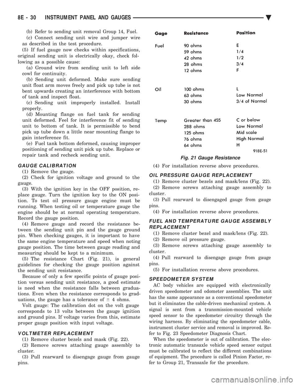
measuring should be kept to a minimum. (5) The resistance Chart (Fig. 21), is general
guidelines for checking the gauge position against
the sending unit resistance. Because of only a few specific points of gauge posi-
tion versus sending unit resistance, a good estimate
is need when the resistance falls between gradua-
tions. Even when the resistance corresponds to grad-
uations, the gauge has a tolerance of 64 ohms.
Volt gauge: The calibration dot on the volt gauge
corresponds to 13 volts between the gauge ignition
and ground pins. If voltage varies from this, estimate
proper gauge position with input voltage.
VOLTMETER REPLACEMENT
(1) Remove cluster bezels and mask (Fig. 22).
(2) Remove screws attaching gauge assembly to
cluster. (3) Pull rearward to disengage gauge from gauge
pins. (4) For installation reverse above procedures.
OIL PRESSURE GAUGE REPLACEMENT
(1) Remove cluster bezels and mask/lens (Fig. 22).
(2) Remove screws attaching gauge assembly to
cluster.
(3) Pull rearward to disengaged gauge from gauge
pins.
(4) For installation reverse above procedures.
FUEL AND TEMPERATURE GAUGE ASSEMBLY REPLACEMENT
(1) Remove cluster bezel and mask/lens (Fig. 22).
(2) Remove oil pressure gauge.
(3) Remove screws attaching gauge assembly to
cluster.
(4) Pull rearward to disengage gauge from gauge
pins.
(5) For installation reverse above procedures.
SPEEDOMETER SYSTEM
AC body vehicles are equipped with electronically
driven speedometer and odometer assemblies. The unit
has the same appearance as a conventional speedometer
but it eliminates the cable-driven mechanical system. A
signal is sent from a transmission-mounted vehicle
speed sensor to the speedometer circuitry through the
wiring harness. By eliminating the speedometer cable,
instrument cluster service and removal is improved. Re-
fer to Fig. 23 Speedometer Diagnosis Chart. When the speedometer is out of calibration. The elec-
tronic automatic transaxle vehicle speed sensor output
must be calibrated to reflect the different combinations
of equipment. The procedure is called Pinion Factor, re-
fer to Group 21, Transaxle for the procedure.
Fig. 21 Gauge Resistance
8E - 30 INSTRUMENT PANEL AND GAUGES Ä
Page 534 of 2438
AG AND AJ BODIES INDEX
page page
Cigar Lighter Removal ..................... 55
Cluster and Gauge Service and Testing ....... 43
Electronic Cluster ........................ 50
Electronic Vehicle Information Center (EVIC) .... 42
Engine Compartment Node ................. 55
Gauges ................................ 44 General Information
....................... 42
Instrument Panel Roll Down Procedure ........ 56
Interior Lamp Removal .................... 57
Mechanical/Electronic Cluster Removal ........ 43
Switch and Panel Component Service ......... 51
Switch Pod Assembly Removal .............. 43
GENERAL INFORMATION
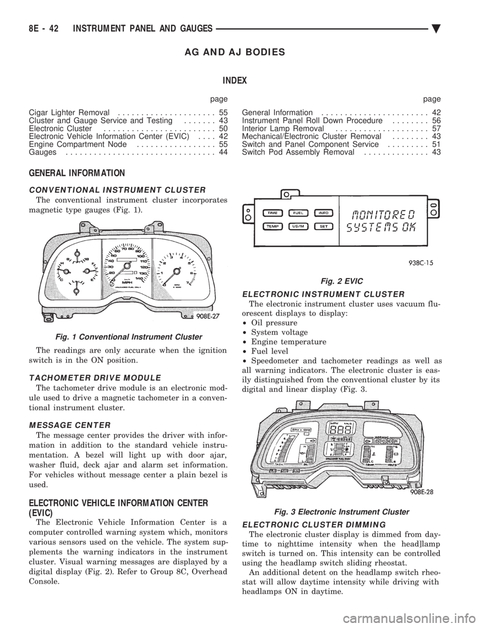
CONVENTIONAL INSTRUMENT CLUSTER
The conventional instrument cluster incorporates
magnetic type gauges (Fig. 1).
The readings are only accurate when the ignition
switch is in the ON position.
TACHOMETER DRIVE MODULE
The tachometer drive module is an electronic mod-
ule used to drive a magnetic tachometer in a conven-
tional instrument cluster.
MESSAGE CENTER
The message center provides the driver with infor-
mation in addition to the standard vehicle instru-
mentation. A bezel will light up with door ajar,
washer fluid, deck ajar and alarm set information.
For vehicles without message center a plain bezel is
used.
ELECTRONIC VEHICLE INFORMATION CENTER
(EVIC)
The Electronic Vehicle Information Center is a
computer controlled warning system which, monitors
various sensors used on the vehicle. The system sup-
plements the warning indicators in the instrument
cluster. Visual warning messages are displayed by a
digital display (Fig. 2). Refer to Group 8C, Overhead
Console.
ELECTRONIC INSTRUMENT CLUSTER
The electronic instrument cluster uses vacuum flu-
orescent displays to display:
² Oil pressure
² System voltage
² Engine temperature
² Fuel level
² Speedometer and tachometer readings as well as
all warning indicators. The electronic cluster is eas-
ily distinguished from the conventional cluster by its
digital and linear display (Fig. 3.
ELECTRONIC CLUSTER DIMMING
The electronic cluster display is dimmed from day-
time to nighttime intensity when the head]lamp
switch is turned on. This intensity can be controlled
using the headlamp switch sliding rheostat. An additional detent on the headlamp switch rheo-
stat will allow daytime intensity while driving with
headlamps ON in daytime.
Fig. 1 Conventional Instrument Cluster
Fig. 2 EVIC
Fig. 3 Electronic Instrument Cluster
8E - 42 INSTRUMENT PANEL AND GAUGES Ä