1993 CHEVROLET PLYMOUTH ACCLAIM height
[x] Cancel search: heightPage 1991 of 2438
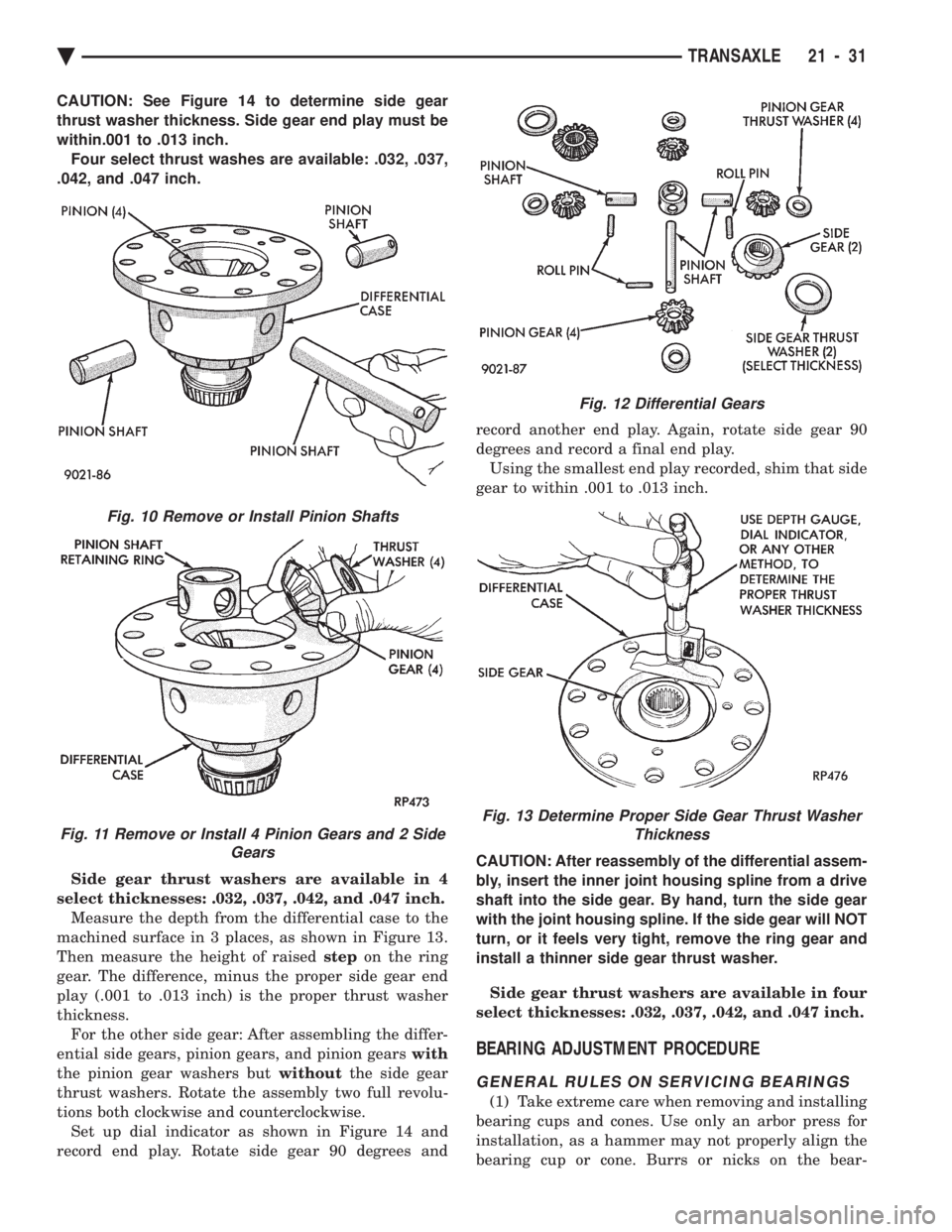
CAUTION: See Figure 14 to determine side gear
thrust washer thickness. Side gear end play must be
within.001 to .013 inch.Four select thrust washes are available: .032, .037,
.042, and .047 inch.
Side gear thrust washers are available in 4
select thicknesses: .032, .037, .042, and .047 inch. Measure the depth from the differential case to the
machined surface in 3 places, as shown in Figure 13.
Then measure the height of raised stepon the ring
gear. The difference, minus the proper side gear end
play (.001 to .013 inch) is the proper thrust washer
thickness. For the other side gear: After assembling the differ-
ential side gears, pinion gears, and pinion gears with
the pinion gear washers but withoutthe side gear
thrust washers. Rotate the assembly two full revolu-
tions both clockwise and counterclockwise. Set up dial indicator as shown in Figure 14 and
record end play. Rotate side gear 90 degrees and record another end play. Again, rotate side gear 90
degrees and record a final end play.
Using the smallest end play recorded, shim that side
gear to within .001 to .013 inch.
CAUTION: After reassembly of the differential assem-
bly, insert the inner joint housing spline from a drive
shaft into the side gear. By hand, turn the side gear
with the joint housing spline. If the side gear will NOT
turn, or it feels very tight, remove the ring gear and
install a thinner side gear thrust washer.
Side gear thrust washers are available in four
select thicknesses: .032, .037, .042, and .047 inch.
BEARING ADJUSTMENT PROCEDURE
GENERAL RULES ON SERVICING BEARINGS
(1) Take extreme care when removing and installing
bearing cups and cones. Use only an arbor press for
installation, as a hammer may not properly align the
bearing cup or cone. Burrs or nicks on the bear-
Fig. 12 Differential Gears
Fig. 13 Determine Proper Side Gear Thrust Washer Thickness
Fig. 10 Remove or Install Pinion Shafts
Fig. 11 Remove or Install 4 Pinion Gears and 2 Side Gears
Ä TRANSAXLE 21 - 31
Page 2162 of 2438
POWER SUNROOF INDEX
page page
Adjustment Bracket ........................ 7
Drain Channel ............................ 7
Drive Cable Locators ....................... 7
Drive Cables ............................. 8
General Information ........................ 6
Glass Panel ............................. 7 Glass Vertical Height Adjustment
.............. 6
Guide Assembly .......................... 8
Motor and Drive Gears ..................... 7
Sunshade ............................... 8
Wind Deflector ........................... 6
GENERAL INFORMATION
All sunroofs are equipped with drain tubes that are
located in the A, B or C-pillars. The drain tubes
must be kept open to prevent water from entering
the passenger compartment.
LUBRICATION
(1) Lubricate cables with Lubriplate or equivalent
when cables are replaced. (2) Periodically clean dirt from guide rail covers.
DRAIN TUBES
² Inspect the drain holes, located in the trough
around the sunroof opening to verify they are clear.
Inspection should be performed at least once a year
or when problems are suspected. If drain hose or
tubes are plugged, use compressed air or blunt flexi-
ble wire to clear them. If tubes cannot be cleared,
they must be repaired.
² The lower ends of the rear drain tubes are located
in the rear quarter panel drop wells. To clear rear
drain tubes, use compressed air or blunt flexible wire
from the lower ends of the tubes.
GLASS VERTICAL HEIGHT ADJUSTMENT
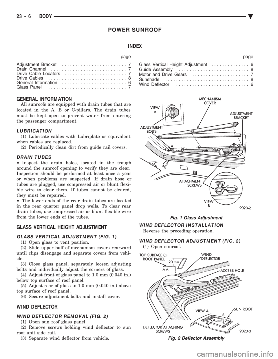
GLASS VERTICAL ADJUSTMENT (FIG. 1)
(1) Open glass to vent position.
(2) Slide upper half of mechanism covers rearward
until clips disengage and separate covers from vehi-
cle. (3) Close glass panel, separately loosen adjusting
bolts and individually adjust the corners of glass. (4) Adjust front of glass panel to 1.0 mm (0.040 in.)
below top surface of roof panel. (5) Adjust rear of glass to 1.0 mm (0.040 in.) above
top surface of roof panel. (6) Secure adjustment bolts and install cover.
WIND DEFLECTOR
WIND DEFLECTOR REMOVAL (FIG. 2)
(1) Open sun roof glass panel.
(2) Remove screws holding wind deflector to sun
roof unit side rail. (3) Separate wind deflector from vehicle.
WIND DEFLECTOR INSTALLATION
Reverse the preceding operation.
WIND DEFLECTOR ADJUSTMENT (FIG. 2)
(1) Open sunroof.
Fig. 1 Glass Adjustment
Fig. 2 Deflector Assembly
23 - 6 BODY Ä
Page 2163 of 2438
(2) position wind deflector so 19 mm (0.75 in.)
above top surface of roof panel and 1 mm (0.040 in.)
rearward of roof panel forward edge. (3) Secure wind deflector to sunroof unit.
GLASS PANEL
GLASS PANEL REMOVAL
(1) Remove wind deflector mechanism covers (Fig.
1). (2) Position glass to vent position.
(3) Position sunshade full rearward.
(4) Loosen nuts holding glass panel to side adjust-
ment brackets. (5) Slide glass panel rearward 12 mm (0.5 in.) and
separate glass from sunroof unit.
GLASS PANEL INSTALLATION
(1) Position glass panel in opening with logo rear-
ward and slide panel forward 12 mm (0.5 in.). (2) Verify that attaching nuts are below top sur-
face of glass adjustment brackets. (3) Close sunroof to center glass panel in roof open-
ing. (4) Tighten center screws to hold adjustment.
(5) Open glass to vent position and tighten nuts to
8N Im (70.8 in-lbs.).
(6) Close glass and check alignment.
(7) Install the mechanism covers.
(8) Adjust wind deflector, if necessary.
ADJUSTMENT BRACKET
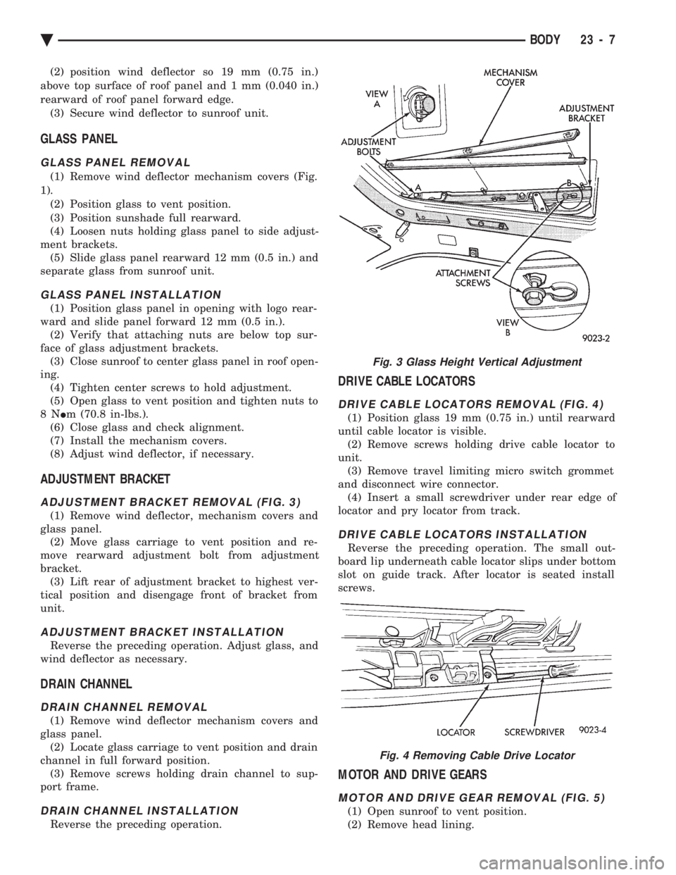
ADJUSTMENT BRACKET REMOVAL (FIG. 3)
(1) Remove wind deflector, mechanism covers and
glass panel. (2) Move glass carriage to vent position and re-
move rearward adjustment bolt from adjustment
bracket. (3) Lift rear of adjustment bracket to highest ver-
tical position and disengage front of bracket from
unit.
ADJUSTMENT BRACKET INSTALLATION
Reverse the preceding operation. Adjust glass, and
wind deflector as necessary.
DRAIN CHANNEL
DRAIN CHANNEL REMOVAL
(1) Remove wind deflector mechanism covers and
glass panel. (2) Locate glass carriage to vent position and drain
channel in full forward position. (3) Remove screws holding drain channel to sup-
port frame.
DRAIN CHANNEL INSTALLATION
Reverse the preceding operation.
DRIVE CABLE LOCATORS
DRIVE CABLE LOCATORS REMOVAL (FIG. 4)
(1) Position glass 19 mm (0.75 in.) until rearward
until cable locator is visible. (2) Remove screws holding drive cable locator to
unit. (3) Remove travel limiting micro switch grommet
and disconnect wire connector. (4) Insert a small screwdriver under rear edge of
locator and pry locator from track.
DRIVE CABLE LOCATORS INSTALLATION
Reverse the preceding operation. The small out-
board lip underneath cable locator slips under bottom
slot on guide track. After locator is seated install
screws.
MOTOR AND DRIVE GEARS
MOTOR AND DRIVE GEAR REMOVAL (FIG. 5)
(1) Open sunroof to vent position.
(2) Remove head lining.
Fig. 3 Glass Height Vertical Adjustment
Fig. 4 Removing Cable Drive Locator
Ä BODY 23 - 7
Page 2168 of 2438
(5) With assistance of a helper at the opposite side
of the vehicle to support the hood, remove the bottom
hood to hinge attaching bolts. Separate the hood
from the vehicle.
HOOD INSTALLATION
Reverse the preceding operation.
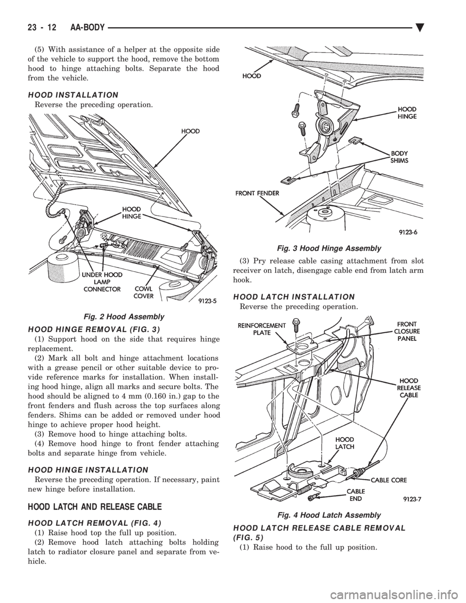
HOOD HINGE REMOVAL (FIG. 3)
(1) Support hood on the side that requires hinge
replacement. (2) Mark all bolt and hinge attachment locations
with a grease pencil or other suitable device to pro-
vide reference marks for installation. When install-
ing hood hinge, align all marks and secure bolts. The
hood should be aligned to 4 mm (0.160 in.) gap to the
front fenders and flush across the top surfaces along
fenders. Shims can be added or removed under hood
hinge to achieve proper hood height. (3) Remove hood to hinge attaching bolts.
(4) Remove hood hinge to front fender attaching
bolts and separate hinge from vehicle.
HOOD HINGE INSTALLATION
Reverse the preceding operation. If necessary, paint
new hinge before installation.
HOOD LATCH AND RELEASE CABLE
HOOD LATCH REMOVAL (FIG. 4)
(1) Raise hood top the full up position.
(2) Remove hood latch attaching bolts holding
latch to radiator closure panel and separate from ve-
hicle. (3) Pry release cable casing attachment from slot
receiver on latch, disengage cable end from latch arm
hook.
HOOD LATCH INSTALLATION
Reverse the preceding operation.
HOOD LATCH RELEASE CABLE REMOVAL (FIG. 5)
(1) Raise hood to the full up position.
Fig. 2 Hood Assembly
Fig. 3 Hood Hinge Assembly
Fig. 4 Hood Latch Assembly
23 - 12 AA-BODY Ä
Page 2195 of 2438
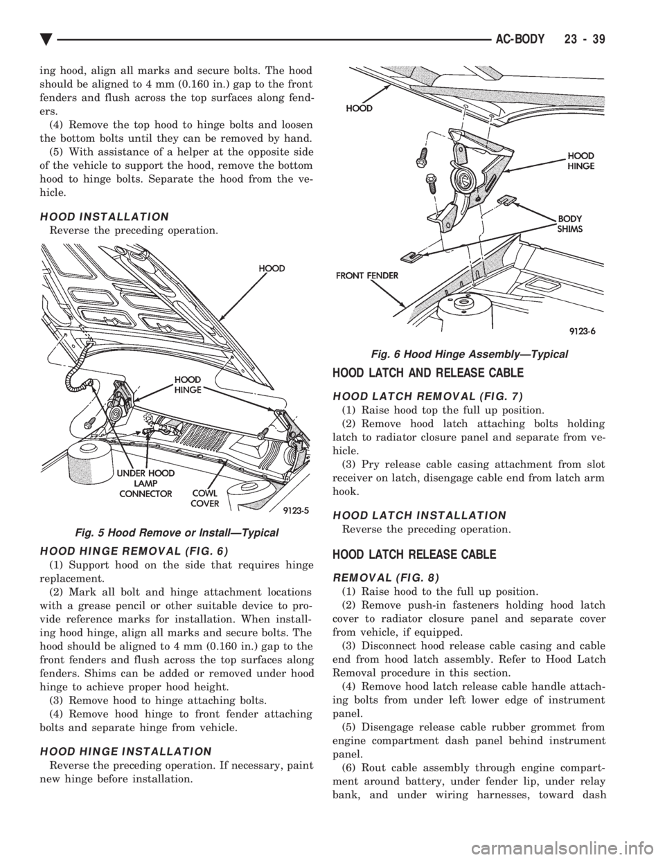
ing hood, align all marks and secure bolts. The hood
should be aligned to 4 mm (0.160 in.) gap to the front
fenders and flush across the top surfaces along fend-
ers.(4) Remove the top hood to hinge bolts and loosen
the bottom bolts until they can be removed by hand. (5) With assistance of a helper at the opposite side
of the vehicle to support the hood, remove the bottom
hood to hinge bolts. Separate the hood from the ve-
hicle.
HOOD INSTALLATION
Reverse the preceding operation.
HOOD HINGE REMOVAL (FIG. 6)
(1) Support hood on the side that requires hinge
replacement. (2) Mark all bolt and hinge attachment locations
with a grease pencil or other suitable device to pro-
vide reference marks for installation. When install-
ing hood hinge, align all marks and secure bolts. The
hood should be aligned to 4 mm (0.160 in.) gap to the
front fenders and flush across the top surfaces along
fenders. Shims can be added or removed under hood
hinge to achieve proper hood height. (3) Remove hood to hinge attaching bolts.
(4) Remove hood hinge to front fender attaching
bolts and separate hinge from vehicle.
HOOD HINGE INSTALLATION
Reverse the preceding operation. If necessary, paint
new hinge before installation.
HOOD LATCH AND RELEASE CABLE
HOOD LATCH REMOVAL (FIG. 7)
(1) Raise hood top the full up position.
(2) Remove hood latch attaching bolts holding
latch to radiator closure panel and separate from ve-
hicle. (3) Pry release cable casing attachment from slot
receiver on latch, disengage cable end from latch arm
hook.
HOOD LATCH INSTALLATION
Reverse the preceding operation.
HOOD LATCH RELEASE CABLE
REMOVAL (FIG. 8)
(1) Raise hood to the full up position.
(2) Remove push-in fasteners holding hood latch
cover to radiator closure panel and separate cover
from vehicle, if equipped. (3) Disconnect hood release cable casing and cable
end from hood latch assembly. Refer to Hood Latch
Removal procedure in this section. (4) Remove hood latch release cable handle attach-
ing bolts from under left lower edge of instrument
panel. (5) Disengage release cable rubber grommet from
engine compartment dash panel behind instrument
panel. (6) Rout cable assembly through engine compart-
ment around battery, under fender lip, under relay
bank, and under wiring harnesses, toward dash
Fig. 5 Hood Remove or InstallÐTypical
Fig. 6 Hood Hinge AssemblyÐTypical
Ä AC-BODY 23 - 39
Page 2209 of 2438
HOOD INSTALLATION
Reverse the preceding operation.
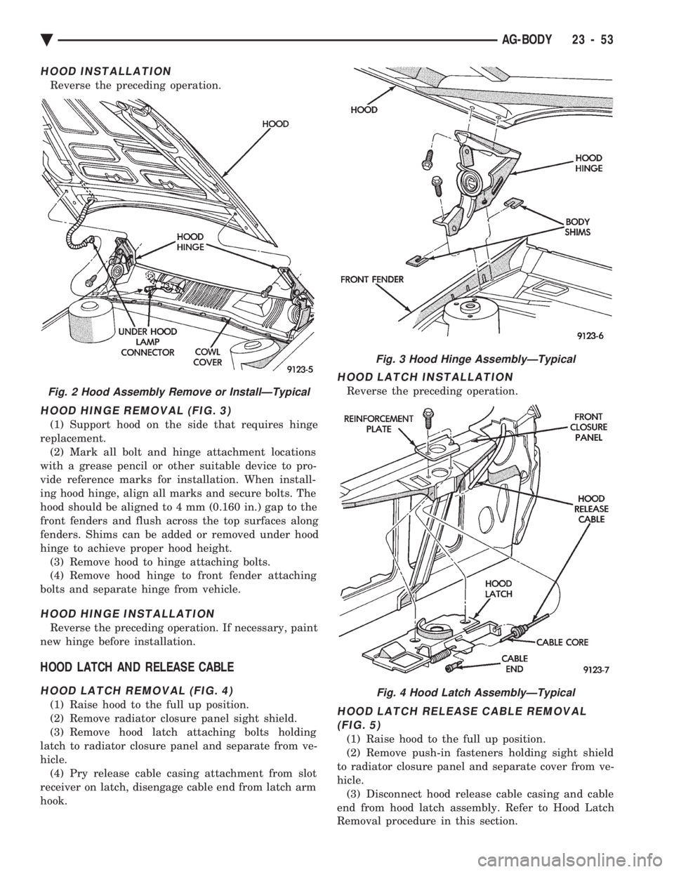
HOOD HINGE REMOVAL (FIG. 3)
(1) Support hood on the side that requires hinge
replacement. (2) Mark all bolt and hinge attachment locations
with a grease pencil or other suitable device to pro-
vide reference marks for installation. When install-
ing hood hinge, align all marks and secure bolts. The
hood should be aligned to 4 mm (0.160 in.) gap to the
front fenders and flush across the top surfaces along
fenders. Shims can be added or removed under hood
hinge to achieve proper hood height. (3) Remove hood to hinge attaching bolts.
(4) Remove hood hinge to front fender attaching
bolts and separate hinge from vehicle.
HOOD HINGE INSTALLATION
Reverse the preceding operation. If necessary, paint
new hinge before installation.
HOOD LATCH AND RELEASE CABLE
HOOD LATCH REMOVAL (FIG. 4)
(1) Raise hood to the full up position.
(2) Remove radiator closure panel sight shield.
(3) Remove hood latch attaching bolts holding
latch to radiator closure panel and separate from ve-
hicle. (4) Pry release cable casing attachment from slot
receiver on latch, disengage cable end from latch arm
hook.
HOOD LATCH INSTALLATION
Reverse the preceding operation.
HOOD LATCH RELEASE CABLE REMOVAL (FIG. 5)
(1) Raise hood to the full up position.
(2) Remove push-in fasteners holding sight shield
to radiator closure panel and separate cover from ve-
hicle. (3) Disconnect hood release cable casing and cable
end from hood latch assembly. Refer to Hood Latch
Removal procedure in this section.
Fig. 2 Hood Assembly Remove or InstallÐTypical
Fig. 3 Hood Hinge AssemblyÐTypical
Fig. 4 Hood Latch AssemblyÐTypical
Ä AG-BODY 23 - 53
Page 2228 of 2438
(6) Remove nuts holding grille opening panel to
front fenders. (7) Remove bolts holding grille opening panel to
front fenders. (8) Separate grille opening panel form vehicle.
INSTALLATION
Reverse the preceding operation. Align grille open-
ing panel to fit flush across fender joining locations.
HOOD AND HINGES
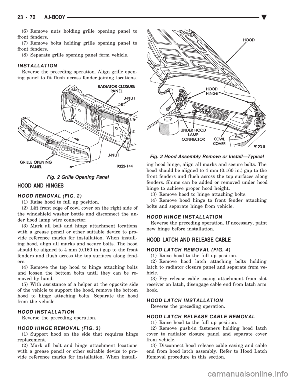
HOOD REMOVAL (FIG. 2)
(1) Raise hood to full up position.
(2) Lift front edge of cowl cover on the right side of
the windshield washer bottle and disconnect the un-
der hood lamp wire connector. (3) Mark all bolt and hinge attachment locations
with a grease pencil or other suitable device to pro-
vide reference marks for installation. When install-
ing hood, align all marks and secure bolts. The hood
should be aligned to 4 mm (0.160 in.) gap to the front
fenders and flush across the top surfaces along fend-
ers. (4) Remove the top hood to hinge attaching bolts
and loosen the bottom bolts until they can be re-
moved by hand. (5) With assistance of a helper at the opposite side
of the vehicle to support the hood, remove the bottom
hood to hinge attaching bolts. Separate the hood
from the vehicle.
HOOD INSTALLATION
Reverse the preceding operation.
HOOD HINGE REMOVAL (FIG. 3)
(1) Support hood on the side that requires hinge
replacement. (2) Mark all bolt and hinge attachment locations
with a grease pencil or other suitable device to pro-
vide reference marks for installation. When install- ing hood hinge, align all marks and secure bolts. The
hood should be aligned to 4 mm (0.160 in.) gap to the
front fenders and flush across the top surfaces along
fenders. Shims can be added or removed under hood
hinge to achieve proper hood height. (3) Remove hood to hinge attaching bolts.
(4) Remove hood hinge to front fender attaching
bolts and separate hinge from vehicle.
HOOD HINGE INSTALLATION
Reverse the preceding operation. If necessary, paint
new hinge before installation.
HOOD LATCH AND RELEASE CABLE
HOOD LATCH REMOVAL (FIG. 4)
(1) Raise hood to the full up position.
(2) Remove hood latch attaching bolts holding
latch to radiator closure panel and separate from ve-
hicle. (3) Pry release cable casing attachment from slot
receiver on latch, disengage cable end from latch arm
hook.
HOOD LATCH INSTALLATION
Reverse the preceding operation.
HOOD LATCH RELEASE CABLE REMOVAL
(1) Raise hood to the full up position.
(2) Remove push-in fasteners holding hood latch
cover to radiator closure panel and separate cover
from vehicle. (3) Disconnect hood release cable casing and cable
end from hood latch assembly. Refer to Hood Latch
Removal procedure in this section.
Fig. 2 Grille Opening Panel
Fig. 2 Hood Assembly Remove or InstallÐTypical
23 - 72 AJ-BODY Ä
Page 2254 of 2438
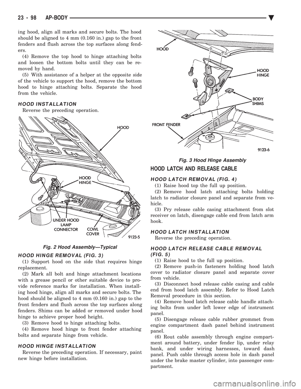
ing hood, align all marks and secure bolts. The hood
should be aligned to 4 mm (0.160 in.) gap to the front
fenders and flush across the top surfaces along fend-
ers.(4) Remove the top hood to hinge attaching bolts
and loosen the bottom bolts until they can be re-
moved by hand. (5) With assistance of a helper at the opposite side
of the vehicle to support the hood, remove the bottom
hood to hinge attaching bolts. Separate the hood
from the vehicle.
HOOD INSTALLATION
Reverse the preceding operation.
HOOD HINGE REMOVAL (FIG. 3)
(1) Support hood on the side that requires hinge
replacement. (2) Mark all bolt and hinge attachment locations
with a grease pencil or other suitable device to pro-
vide reference marks for installation. When install-
ing hood hinge, align all marks and secure bolts. The
hood should be aligned to 4 mm (0.160 in.) gap to the
front fenders and flush across the top surfaces along
fenders. Shims can be added or removed under hood
hinge to achieve proper hood height. (3) Remove hood to hinge attaching bolts.
(4) Remove hood hinge to front fender attaching
bolts and separate hinge from vehicle.
HOOD HINGE INSTALLATION
Reverse the preceding operation. If necessary, paint
new hinge before installation.
HOOD LATCH AND RELEASE CABLE
HOOD LATCH REMOVAL (FIG. 4)
(1) Raise hood top the full up position.
(2) Remove hood latch attaching bolts holding
latch to radiator closure panel and separate from ve-
hicle. (3) Pry release cable casing attachment from slot
receiver on latch, disengage cable end from latch arm
hook.
HOOD LATCH INSTALLATION
Reverse the preceding operation.
HOOD LATCH RELEASE CABLE REMOVAL (FIG. 5)
(1) Raise hood to the full up position.
(2) Remove push-in fasteners holding hood latch
cover to radiator closure panel and separate cover
from vehicle. (3) Disconnect hood release cable casing and cable
end from hood latch assembly. Refer to Hood Latch
Removal procedure in this section. (4) Remove hood latch release cable handle attach-
ing bolts from under left lower edge of instrument
panel. (5) Disengage release cable rubber grommet from
engine compartment dash panel behind instrument
panel. (6) Rout cable assembly through engine compart-
ment around battery, under fender lip, under relay
bank, and under wiring harnesses, toward dash
panel. Push cable through access hole in dash panel
under the brake master cylinder, into passenger com-
partment.
Fig. 2 Hood AssemblyÐTypical
Fig. 3 Hood Hinge Assembly
23 - 98 AP-BODY Ä