1993 CHEVROLET PLYMOUTH ACCLAIM height
[x] Cancel search: heightPage 136 of 2438
(3) Check solenoid to volume canister joint.
² Front strut to solenoid valve connection.
² Rear spring to solenoid valve connection.
(4) Check air line for ruptures, cuts, splits or heat
damage. Use a soap and water solution or a liquid de-
veloped for leak detection.
SYSTEM OPERATION
ENGINE RUN OPERATION
The system will compensate for load
addition/removal when.
² The trunk and all doors are closed.
² The engine speed exceeds 600 R.P.M.
² Throttle angle is less than 65 degrees.
² The brake is not applied.
² You are not cornering above 10 mph.
² There is not a charging system problem with the
vehicle.
ENGINE OFF OPERATION
After passengers/load is removed from the vehicle
the system will correct the vehicle attitude after:
² The trunk and all doors are closed.
² The ignition switch is in the OFF position.
Opening the a door or trunk wakes up the body
computer and the air suspension module. The air
suspension system is now capable of leveling, if
required.
LONG TERM IGNITION OFF OPERATION
The system is capable of one an additional leveling
cycle. After 2 continuous hours of ignition key off and
no door open or trunk open activities. This feature is
implemented to eliminate possible ice freeze-up be-
tween the tire and the inner fender shield.
SYSTEM OPERATION INHIBITORS
The air suspension system is inhibited when:
² The trunk is open.
² A door(s) is/are open.
² The brake pedal is engaged.
² The throttle is at the wide open position.
² The charging system fails.
The maximum compressor pump or exhaust
time is 3 minutes.
SYSTEM FAILURES
Vehicles equipped with air suspension and overhead
console. Will alert the driver of an air suspension
system malfunction. A warning Check Air Suspension
will appear on the overhead console screen.
SAFETY CONCERNS
WARNING: REAR AIR SPRINGS MUST BE DEFLATED
BEFORE BEING REMOVED FROM THE VEHICLE.
WARNING: OPEN TRUNK, OR DOOR(S) OR REMOVE
GROUND STRAP FROM BATTERY BEFORE HOIST-
ING OR JACKING A VEHICLE DURING MECHANICAL
REPAIRS.
WARNING: IF THE VEHICLE NEEDS SERVICE OR
REPAIR OF THE REAR SHOCK ABSORBERS OR
REAR AXLE PIVOT BUSHINGS. THE REAR AIR
SPRINGS MUST HAVE THE AIR PRESSURE RE-
MOVED BEFORE THE VEHICLE CAN BE SERVICED
SAFELY.
SHIPPING MODE
(1) Removing shipping height signal for customer
use.
² Use DRB II tester and 1991 Chassis (Air Suspen-
sion) service cartridge.
² Follow DRB II requirements to cancel shipping
height message in the body computer.
² Connect the Ignition Off Draw (I.O.D.) circuit.
The connection of the IOD circuit will cancel
the Shipping height signal. (2) Return to shipping height.
² Set shipping command in the body computer using
the DRB II and the 1991 Chassis (Air suspension)
service cartridge.
² Disconnect the I.O.D. connector.
DIAGNOSIS
INITIAL DIAGNOSTIC CHECK
(1) Check for blown or missing fuses.
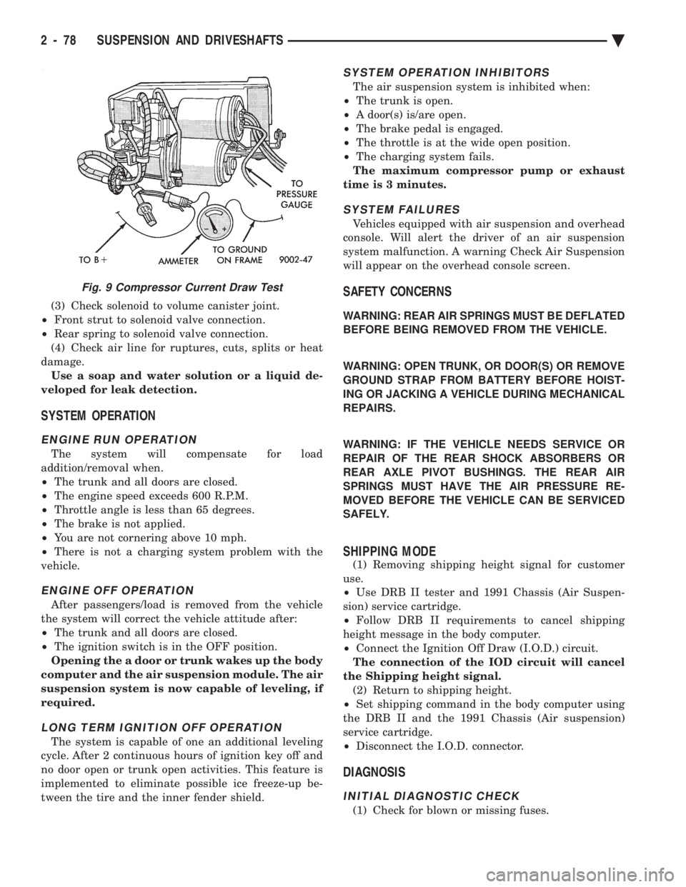
Fig. 9 Compressor Current Draw Test
2 - 78 SUSPENSION AND DRIVESHAFTS Ä
Page 137 of 2438

(2) Check all connectors for correct assembly. Check
all connectors for incorrectly installed termi-
nals. (3) Check pin #21 for minimum of 9.5 volts.
(4) Check pin #20 for minimum of 9.5 volts (with
ignition key on). (5) Check voltage at pins #5 and #16. The measure-
ment should exceed 0 volts. (6) Check pin #19 for continuity.
(7) The engine speed should exceed 680 rpm during
idle. All doors and trunk must be closed for the
system to function.
DIAGNOSTICS PROCEDURES
(1) Use the D.R.B. II tester and the 1991 air suspen-
sion diagnostic service cartridge to begin the trouble-
shooting process. (2) Use the D.R.B. mating connector under the dash
(drivers side) to plug-in the D.R.B. II test connector
(Fig. 10). (3) The tester will conduct a complete check of the
suspension system status. (4) The tester will list the steps to follow to access
and diagnose the failure. (5) A Volt/Ohm meter can be used for some diagnos-
tic testing.
HEIGHT SENSOR CHECK
If a sensor signal/signals are missing. Follow the
repair procedure listed below. (1) Check ground circuit continuity. (Remember
front and rear grounds are on different circuits. (2) For front ground circuit continuity check circuit
S 33. (3) For rear ground circuit continuity check circuit
X20. (4) Refer to control module pin out chart and wiring
diagram (see Group 8F in wiring diagram manual) for
individual circuit details. (5) If open circuits are not found replace the compo-
nent. Complete circuit testing and connector assem-
blies before replacing a strut or right rear shock. (6) To measure resistance values, see Height Sensor
Logic Chart and Initial Diagnostic Check in System
Operation.
HEIGHT SENSOR LOGIC CHART
Ä SUSPENSION AND DRIVESHAFTS 2 - 79
Page 145 of 2438

INSTALL
(1) Inspect O-Ring condition and position on sole-
noid stem. (O-Ring can become dislodged during re-
moval (Fig. 16). (2) Install solenoid with tangs to top ledge of hous-
ing and install retaining clip. (3) Reconnect air line and electrical connection.
STRUT (AIR SUSPENSION) DAMPERASSEMBLY
Service procedures for removal and installation for
(air or steel spring) assemblies are essentially the
same. Except for air venting/recharging and discon-
necting/connecting air lines and electrical connection.
REMOVAL (1) Disconnect battery negative cable.
(2) Hoist vehicle and remove wheel and tire assem-
bly. (3) See AIR LINES AND FITTINGS and discon-
nect air line. (4) Disconnect electrical leads, solenoid and height
sensors. (5) See SOLENOIDS (STRUT AND AIR SPRING)
and vent air spring and remove solenoids. (6) See STRUT DAMPER ASSEMBLY in FRONT
SUSPENSION and remove strut.
DISASSEMBLY/ASSEMBLE Disassembly is restricted to upper mount and bear-
ing housing. The strut shock absorber, air spring
with integral height sensor, solenoid and wiring har-
ness are serviced as an assembly. (1) Hold retaining plate locking washer and re-
move strut rod nut. (2) Remove locking washer, retainer plate, spacer,
flat washer and mount/bearing housing assembly
(Fig. 17). (3) Assemble in reverse order. Hold retainer plate
locking washer with suitable tool and tighten strut
rod nut to 75 N Im (55 ft. lbs.) torque.
INSTALLATION (1) See STRUT DAMPER ASSEMBLY in FRONT
SUSPENSION and install strut. (2) Install solenoid, see: SOLENOIDS (STRUT
AND AIR SPRINGS). (3) Connect electrical leads, solenoid and height
sensor. (4) Charge (inflate) air spring. See RECHARGE-
AIR SPRING to activate spring solenoid and air com-
pressor. Add air for 60 seconds.
RECHARGE AIR SPRING
To activate compressor; Ground Pin S08 to Pin
X20. To Activate Spring Solenoid:
² LF: Ground Pin S31 to X20 ²
RF: Ground Pin S30 to X20
² RR: Ground Pin S32 to X20
AIR SPRINGS REAR
REMOVAL
(1) Disconnect battery negative cable, hoist vehicle
and remove wheel and tire assembly. (2) See AIR LINES AND FITTINGS and discon-
nect air line and electrical connector from solenoid. (3) See SOLENOIDS (STRUT AND AIR SPRINGS)
and vent air from spring. Remove solenoid. (4) Release upper air spring alignment/retainer
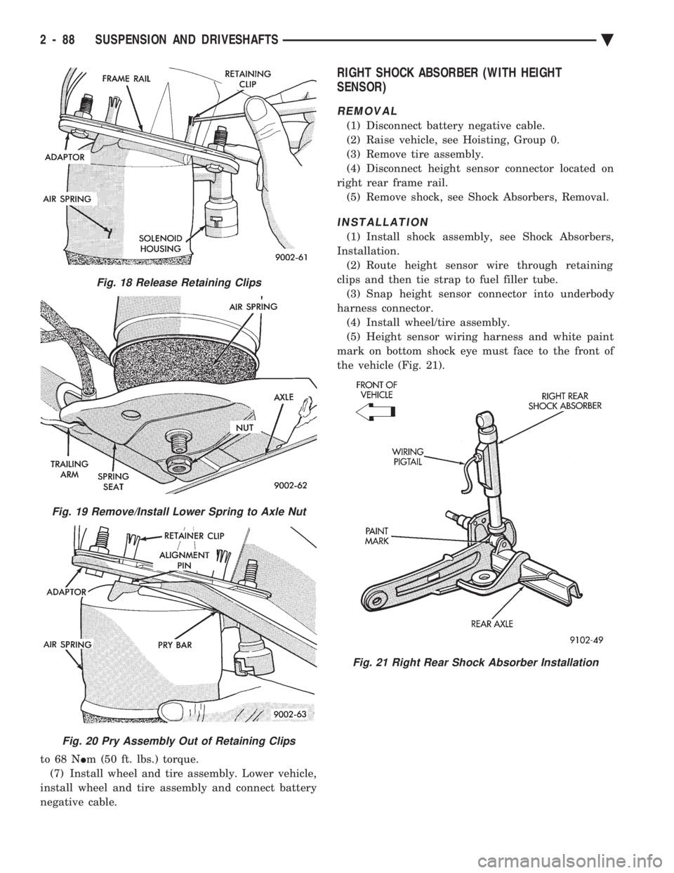
clips. (Fig. 18) (5) Remove lower spring to axle nut (Fig. 19).
(6) Pry assembly down to pull alignment studs
through retaining clips (Fig. 20). Remove assembly.
INSTALLATION
(1) Position assembly lower stud into axle seat and
upper alignment pins through frame rail adaptor. (2) Install upper retaining clips.
(3) Install lower spring to axle nut: LOOSE AS-
SEMBLE. (4) Install solenoid and connect air line and electri-
cal connector. (5) Charge (inflate) air spring. See RECHARGING
AIR SPRING and add air for 60 seconds. (6) AFTER partial air recharge tighten lower nut
Fig. 17 Air Strut Upper Mount Assembly
Ä SUSPENSION AND DRIVESHAFTS 2 - 87
Page 146 of 2438
to 68 N Im (50 ft. lbs.) torque.
(7) Install wheel and tire assembly. Lower vehicle,
install wheel and tire assembly and connect battery
negative cable.
RIGHT SHOCK ABSORBER (WITH HEIGHT
SENSOR)
REMOVAL
(1) Disconnect battery negative cable.
(2) Raise vehicle, see Hoisting, Group 0.
(3) Remove tire assembly.
(4) Disconnect height sensor connector located on
right rear frame rail. (5) Remove shock, see Shock Absorbers, Removal.
INSTALLATION
(1) Install shock assembly, see Shock Absorbers,
Installation. (2) Route height sensor wire through retaining
clips and then tie strap to fuel filler tube. (3) Snap height sensor connector into underbody
harness connector. (4) Install wheel/tire assembly.
(5) Height sensor wiring harness and white paint
mark on bottom shock eye must face to the front of
the vehicle (Fig. 21).
Fig. 18 Release Retaining Clips
Fig. 19 Remove/Install Lower Spring to Axle Nut
Fig. 20 Pry Assembly Out of Retaining Clips
Fig. 21 Right Rear Shock Absorber Installation
2 - 88 SUSPENSION AND DRIVESHAFTS Ä
Page 149 of 2438
SPECIFICATIONS
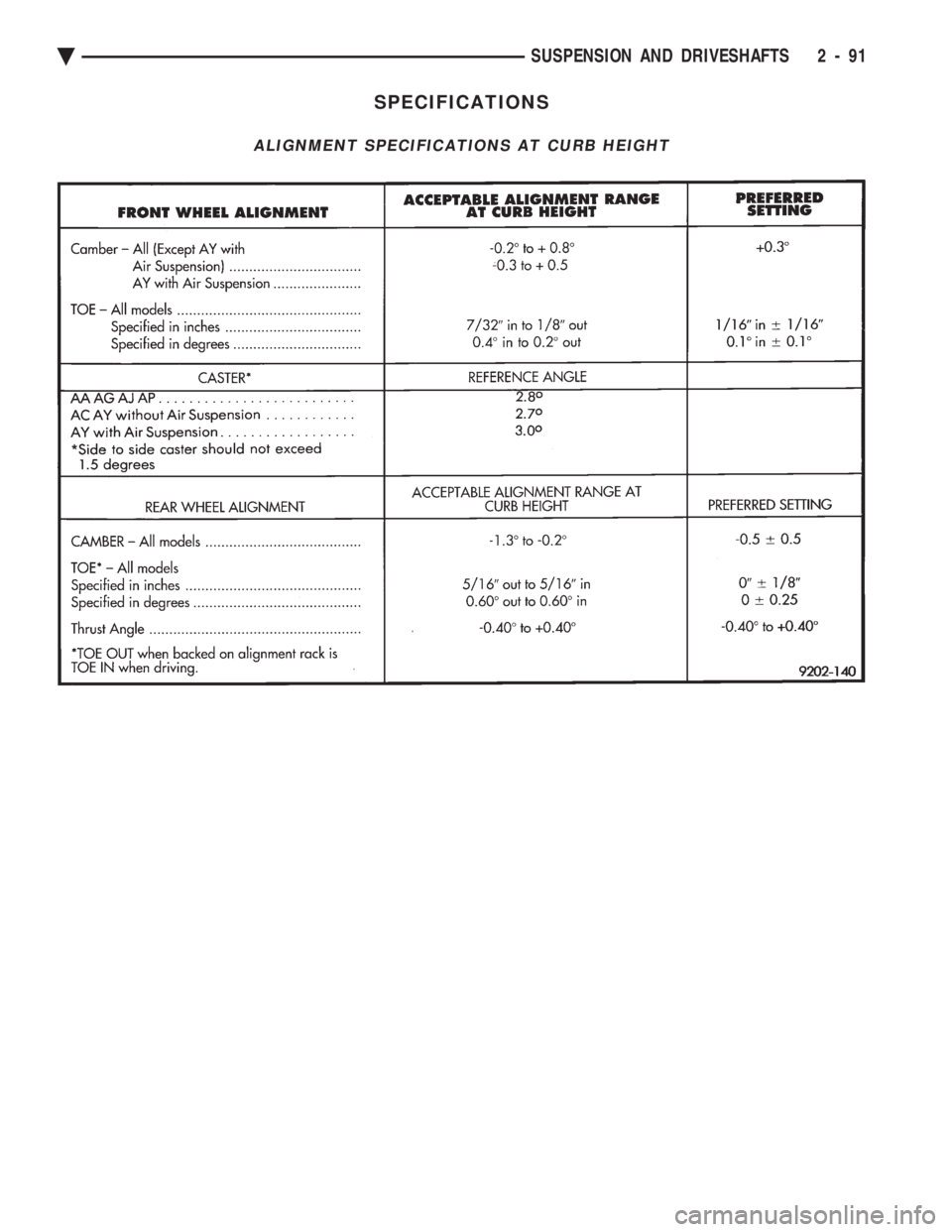
ALIGNMENT SPECIFICATIONS AT CURB HEIGHT
Ä SUSPENSION AND DRIVESHAFTS 2 - 91
Page 228 of 2438

pared by the (CAB) and used to detect brake system
faults that would require Anti -Lock Braking to be
disabled.The Boost Pressure Transducer is mounted on the
bottom of the hydraulic assembly, (Fig. 1) and moni-
tors booster servo pressure. The Primary Pressure
Transducer is mounted on the left side of the hydrau-
lic assembly and monitors primary master cylinder
pressure.
DIFFERENTIAL PRESSURE SWITCH
A non-latching Differential Pressure Switch is used
to detect a pressure difference greater than 2,068
kPa (300 psi.) between the primary and secondary
master cylinder hydraulic circuits. If detected, the
Differential Pressure Switch grounds the output of
the primary pressure transducer (circuit B-218). This
results in a 0.0 volt signal from the Primary Pres-
sure Transducer that is sensed by the (CAB) as a dif-
ferential pressure fault. The (CAB) will then light
the Red Brake Warning Lamp and the Amber Anti-
Lock Warning Lamp and disable the Anti-Lock brak-
ing function. See Fig. 1 for location of the differential
pressure switch.
PROPORTIONING VALVES
The ABS system uses screw-in Proportioning
Valves in place of the conventional Height Sensing Proportioning Valve. Each rear brake circuit has its
own screw-in Proportioning Valve that is attached to
the rear brake outlet ports of the hydraulic assembly
(Fig. 1). These valves limit brake pressure to the
rear brakes after a certain brake pressure is reached.
This improves front to rear wheel brake balance dur-
ing normal braking.
FILTERS-SERVICEABILITY
There is a screen filter in each of the two master
cylinder fill ports. There is also a low pressure filter
for the pump/motor. The filter is integral to the
Pump/Motor low pressure hose.
FLUID LEVEL SWITCH
A Low Fluid Switch is located in the hydraulic as-
sembly fluid reservoir, (Fig. 1). The switch consists of
a float and magnetic reed switch that closes when
low fluid is detected. The Low Fluid Switch is used
as an input, to the Red Brake Warning Lamp, the
(CAB), and the EVIC (if so equipped). When a low
fluid condition exists the switch will close, grounding
the low fluid circuit and illuminating the Red Brake
Warning Lamp. The (CAB) will disable the Anti-
Lock Function and light the Amber Anti-Lock Warn-
ing Lamp if vehicle is in motion above 3 mph. If
vehicle is not in motion, the Amber Anti-Lock Warn-
ing Lamp will NOT be lit.
DUAL FUNCTION PRESSURE SWITCH WIRING DIAGRAM
5 - 78 ANTI-LOCK 10 BRAKE SYSTEM Ä
Page 1063 of 2438
WIRING DIAGRAMS AC-AY BODY INDEX
Wiring Diagram
Name Sheet Number
ABS Data Link Connector ........................49
Airbag System ........................... .57, 58
Clockspring ...............................57
Diagnostic Module ..........................57
Interface Grommet ..........................58
Sensor-Left ...............................58
Sensor-Right ..............................58
Squib (Airbag Igniter) ........................57
Air Conditioning and Heater System (2.5L) .............53
A/C Switch ...............................53
Blower Motor ..............................53
Compressor ...............................53
Defrost Switch .............................53
Diode ...................................53
Illumination Lamps ..........................53
Low Pressure Switch .........................53
Resistor .................................53
Switch-Blower .............................53
Air Conditioning Variable Output Compressor ..........113
Air Exhaust Solenoid-Automatic Air Load Leveling ........40
Air Suspension System .................41, 42, 43, 44
Air Exhaust Solenoid .........................42
Air Suspension Relay .........................42
Air Suspension System Control Module .......41, 43, 176
Compressor Assembly ........................42
Compressor Motor ..........................42
Height Sensors ............................44
Shock Absorber ............................43
Solenoids ............................ .41, 44
Air Suspension System Control Module .........41, 43, 176
Antennas ............................. .118, 126
Anti-Lock Brake System ............45, 46, 47, 48, 49, 50
ABS System Relay ..........................47
Controller .................. .45, 46, 47, 48, 49, 50
Data Link Connector .........................49
Left Front Wheel Sensor .......................50
Left Rear Wheel Sensor .......................50
Modulator ............................ .45, 48
Pump Motor ..............................46
Pump and Motor Relay .......................46
Right Front Wheel Sensor ......................50
Right Rear Wheel Sensor ......................50
Yellow Lamp Relay ..........................49
Anti-Lock Brake System Controller .....45, 46, 47, 48, 49, 50
Anti-Lock Brake System Modulator Connectors .........172
Anti-Lock Brake System Controller Connector ..........175
Anti-Lock Brake System Modulator ...............45, 48
ATC In-line Connector ........................ .117
Automatic Air Load Leveling System ..............39, 40
Air Exhaust Solenoid .........................40
Compressor Assembly ........................40
Compressor Motor ..........................40Wiring Diagram
Name Sheet Number
Load Leveling Relay .........................40
Shock Absorber ............................40
Automatic Day/Night Mirror .................... .124
Automatic Temperature Control .............115, 116, 117
A/C Blower Motor ......................... .115
Ambient Sensor .......................... .117
ATC Control Switch ........................ .116
ATC In Line Connector ...................... .117
ATC Power Module ........................ .115
In Car Senso r............................ .115
In Car Sensor Motor ....................... .115
Sun Sensor ............................. .115
Water Sensor ............................ .117
Automatic Temperature Control (Radiator and
Compressor 3.3L & 3.8L) .................. .113, 114
A/C Ambient Temperature Switch ................114
A/C Compressor Clutch Relay ...................113
A/C Fan Cutout Switch ...................... .114
A/C High Pressure Cutout Switch ................114
A/C Low Pressure Switch .................... .114
A/C Variable Output Compressor .................113
Diode ................................. .113
Radiator Fan Motor ........................ .113
Radiator Fan Relay ........................ .114
Automatic Shutdown Relay .......................29
Automatic Temperature Control In-line Connector ........206
Automatic Temperature Control Module Connector .......200
Back-Up Lamp Relay ..........................33
Battery ...............................2,5,7,9
Body Computer 2 (Electronic Cluster) .........101, 102, 194
25-Pin Connector ...................... .101, 102
Body Computer 1 (Electronic Cluster) .........103, 104, 195
25-Pin Connector ...................... .103, 104
Data Link Connector ....................... .103
Halo Lamp .............................. .104
Relay ................................. .103
Body Computer (Mechanical Cluster w/Visual Message Ctr) ......................... .196, 197
Body Computer (Mechanical Cluster w/o Visual Message Ctr) ......................... .198, 199
Body Computer 1 (Mechanical Cluster w/o Visual Message Ctr) ..................... .108, 109, 110
25-Pin Connector ................... .108, 109, 110
Data Link Connector ....................... .110
Halo Lamp .............................. .108
Key-In Switch ............................ .109
Relay Bank ............................. .108
Body Computer 2 (Mechanical Cluster with Visual Message Ctr) ..................... .105, 106, 107
25-Pin Connector ................... .105, 106, 107
Data Link Connector ....................... .106
Halo Lamp .............................. .106
Key-In Switch ............................ .107
Ä WIRING DIAGRAMS AC-AY BODY 8W - 313
Page 1069 of 2438
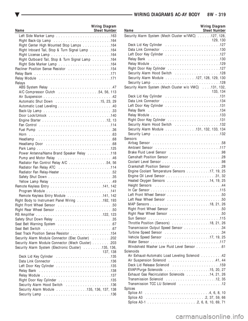
Wiring Diagram
Name Sheet Number
Left Side Marker Lamp ...................... .163
Right Back-Up Lamp ....................... .164
Right Center High Mounted Stop Lamps ............164
Right Inboard Tail, Stop & Turn Signal Lamp .........164
Right License Lamp ........................ .164
Right Outboard Tail, Stop & Turn Signal Lamp ........164
Right Side Marker Lamp ..................... .164
Recliner Position Sense Resistor ..................154
Relay Bank ............................... .171
Relay Module ............................. .171
Relays ABS System Relay ..........................47
A/C Compressor Clutch .................54, 56, 113
Air Suspension .............................42
Automatic Shut Down .................. .15, 23, 29
Automatic Load Leveling .......................40
Back-Up Lamp .............................33
Door Lock/Unlock ......................... .140
Engine Starter .......................... .12, 13
Fan Control ............................. .114
Fuel Pump ...............................36
Horn ...................................63
Headlamp ................................68
Headlamp Door ............................68
Park Lamp .............................. .125
Power Antenna/Name Brand Speaker Relay ..........118
Pump and Motor Relay .......................46
Radiator Fan Control Relay A/C ................54, 56
Radiator Fan Relay ATC ..................... .114
Radiator Fan Relay-Heater ......................52
Safety Shut Down ...........................35
Yellow Lamp Relay ..........................49
Remote Keyless Entry ..................... .141, 142
Program Module .......................... .141
Remote Keyless Entry Module ...............141, 142
Right Body to Instrument Panel Wiring ...........192, 193
Right Front Wheel Sensor .......................50
Right Rear Wheel Sensor ........................50
RS Amplifier ........................... .122, 123
Safety Shut Down Relay ........................35
Seat Belt Warning System .......................67
Seat Belt Switch .............................67
Seat Track Position Sense Resistor .................154
Security Alarm Module Connector (Elec Cluster) ........202
Security Alarm Module Connector (Mech Cluster) ........203
Security Alarm System (Electronic Cluster) ........135, 136,
137, 138
Deck Lid Key Cylinder ...................... .135
Data Link Connector ....................... .136
Left Door Key Cylinder ...................... .135
Relay Bank ............................. .138
Relay Module ............................ .137
Right Door Key Cylinder ..................... .135
Security Alarm Hood Switch ...................136
Security Alarm Module .............135, 136, 137, 138
Security Lamp ........................... .136Wiring Diagram
Name Sheet Number
Security Alarm System (Mech Cluster w/VMC) ......127, 128,
129, 130
Deck Lid Key Cylinder ...................... .127
Data Link Connector ....................... .130
Left Door Key Cylinder ...................... .127
Relay Bank ............................. .130
Relay Module ............................ .129
Right Door Key Cylinder ..................... .127
Security Alarm Hood Switch ...................128
Security Alarm Module .............127, 128, 129, 130
Security Lamp ........................... .128
Security Alarm System (Mech Cluster w/o VMC) . . . .131, 132,
133, 134
Deck Lid Key Cylinder ...................... .131
Data Link Connector ....................... .134
Left Door Key Cylinder ...................... .131
Relay Bank ............................. .134
Relay Module ............................ .133
Right Door Key Cylinder ..................... .131
Security Alarm Hood Switch ...................132
Security Alarm Module .............131, 132, 133, 134
Security Lamp ........................... .132
Sensors Airbag Sensor .............................58
Ambient Sensor .......................... .117
Brake Fluid Level Sensor ......................98
Camshaft Position Sensor ......................28
Coolant Level Sensor .........................98
Crankshaft Position Sensor .....................28
Engine Coolant Temperature Sensors ..........17, 19, 25
Engine Oil Level Sensor .................... .31, 32
Heated Oxygen Sensors ................. .14, 19, 25
Height Sensors ............................44
In Car Senso r............................ .115
Left Front Wheel Sensor .......................50
Left Rear Wheel Sensor .......................50
MAP Sensors ........................ .18, 21, 26
Right Front Wheel Sensor ......................50
Right Rear Wheel Sensor ......................50
Sun Sensor ............................. .115
Throttle Position (Sensors) ................18, 21, 26
Transmission Output Speed Sensor ................34
Turbine Speed Sensor ........................34
Vehicle Speed Sensor .................. .17, 19, 25
Water Sensor ............................ .117
Windshield Washer Low Fluid Level Sensor ...........61
Solenoids Air Exhaust-Automatic Load Leveling Solenoid .........42
Air Suspension Solenoid ................... .41, 44
Deck Lid Release Solenoid ................... .159
EVAP/Purge Solenoids .................. .15, 20, 27
Exhaust Gas Recirculation Solenoids ..........14, 21, 26
Transmission Solenoid .................... .12, 35
Transmission TCC LU Solenoid ..................12
Splices Splice A1 ...........................4,6,8,10
Splice A3 .........................2,37,59,66
Splice A3-1 .....................2,6,8,10,69,71
Ä WIRING DIAGRAMS AC-AY BODY 8W - 319