1993 CHEVROLET PLYMOUTH ACCLAIM height
[x] Cancel search: heightPage 1594 of 2438
springs using Tool C-3422-B. (2) Remove valve retaining locks, valve spring re-
tainers, valve stem seals and valve springs. (3) Before removing valves, remove any burrs
from valve stem lock grooves to prevent damage
to the valve guides. Identify valves to insure instal-
lation in original location.
VALVE INSPECTION (1) Clean valves thoroughly and discard burned,
warped and cracked valves. (2) Measure valve stems for wear.
(3) If valve stems are worn more than 0.05 mm (.002
inch.) replace valve.
VALVE GUIDES
(1) Remove carbon and varnish deposits from inside
of valve guides with a reliable guide cleaner. (2) Checking Valve Guide Wear:
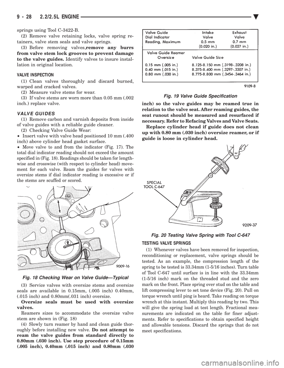
² Insert valve with valve head positioned 10 mm (.400
inch) above cylinder head gasket surface.
²
Move valve to and from the indicator (Fig. 17). The
total dial indicator reading should not exceed the amount
specified in (Fig. 18). Readings should be taken for length-
wise and crosswise (with respect to cylinder head) move-
ment for each valve. Ream the guides for valves with
oversize stems if dial indicator reading is excessive or if
the stems are scuffed or scored.
(3) Service valves with oversize stems and oversize
seals are available in 0.15mm, (.005 inch) 0.40mm,
(.015 inch) and 0.80mm(.031 inch) oversize. Oversize seals must be used with oversize
valves. Reamers sizes to accommodate the oversize valve
stem are shown in (Fig. 18)
(4) Slowly turn reamer by hand and clean guide thor-
oughly before installing new valve. Do not attempt to
ream the valve guides from standard directly to
0.80mm (.030 inch). Use step procedure of 0.15mm
(.005 inch), 0.40mm (.015 inch) and 0.80mm (.030 inch) so the valve guides may be reamed true in
relation to the valve seat. After reaming guides, the
seat runout should be measured and resurfaced if
necessary. Refer to Refacing Valves and Valve Seats.
Replace cylinder head if guide does not clean
up with 0.80 mm (.030 inch) oversize reamer, or if
guide is loose in cylinder head.
TESTING VALVE SPRINGS
(1) Whenever valves have been removed for inspection,
reconditioning or replacement, valve springs should be
tested. As an example, the compression length of the
spring to be tested is 33.34mm (1-5/16 inches). Turn table
of Tool C-647 until surface is in line with the 33.34mm
(1-5/16 inch) mark on the threaded stud and the zero
mark on the front. Place spring over stud on the table and
lift compressing lever to set tone device (Fig. 20). Pull on
torque wrench until ping is heard. Take reading on torque
wrench at this instant. Multiply this reading by two. This
will give the spring load at test length. Fractional mea-
surements are indicated on the table for finer adjust-
ments. Refer to specifications to obtain specified height
and allowable tensions. Discard the springs that do not
meet specifications.
Fig. 18 Checking Wear on Valve GuideÐTypical
Fig. 19 Valve Guide Specification
Fig. 20 Testing Valve Spring with Tool C-647
9 - 28 2.2/2.5L ENGINE Ä
Page 1596 of 2438
(8) Check the valve spring installed height after
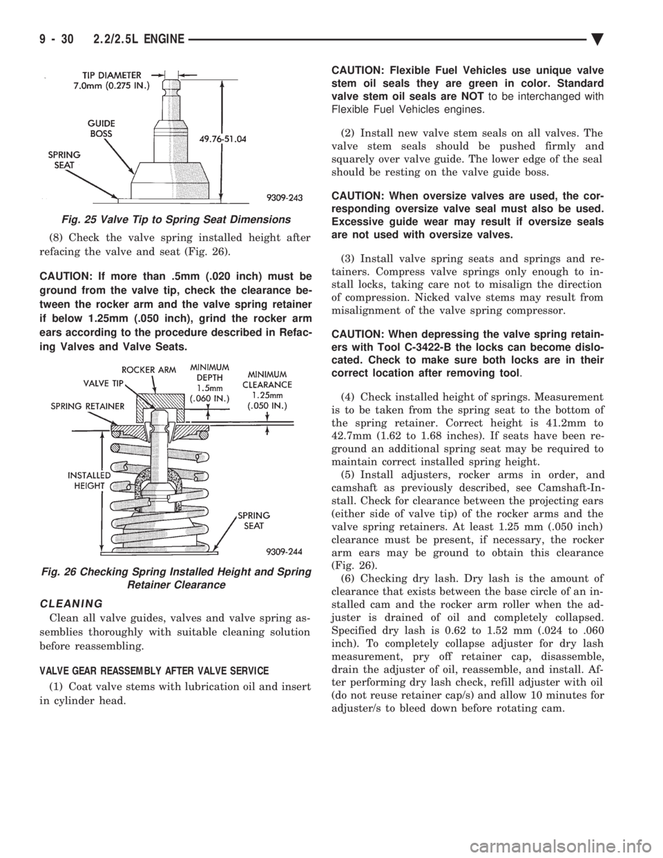
refacing the valve and seat (Fig. 26).
CAUTION: If more than .5mm (.020 inch) must be
ground from the valve tip, check the clearance be-
tween the rocker arm and the valve spring retainer
if below 1.25mm (.050 inch), grind the rocker arm
ears according to the procedure described in Refac-
ing Valves and Valve Seats.
CLEANING
Clean all valve guides, valves and valve spring as-
semblies thoroughly with suitable cleaning solution
before reassembling.
VALVE GEAR REASSEMBLY AFTER VALVE SERVICE (1) Coat valve stems with lubrication oil and insert
in cylinder head. CAUTION: Flexible Fuel Vehicles use unique valve
stem oil seals they are green in color. Standard
valve stem oil seals are NOT to be interchanged with
Flexible Fuel Vehicles engines.
(2) Install new valve stem seals on all valves. The
valve stem seals should be pushed firmly and
squarely over valve guide. The lower edge of the seal
should be resting on the valve guide boss.
CAUTION: When oversize valves are used, the cor-
responding oversize valve seal must also be used.
Excessive guide wear may result if oversize seals
are not used with oversize valves.
(3) Install valve spring seats and springs and re-
tainers. Compress valve springs only enough to in-
stall locks, taking care not to misalign the direction
of compression. Nicked valve stems may result from
misalignment of the valve spring compressor.
CAUTION: When depressing the valve spring retain-
ers with Tool C-3422-B the locks can become dislo-
cated. Check to make sure both locks are in their
correct location after removing tool .
(4) Check installed height of springs. Measurement
is to be taken from the spring seat to the bottom of
the spring retainer. Correct height is 41.2mm to
42.7mm (1.62 to 1.68 inches). If seats have been re-
ground an additional spring seat may be required to
maintain correct installed spring height. (5) Install adjusters, rocker arms in order, and
camshaft as previously described, see Camshaft-In-
stall. Check for clearance between the projecting ears
(either side of valve tip) of the rocker arms and the
valve spring retainers. At least 1.25 mm (.050 inch)
clearance must be present, if necessary, the rocker
arm ears may be ground to obtain this clearance
(Fig. 26). (6) Checking dry lash. Dry lash is the amount of
clearance that exists between the base circle of an in-
stalled cam and the rocker arm roller when the ad-
juster is drained of oil and completely collapsed.
Specified dry lash is 0.62 to 1.52 mm (.024 to .060
inch). To completely collapse adjuster for dry lash
measurement, pry off retainer cap, disassemble,
drain the adjuster of oil, reassemble, and install. Af-
ter performing dry lash check, refill adjuster with oil
(do not reuse retainer cap/s) and allow 10 minutes for
adjuster/s to bleed down before rotating cam.
Fig. 25 Valve Tip to Spring Seat Dimensions
Fig. 26 Checking Spring Installed Height and Spring Retainer Clearance
9 - 30 2.2/2.5L ENGINE Ä
Page 1605 of 2438
REFACING VALVES AND VALVE SEATS
(1) The intake and exhaust valve seats and valve
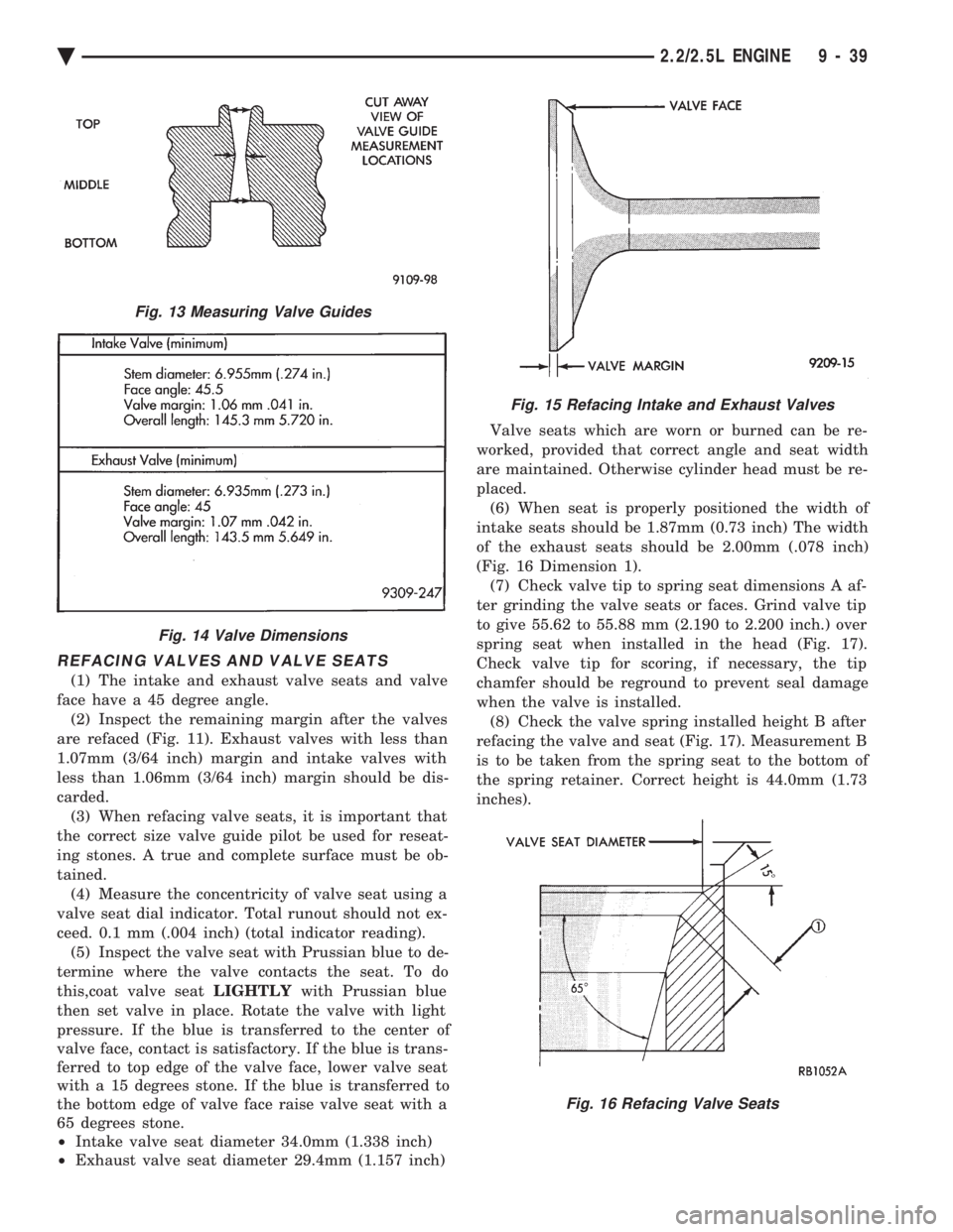
face have a 45 degree angle. (2) Inspect the remaining margin after the valves
are refaced (Fig. 11). Exhaust valves with less than
1.07mm (3/64 inch) margin and intake valves with
less than 1.06mm (3/64 inch) margin should be dis-
carded. (3) When refacing valve seats, it is important that
the correct size valve guide pilot be used for reseat-
ing stones. A true and complete surface must be ob-
tained. (4) Measure the concentricity of valve seat using a
valve seat dial indicator. Total runout should not ex-
ceed. 0.1 mm (.004 inch) (total indicator reading). (5) Inspect the valve seat with Prussian blue to de-
termine where the valve contacts the seat. To do
this,coat valve seat LIGHTLYwith Prussian blue
then set valve in place. Rotate the valve with light
pressure. If the blue is transferred to the center of
valve face, contact is satisfactory. If the blue is trans-
ferred to top edge of the valve face, lower valve seat
with a 15 degrees stone. If the blue is transferred to
the bottom edge of valve face raise valve seat with a
65 degrees stone.
² Intake valve seat diameter 34.0mm (1.338 inch)
² Exhaust valve seat diameter 29.4mm (1.157 inch) Valve seats which are worn or burned can be re-
worked, provided that correct angle and seat width
are maintained. Otherwise cylinder head must be re-
placed. (6) When seat is properly positioned the width of
intake seats should be 1.87mm (0.73 inch) The width
of the exhaust seats should be 2.00mm (.078 inch)
(Fig. 16 Dimension 1). (7) Check valve tip to spring seat dimensions A af-
ter grinding the valve seats or faces. Grind valve tip
to give 55.62 to 55.88 mm (2.190 to 2.200 inch.) over
spring seat when installed in the head (Fig. 17).
Check valve tip for scoring, if necessary, the tip
chamfer should be reground to prevent seal damage
when the valve is installed. (8) Check the valve spring installed height B after
refacing the valve and seat (Fig. 17). Measurement B
is to be taken from the spring seat to the bottom of
the spring retainer. Correct height is 44.0mm (1.73
inches).
Fig. 13 Measuring Valve Guides
Fig. 14 Valve Dimensions
Fig. 15 Refacing Intake and Exhaust Valves
Fig. 16 Refacing Valve Seats
Ä 2.2/2.5L ENGINE 9 - 39
Page 1606 of 2438
VALVE GEAR REASSEMBLY AFTER VALVE SERVICE
(1) Coat valve stems with lubrication oil and insert
in cylinder head. (2) Install new valve stem seals on all valves. The
valve stem seals should be pushed firmly and
squarely over valve guide. The lower edge of the seal
should be resting on the valve guide boss. (3) Install valve spring seats and springs and re-
tainers. Compress valve springs only enough to in-
stall locks, taking care not to misalign the direction
of compression. Nicked valve stems may result from
misalignment of the valve spring compressor.
CAUTION: When depressing the valve spring retain-
ers with Valve Spring Compressor Tool C-3422-B
with adopters 6537 and 6526 (Fig. 11) the locks can
become dislocated. Check to make sure both locks
are in their correct location after removing tool.
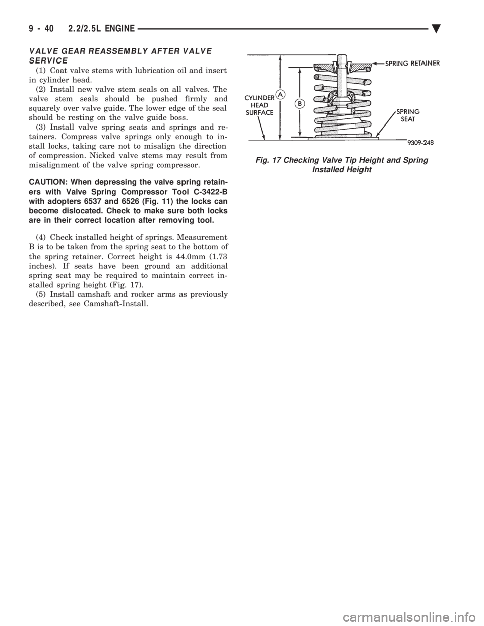
(4) Check installed height of springs. Measurement
B is to be taken from the spring seat to the bottom of
the spring retainer. Correct height is 44.0mm (1.73
inches). If seats have been ground an additional
spring seat may be required to maintain correct in-
stalled spring height (Fig. 17). (5) Install camshaft and rocker arms as previously
described, see Camshaft-Install.
Fig. 17 Checking Valve Tip Height and Spring Installed Height
9 - 40 2.2/2.5L ENGINE Ä
Page 1633 of 2438
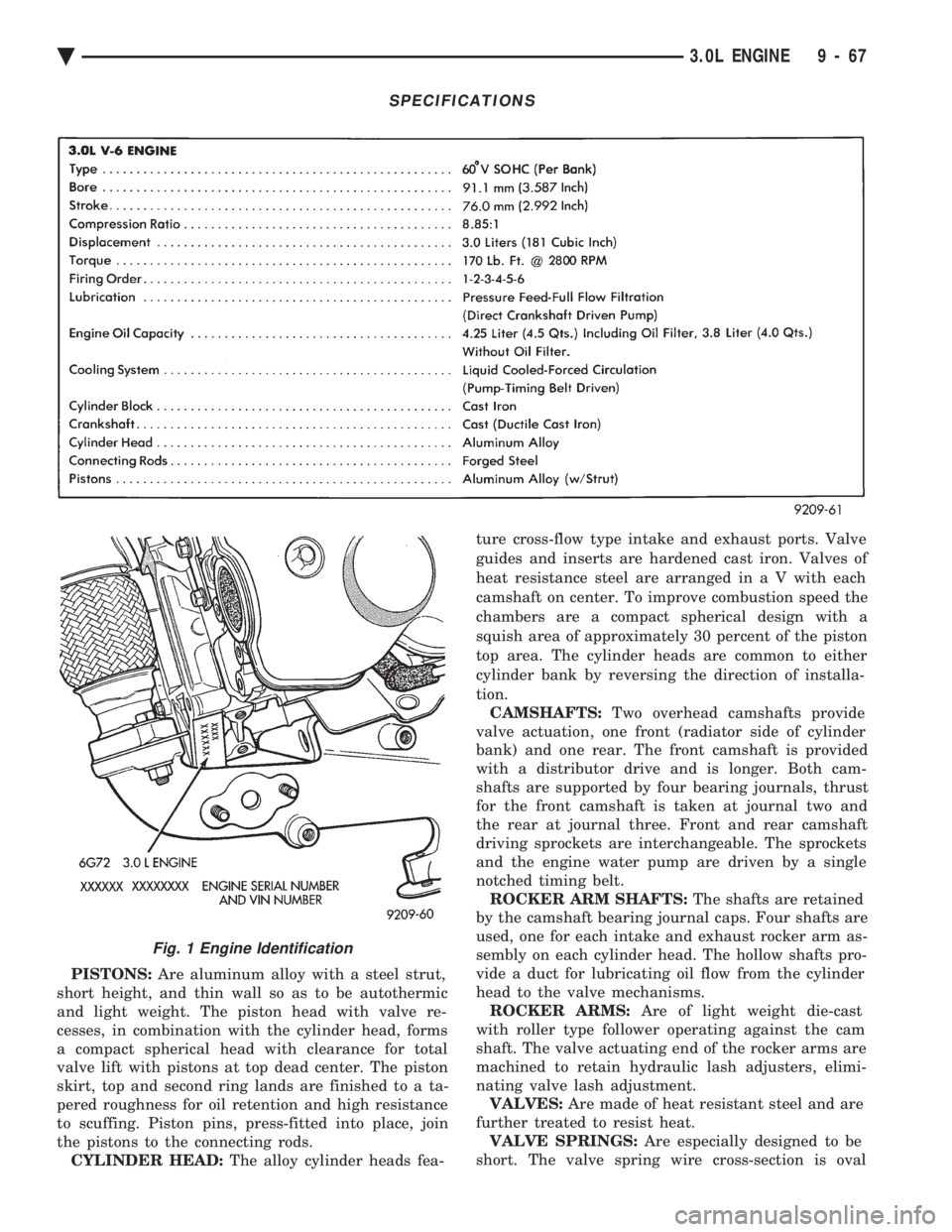
PISTONS: Are aluminum alloy with a steel strut,
short height, and thin wall so as to be autothermic
and light weight. The piston head with valve re-
cesses, in combination with the cylinder head, forms
a compact spherical head with clearance for total
valve lift with pistons at top dead center. The piston
skirt, top and second ring lands are finished to a ta-
pered roughness for oil retention and high resistance
to scuffing. Piston pins, press-fitted into place, join
the pistons to the connecting rods. CYLINDER HEAD: The alloy cylinder heads fea- ture cross-flow type intake and exhaust ports. Valve
guides and inserts are hardened cast iron. Valves of
heat resistance steel are arranged i
n a V with each
camshaft on center. To improve combustion speed the
chambers are a compact spherical design with a
squish area of approximately 30 percent of the piston
top area. The cylinder heads are common to either
cylinder bank by reversing the direction of installa-
tion. CAMSHAFTS: Two overhead camshafts provide
valve actuation, one front (radiator side of cylinder
bank) and one rear. The front camshaft is provided
with a distributor drive and is longer. Both cam-
shafts are supported by four bearing journals, thrust
for the front camshaft is taken at journal two and
the rear at journal three. Front and rear camshaft
driving sprockets are interchangeable. The sprockets
and the engine water pump are driven by a single
notched timing belt. ROCKER ARM SHAFTS: The shafts are retained
by the camshaft bearing journal caps. Four shafts are
used, one for each intake and exhaust rocker arm as-
sembly on each cylinder head. The hollow shafts pro-
vide a duct for lubricating oil flow from the cylinder
head to the valve mechanisms. ROCKER ARMS: Are of light weight die-cast
with roller type follower operating against the cam
shaft. The valve actuating end of the rocker arms are
machined to retain hydraulic lash adjusters, elimi-
nating valve lash adjustment. VALVES: Are made of heat resistant steel and are
further treated to resist heat. VALVE SPRINGS: Are especially designed to be
short. The valve spring wire cross-section is oval
SPECIFICATIONS
Fig. 1 Engine Identification
Ä 3.0L ENGINE 9 - 67
Page 1642 of 2438
CAMSHAFT SERVICE
SEE AUTO LASH ADJUSTER FUNCTION CHECK BEFORE DISASSEMBLY
REMOVAL
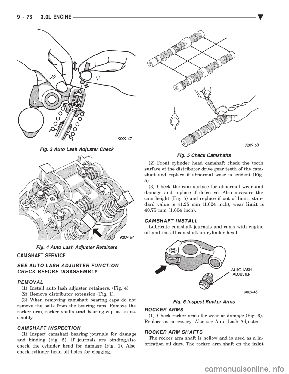
(1) Install auto lash adjuster retainers. (Fig. 4).
(2) Remove distributor extension (Fig. 1).
(3) When removing camshaft bearing caps do not
remove the bolts from the bearing caps. Remove the
rocker arm, rocker shafts andbearing cap as an as-
sembly.
CAMSHAFT INSPECTION
(1) Inspect camshaft bearing journals for damage
and binding (Fig. 5). If journals are binding,also
check the cylinder head for damage (Fig. 1). Also
check cylinder head oil holes for clogging. (2) Front cylinder head camshaft check the tooth
surface of the distributor drive gear teeth of the cam-
shaft and replace if abnormal wear is evident (Fig.
5). (3) Check the cam surface for abnormal wear and
damage and replace if defective. Also measure the
cam height (Fig. 5) and replace if out of limit, stan-
dard value is 41.25 mm (1.624 inch), wear limitis
40.75 mm (1.604 inch).
CAMSHAFT INSTALL
Lubricate camshaft journals and cams with engine
oil and install camshaft on cylinder head.
ROCKER ARMS
(1) Check rocker arms for wear or damage (Fig. 6).
Replace as necessary. Also see Auto Lash Adjuster.
ROCKER ARM SHAFTS
The rocker arm shaft is hollow and is used as a lu-
brication oil duct. The rocker arm shaft on the inlet
Fig. 3 Auto Lash Adjuster Check
Fig. 4 Auto Lash Adjuster Retainers
Fig. 5 Check Camshafts
Fig. 6 Inspect Rocker Arms
9 - 76 3.0L ENGINE Ä
Page 1646 of 2438
INSTALLATION
(1) Clean surfaces of head and block, install head
gasket over locating dowels. (2) Install head on locating dowels.
(3) Install 10mm allen hex head bolts with wash-
ers. (4) Tighten bolts in the order shown in (Fig. 16).
When tightening the cylinder head bolts, tighten
gradually, working in two or three steps and finally
tighten to specified torque of 108 N Im (80 ft. lbs.).
VALVE SERVICE
VALVE AND VALVE SPRINGS
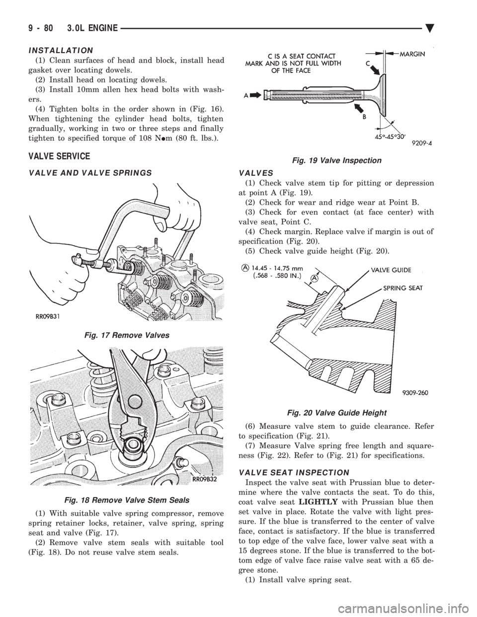
(1) With suitable valve spring compressor, remove
spring retainer locks, retainer, valve spring, spring
seat and valve (Fig. 17). (2) Remove valve stem seals with suitable tool
(Fig. 18). Do not reuse valve stem seals.
VALVES
(1) Check valve stem tip for pitting or depression
at point A (Fig. 19). (2) Check for wear and ridge wear at Point B.
(3) Check for even contact (at face center) with
valve seat, Point C. (4) Check margin. Replace valve if margin is out of
specification (Fig. 20). (5) Check valve guide height (Fig. 20).
(6) Measure valve stem to guide clearance. Refer
to specification (Fig. 21). (7) Measure Valve spring free length and square-
ness (Fig. 22). Refer to (Fig. 21) for specifications.
VALVE SEAT INSPECTION
Inspect the valve seat with Prussian blue to deter-
mine where the valve contacts the seat. To do this,
coat valve seat LIGHTLYwith Prussian blue then
set valve in place. Rotate the valve with light pres-
sure. If the blue is transferred to the center of valve
face, contact is satisfactory. If the blue is transferred
to top edge of the valve face, lower valve seat with a
15 degrees stone. If the blue is transferred to the bot-
tom edge of valve face raise valve seat with a 65 de-
gree stone. (1) Install valve spring seat.
Fig. 17 Remove Valves
Fig. 18 Remove Valve Stem Seals
Fig. 19 Valve Inspection
Fig. 20 Valve Guide Height
9 - 80 3.0L ENGINE Ä
Page 1672 of 2438
REFACING VALVES AND VALVE SEATS
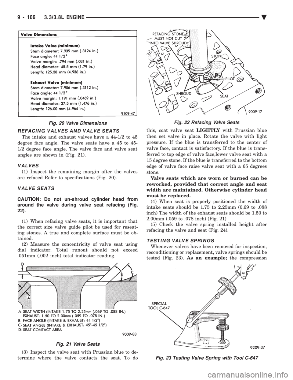
The intake and exhaust valves have a 44-1/2 to 45
degree face angle. The valve seats have a 45 to 45-
1/2 degree face angle. The valve face and valve seat
angles are shown in (Fig. 21).
VALVES
(1) Inspect the remaining margin after the valves
are refaced Refer to specifications (Fig. 20).
VALVE SEATS
CAUTION: Do not un-shroud cylinder head from
around the valve during valve seat refacing (Fig.
22).
(1) When refacing valve seats, it is important that
the correct size valve guide pilot be used for reseat-
ing stones. A true and complete surface must be ob-
tained. (2) Measure the concentricity of valve seat using
dial indicator. Total runout should not exceed
.051mm (.002 inch) total indicator reading.
(3) Inspect the valve seat with Prussian blue to de-
termine where the valve contacts the seat. To do this, coat valve seat
LIGHTLYwith Prussian blue
then set valve in place. Rotate the valve with light
pressure. If the blue is transferred to the center of
valve face, contact is satisfactory. If the blue is trans-
ferred to top edge of valve face,lower valve seat with a
15 degree stone. If the blue is transferred to the bottom
edge of valve face raise valve seat with a 65 degrees
stone. Valve seats which are worn or burned can be
reworked, provided that correct angle and seat
width are maintained. Otherwise cylinder head
must be replaced. (4) When seat is properly positioned the width of
intake seats should be 1.75 to 2.25mm (0.69 to .088
inch) The width of the exhaust seats should be 1.50 to
2.00mm (.059 to .078 inch) (Fig. 21) (5) Check the valve spring installed height after
refacing the valve and seat (Fig. 24).
TESTING VALVE SPRINGS
Whenever valves have been removed for inspection,
reconditioning or replacement, valve springs should be
tested (Fig. 23). As an example; the compression
Fig. 23 Testing Valve Spring with Tool C-647
Fig. 20 Valve Dimensions
Fig. 21 Valve Seats
Fig. 22 Refacing Valve Seats
9 - 106 3.3/3.8L ENGINE Ä