1993 CHEVROLET PLYMOUTH ACCLAIM height
[x] Cancel search: heightPage 1673 of 2438
length of the spring to be tested is 33.34mm (1-5/16
inches). Turn table of Tool C-647 until surface is in line
with the 33.34mm (1-5/16 inch) mark on the threaded
stud and the zero mark on the front. Place spring over
stud on the table and lift compressing lever to set tone
device. Pull on torque wrench until ping is heard. Take
reading on torque wrench at this instant. Multiply this
reading by two. This will give the spring load at test
length. Fractional measurements are indicated on the
table for finer adjustments. Refer to specifications to
obtain specified height and allowable tensions. Discard
the springs that do not meet specifications.
VALVE INSTALLATION
(1) Coat valve stems with clean engine oil and insert
them in cylinder head. (2) Check valve tip to spring seat dimension A after
grinding the valve seats or faces. Grind valve tip to give
49.541 to 51.271 mm (1.950 to 2.018 inch.) over spring
seat when installed in the head (Fig. 17). Check valve
tip for scoring, if necessary, the tip chamfer should be
reground to prevent seal damage when the valve is
installed. (3) Install new cup seals on all valve stems and over
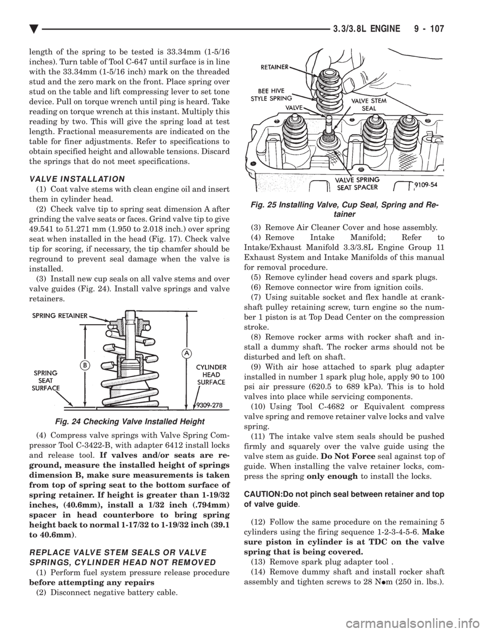
valve guides (Fig. 24). Install valve springs and valve
retainers.
(4) Compress valve springs with Valve Spring Com-
pressor Tool C-3422-B, with adapter 6412 install locks
and release tool. If valves and/or seats are re-
ground, measure the installed height of springs
dimension B, make sure measurements is taken
from top of spring seat to the bottom surface of
spring retainer. If height is greater than 1-19/32
inches, (40.6mm), install a 1/32 inch (.794mm)
spacer in head counterbore to bring spring
height back to normal 1-17/32 to 1-19/32 inch (39.1
to 40.6mm) .
REPLACE VALVE STEM SEALS OR VALVE
SPRINGS, CYLINDER HEAD NOT REMOVED
(1) Perform fuel system pressure release procedure
before attempting any repairs (2) Disconnect negative battery cable. (3) Remove Air Cleaner Cover and hose assembly.
(4) Remove Intake Manifold; Refer to
Intake/Exhaust Manifold 3.3/3.8L Engine Group 11
Exhaust System and Intake Manifolds of this manual
for removal procedure. (5) Remove cylinder head covers and spark plugs.
(6) Remove connector wire from ignition coils.
(7) Using suitable socket and flex handle at crank-
shaft pulley retaining screw, turn engine so the num-
ber 1 piston is at Top Dead Center on the compression
stroke. (8) Remove rocker arms with rocker shaft and in-
stall a dummy shaft. The rocker arms should not be
disturbed and left on shaft. (9) With air hose attached to spark plug adapter
installed in number 1 spark plug hole, apply 90 to 100
psi air pressure (620.5 to 689 kPa). This is to hold
valves into place while servicing components. (10) Using Tool C-4682 or Equivalent compress
valve spring and remove retainer valve locks and valve
spring. (11) The intake valve stem seals should be pushed
firmly and squarely over the valve guide using the
valve stem as guide. Do Not Forceseal against top of
guide. When installing the valve retainer locks, com-
press the spring only enoughto install the locks.
CAUTION:Do not pinch seal between retainer and top
of valve guide .
(12) Follow the same procedure on the remaining 5
cylinders using the firing sequence 1-2-3-4-5-6. Make
sure piston in cylinder is at TDC on the valve
spring that is being covered. (13) Remove spark plug adapter tool .
(14) Remove dummy shaft and install rocker shaft
assembly and tighten screws to 28 N Im (250 in. lbs.).
Fig. 24 Checking Valve Installed Height
Fig. 25 Installing Valve, Cup Seal, Spring and Re-
tainer
Ä 3.3/3.8L ENGINE 9 - 107
Page 1723 of 2438
FRAME AND BUMPERS
CONTENTS
page page
BUMPER AND FASCIA .................... 1 FRAME................................ 9
BUMPER AND FASCIA INDEX
page page
AA-Vehicle Front Bumper ................... 1
AA-Vehicle Rear Bumper ................... 5
AC-Vehicle Front Bumper ................... 2
AC-Vehicle Rear Bumper ................... 6
AG-Vehicle Front Bumper ................... 3
AG-Vehicle Rear Bumper ................... 7
AJ-Vehicle Front Bumper and Fascia .......... 4 AJ-Vehicle Rear Bumper
.................... 7
AP-Vehicle Front Bumper ................... 4
AP-Vehicle Rear Bumper ................... 7
AY-Vehicle Front Bumper ................... 5
AY-Vehicle Rear Bumper ................... 8
Safety Precautions and Warnings ............. 1
SAFETY PRECAUTIONS AND WARNINGS
WARNING: BUMPER ENERGY ABSORBER UNITS
CONTAIN PRESSURIZE GAS. DO NOT PUNCTURE
OR HEAT ABSORBER UNIT FOR ANY REASON.
PERSONAL INJURY CAN RESULT.
DO NOT VENTURE UNDER A HOISTED VEHICLE
THAT IS NOT SUPPORTED ON SAFETY STANDS.
PERSONAL INJURY CAN RESULT.
CAUTION: To avoid damaging a bright metal or
painted finish bumper or fascia, use a padded work
surface.
AA-VEHICLE FRONT BUMPER
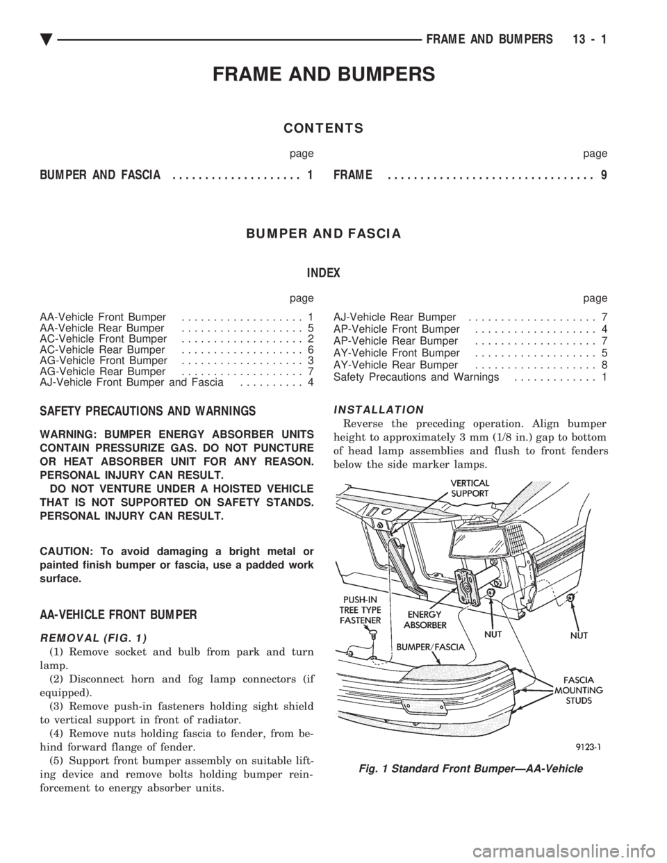
REMOVAL (FIG. 1)
(1) Remove socket and bulb from park and turn
lamp. (2) Disconnect horn and fog lamp connectors (if
equipped). (3) Remove push-in fasteners holding sight shield
to vertical support in front of radiator. (4) Remove nuts holding fascia to fender, from be-
hind forward flange of fender. (5) Support front bumper assembly on suitable lift-
ing device and remove bolts holding bumper rein-
forcement to energy absorber units.
INSTALLATION
Reverse the preceding operation. Align bumper
height to approximately 3 mm (1/8 in.) gap to bottom
of head lamp assemblies and flush to front fenders
below the side marker lamps.
Fig. 1 Standard Front BumperÐAA-Vehicle
Ä FRAME AND BUMPERS 13 - 1
Page 1724 of 2438
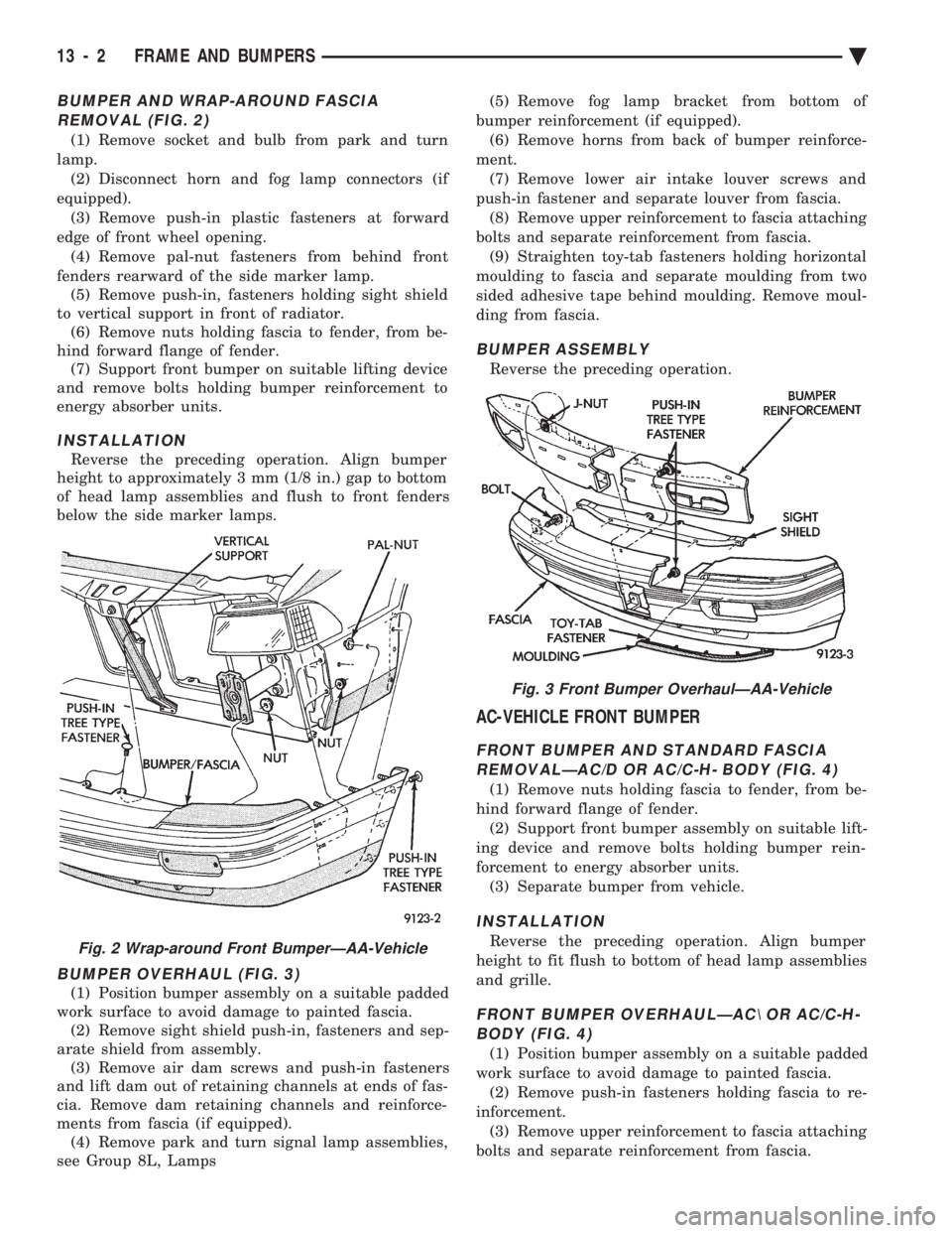
BUMPER AND WRAP-AROUND FASCIA REMOVAL (FIG. 2)
(1) Remove socket and bulb from park and turn
lamp. (2) Disconnect horn and fog lamp connectors (if
equipped). (3) Remove push-in plastic fasteners at forward
edge of front wheel opening. (4) Remove pal-nut fasteners from behind front
fenders rearward of the side marker lamp. (5) Remove push-in, fasteners holding sight shield
to vertical support in front of radiator. (6) Remove nuts holding fascia to fender, from be-
hind forward flange of fender. (7) Support front bumper on suitable lifting device
and remove bolts holding bumper reinforcement to
energy absorber units.
INSTALLATION
Reverse the preceding operation. Align bumper
height to approximately 3 mm (1/8 in.) gap to bottom
of head lamp assemblies and flush to front fenders
below the side marker lamps.
BUMPER OVERHAUL (FIG. 3)
(1) Position bumper assembly on a suitable padded
work surface to avoid damage to painted fascia. (2) Remove sight shield push-in, fasteners and sep-
arate shield from assembly. (3) Remove air dam screws and push-in fasteners
and lift dam out of retaining channels at ends of fas-
cia. Remove dam retaining channels and reinforce-
ments from fascia (if equipped). (4) Remove park and turn signal lamp assemblies,
see Group 8L, Lamps (5) Remove fog lamp bracket from bottom of
bumper reinforcement (if equipped). (6) Remove horns from back of bumper reinforce-
ment. (7) Remove lower air intake louver screws and
push-in fastener and separate louver from fascia. (8) Remove upper reinforcement to fascia attaching
bolts and separate reinforcement from fascia. (9) Straighten toy-tab fasteners holding horizontal
moulding to fascia and separate moulding from two
sided adhesive tape behind moulding. Remove moul-
ding from fascia.
BUMPER ASSEMBLY
Reverse the preceding operation.
AC-VEHICLE FRONT BUMPER
FRONT BUMPER AND STANDARD FASCIA REMOVALÐAC/D OR AC/C-H- BODY (FIG. 4)
(1) Remove nuts holding fascia to fender, from be-
hind forward flange of fender. (2) Support front bumper assembly on suitable lift-
ing device and remove bolts holding bumper rein-
forcement to energy absorber units. (3) Separate bumper from vehicle.
INSTALLATION
Reverse the preceding operation. Align bumper
height to fit flush to bottom of head lamp assemblies
and grille.
FRONT BUMPER OVERHAULÐAC\ OR AC/C-H- BODY (FIG. 4)
(1) Position bumper assembly on a suitable padded
work surface to avoid damage to painted fascia. (2) Remove push-in fasteners holding fascia to re-
inforcement. (3) Remove upper reinforcement to fascia attaching
bolts and separate reinforcement from fascia.
Fig. 2 Wrap-around Front BumperÐAA-Vehicle
Fig. 3 Front Bumper OverhaulÐAA-Vehicle
13 - 2 FRAME AND BUMPERS Ä
Page 1726 of 2438
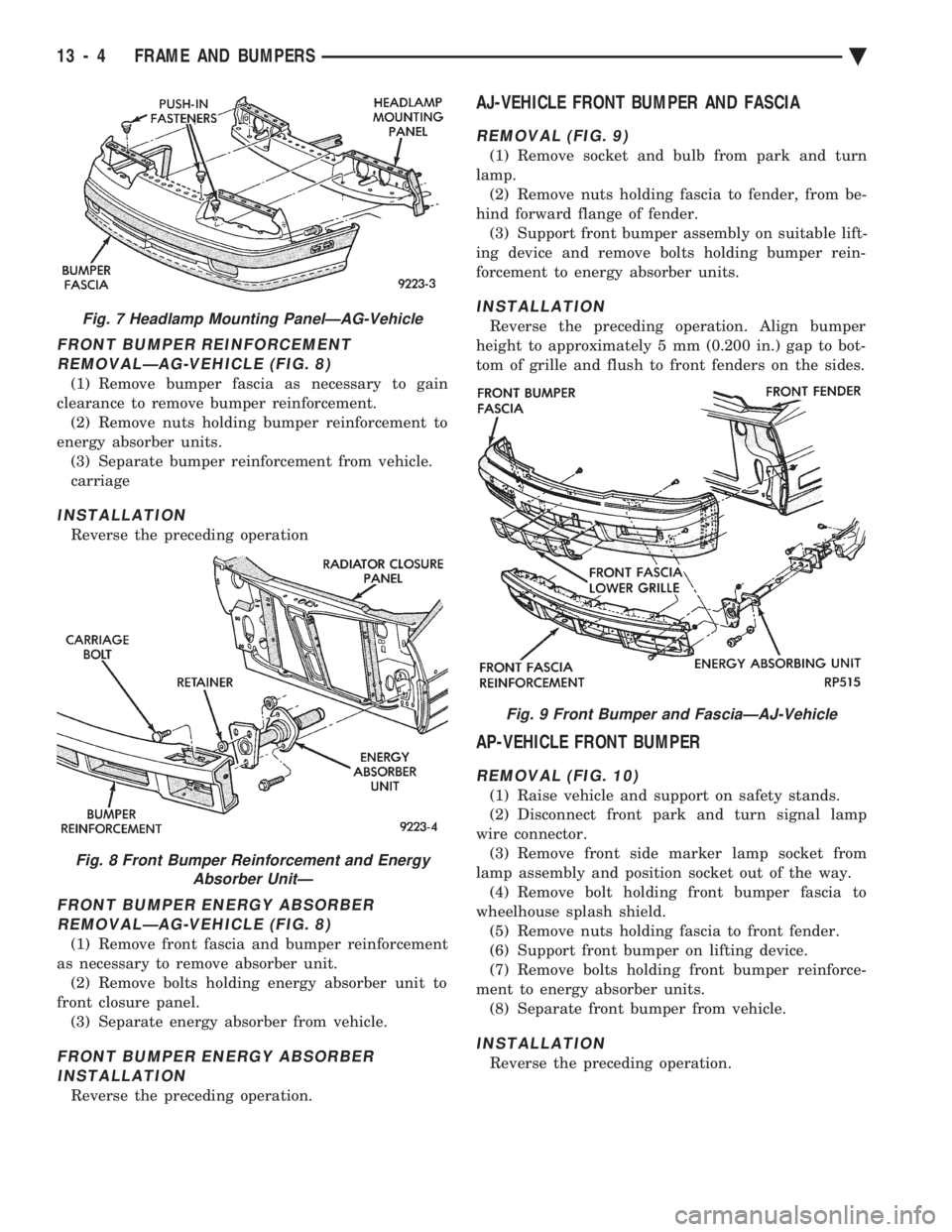
FRONT BUMPER REINFORCEMENT REMOVALÐAG-VEHICLE (FIG. 8)
(1) Remove bumper fascia as necessary to gain
clearance to remove bumper reinforcement. (2) Remove nuts holding bumper reinforcement to
energy absorber units. (3) Separate bumper reinforcement from vehicle.
carriage
INSTALLATION
Reverse the preceding operation
FRONT BUMPER ENERGY ABSORBERREMOVALÐAG-VEHICLE (FIG. 8)
(1) Remove front fascia and bumper reinforcement
as necessary to remove absorber unit. (2) Remove bolts holding energy absorber unit to
front closure panel. (3) Separate energy absorber from vehicle.
FRONT BUMPER ENERGY ABSORBERINSTALLATION
Reverse the preceding operation.
AJ-VEHICLE FRONT BUMPER AND FASCIA
REMOVAL (FIG. 9)
(1) Remove socket and bulb from park and turn
lamp. (2) Remove nuts holding fascia to fender, from be-
hind forward flange of fender. (3) Support front bumper assembly on suitable lift-
ing device and remove bolts holding bumper rein-
forcement to energy absorber units.
INSTALLATION
Reverse the preceding operation. Align bumper
height to approximately 5 mm (0.200 in.) gap to bot-
tom of grille and flush to front fenders on the sides.
AP-VEHICLE FRONT BUMPER
REMOVAL (FIG. 10)
(1) Raise vehicle and support on safety stands.
(2) Disconnect front park and turn signal lamp
wire connector. (3) Remove front side marker lamp socket from
lamp assembly and position socket out of the way. (4) Remove bolt holding front bumper fascia to
wheelhouse splash shield. (5) Remove nuts holding fascia to front fender.
(6) Support front bumper on lifting device.
(7) Remove bolts holding front bumper reinforce-
ment to energy absorber units. (8) Separate front bumper from vehicle.
INSTALLATION
Reverse the preceding operation.
Fig. 7 Headlamp Mounting PanelÐAG-Vehicle
Fig. 8 Front Bumper Reinforcement and Energy Absorber UnitÐ
Fig. 9 Front Bumper and FasciaÐAJ-Vehicle
13 - 4 FRAME AND BUMPERS Ä
Page 1727 of 2438
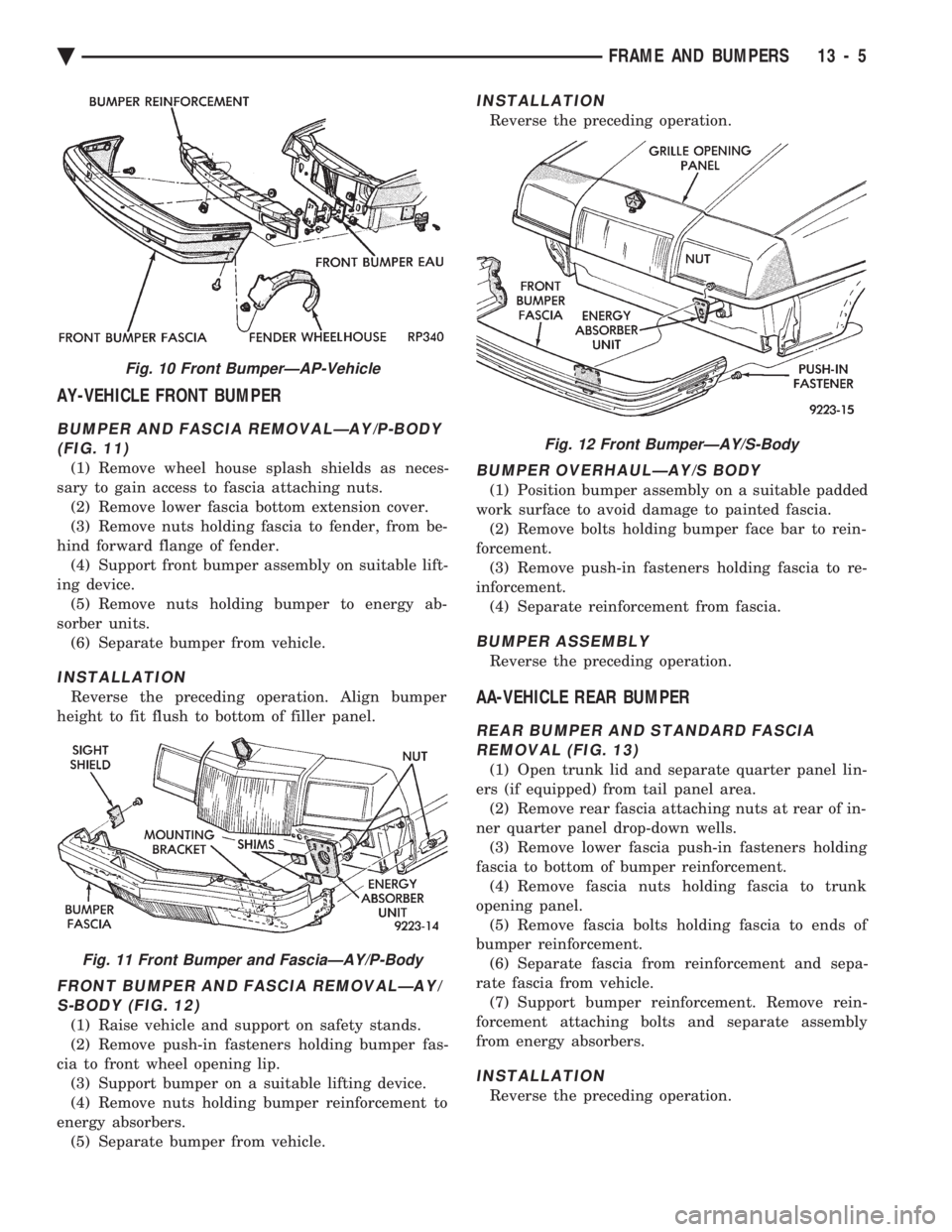
AY-VEHICLE FRONT BUMPER
BUMPER AND FASCIA REMOVALÐAY/P-BODY (FIG. 11)
(1) Remove wheel house splash shields as neces-
sary to gain access to fascia attaching nuts. (2) Remove lower fascia bottom extension cover.
(3) Remove nuts holding fascia to fender, from be-
hind forward flange of fender. (4) Support front bumper assembly on suitable lift-
ing device. (5) Remove nuts holding bumper to energy ab-
sorber units. (6) Separate bumper from vehicle.
INSTALLATION
Reverse the preceding operation. Align bumper
height to fit flush to bottom of filler panel.
FRONT BUMPER AND FASCIA REMOVALÐAY/ S-BODY (FIG. 12)
(1) Raise vehicle and support on safety stands.
(2) Remove push-in fasteners holding bumper fas-
cia to front wheel opening lip. (3) Support bumper on a suitable lifting device.
(4) Remove nuts holding bumper reinforcement to
energy absorbers. (5) Separate bumper from vehicle.
INSTALLATION
Reverse the preceding operation.
BUMPER OVERHAULÐAY/S BODY
(1) Position bumper assembly on a suitable padded
work surface to avoid damage to painted fascia. (2) Remove bolts holding bumper face bar to rein-
forcement. (3) Remove push-in fasteners holding fascia to re-
inforcement. (4) Separate reinforcement from fascia.
BUMPER ASSEMBLY
Reverse the preceding operation.
AA-VEHICLE REAR BUMPER
REAR BUMPER AND STANDARD FASCIAREMOVAL (FIG. 13)
(1) Open trunk lid and separate quarter panel lin-
ers (if equipped) from tail panel area. (2) Remove rear fascia attaching nuts at rear of in-
ner quarter panel drop-down wells. (3) Remove lower fascia push-in fasteners holding
fascia to bottom of bumper reinforcement. (4) Remove fascia nuts holding fascia to trunk
opening panel. (5) Remove fascia bolts holding fascia to ends of
bumper reinforcement. (6) Separate fascia from reinforcement and sepa-
rate fascia from vehicle. (7) Support bumper reinforcement. Remove rein-
forcement attaching bolts and separate assembly
from energy absorbers.
INSTALLATION
Reverse the preceding operation.
Fig. 10 Front BumperÐAP-Vehicle
Fig. 11 Front Bumper and FasciaÐAY/P-Body
Fig. 12 Front BumperÐAY/S-Body
Ä FRAME AND BUMPERS 13 - 5
Page 1728 of 2438
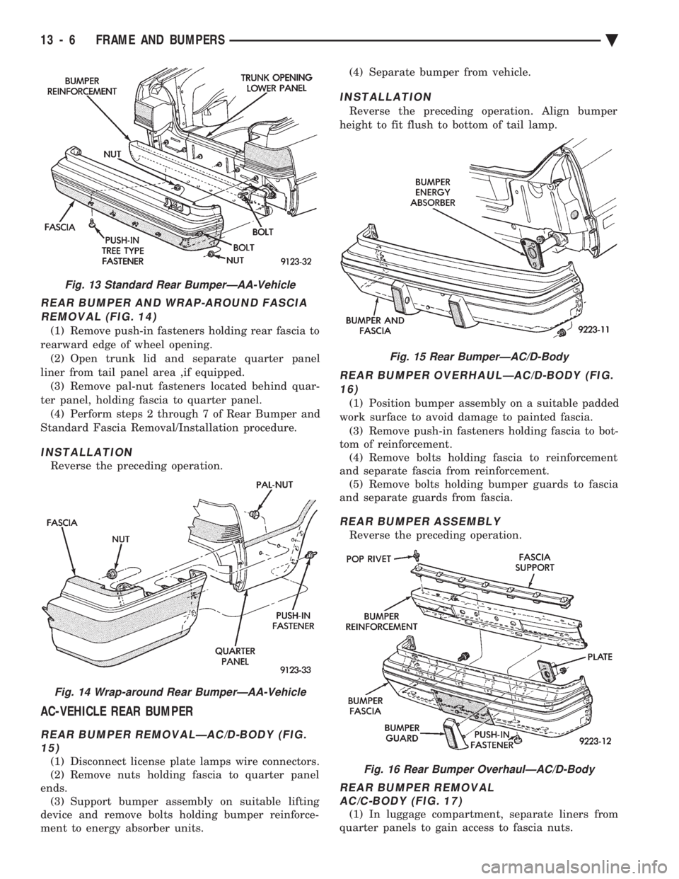
REAR BUMPER AND WRAP-AROUND FASCIA REMOVAL (FIG. 14)
(1) Remove push-in fasteners holding rear fascia to
rearward edge of wheel opening. (2) Open trunk lid and separate quarter panel
liner from tail panel area ,if equipped. (3) Remove pal-nut fasteners located behind quar-
ter panel, holding fascia to quarter panel. (4) Perform steps 2 through 7 of Rear Bumper and
Standard Fascia Removal/Installation procedure.
INSTALLATION
Reverse the preceding operation.
AC-VEHICLE REAR BUMPER
REAR BUMPER REMOVALÐAC/D-BODY (FIG. 15)
(1) Disconnect license plate lamps wire connectors.
(2) Remove nuts holding fascia to quarter panel
ends. (3) Support bumper assembly on suitable lifting
device and remove bolts holding bumper reinforce-
ment to energy absorber units. (4) Separate bumper from vehicle.
INSTALLATION
Reverse the preceding operation. Align bumper
height to fit flush to bottom of tail lamp.
REAR BUMPER OVERHAULÐAC/D-BODY (FIG. 16)
(1) Position bumper assembly on a suitable padded
work surface to avoid damage to painted fascia. (3) Remove push-in fasteners holding fascia to bot-
tom of reinforcement. (4) Remove bolts holding fascia to reinforcement
and separate fascia from reinforcement. (5) Remove bolts holding bumper guards to fascia
and separate guards from fascia.
REAR BUMPER ASSEMBLY
Reverse the preceding operation.
REAR BUMPER REMOVAL AC/C-BODY (FIG. 17)
(1) In luggage compartment, separate liners from
quarter panels to gain access to fascia nuts.
Fig. 13 Standard Rear BumperÐAA-Vehicle
Fig. 14 Wrap-around Rear BumperÐAA-Vehicle
Fig. 15 Rear BumperÐAC/D-Body
Fig. 16 Rear Bumper OverhaulÐAC/D-Body
13 - 6 FRAME AND BUMPERS Ä
Page 1730 of 2438
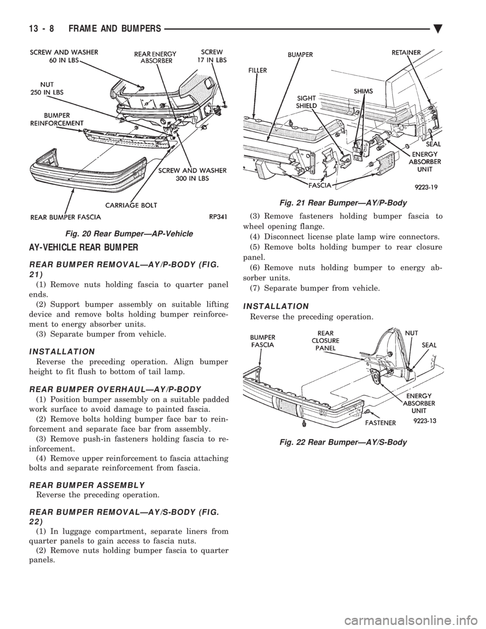
AY-VEHICLE REAR BUMPER
REAR BUMPER REMOVALÐAY/P-BODY (FIG. 21)
(1) Remove nuts holding fascia to quarter panel
ends. (2) Support bumper assembly on suitable lifting
device and remove bolts holding bumper reinforce-
ment to energy absorber units. (3) Separate bumper from vehicle.
INSTALLATION
Reverse the preceding operation. Align bumper
height to fit flush to bottom of tail lamp.
REAR BUMPER OVERHAULÐAY/P-BODY
(1) Position bumper assembly on a suitable padded
work surface to avoid damage to painted fascia. (2) Remove bolts holding bumper face bar to rein-
forcement and separate face bar from assembly. (3) Remove push-in fasteners holding fascia to re-
inforcement. (4) Remove upper reinforcement to fascia attaching
bolts and separate reinforcement from fascia.
REAR BUMPER ASSEMBLY
Reverse the preceding operation.
REAR BUMPER REMOVALÐAY/S-BODY (FIG. 22)
(1) In luggage compartment, separate liners from
quarter panels to gain access to fascia nuts. (2) Remove nuts holding bumper fascia to quarter
panels. (3) Remove fasteners holding bumper fascia to
wheel opening flange. (4) Disconnect license plate lamp wire connectors.
(5) Remove bolts holding bumper to rear closure
panel. (6) Remove nuts holding bumper to energy ab-
sorber units. (7) Separate bumper from vehicle.
INSTALLATION
Reverse the preceding operation.
Fig. 20 Rear BumperÐAP-Vehicle
Fig. 21 Rear BumperÐAY/P-Body
Fig. 22 Rear BumperÐAY/S-Body
13 - 8 FRAME AND BUMPERS Ä
Page 1731 of 2438
FRAME INDEX
page page
Crossmember ........................... 17
Frame Dimensions ........................ 9 General Information
........................ 9
GENERAL INFORMATION
In this section, references are made to Vehicle
Family (Body) codes. To determine the vehicle family
identification code, refer to the Introduction Group at
the front of this manual.
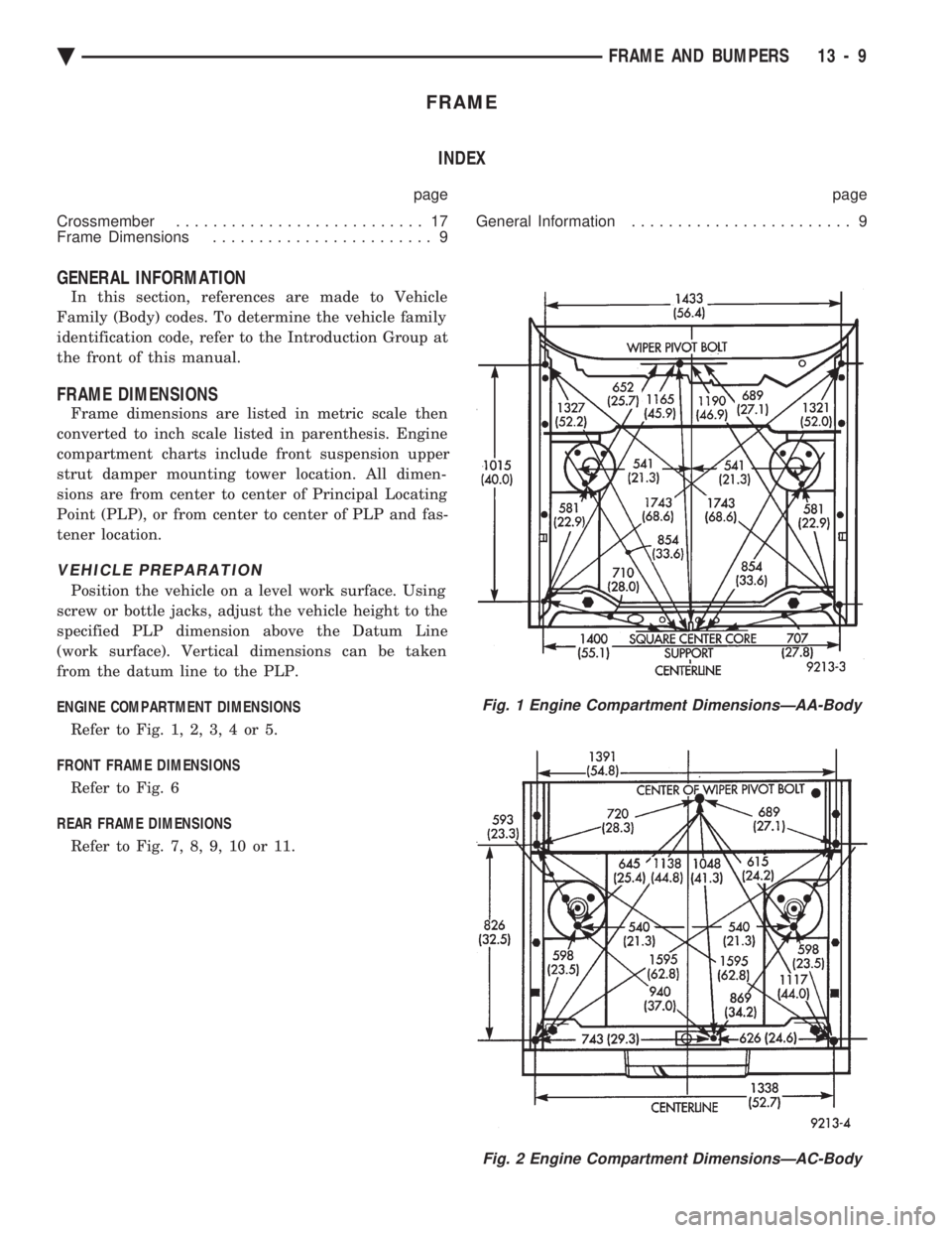
FRAME DIMENSIONS
Frame dimensions are listed in metric scale then
converted to inch scale listed in parenthesis. Engine
compartment charts include front suspension upper
strut damper mounting tower location. All dimen-
sions are from center to center of Principal Locating
Point (PLP), or from center to center of PLP and fas-
tener location.
VEHICLE PREPARATION
Position the vehicle on a level work surface. Using
screw or bottle jacks, adjust the vehicle height to the
specified PLP dimension above the Datum Line
(work surface). Vertical dimensions can be taken
from the datum line to the PLP.
ENGINE COMPARTMENT DIMENSIONS Refer to Fig. 1, 2, 3, 4 or 5.
FRONT FRAME DIMENSIONS Refer to Fig. 6
REAR FRAME DIMENSIONS Refer to Fig. 7, 8, 9, 10 or 11.
Fig. 1 Engine Compartment DimensionsÐAA-Body
Fig. 2 Engine Compartment DimensionsÐAC-Body
Ä FRAME AND BUMPERS 13 - 9