1993 CHEVROLET PLYMOUTH ACCLAIM wiring
[x] Cancel search: wiringPage 247 of 2438
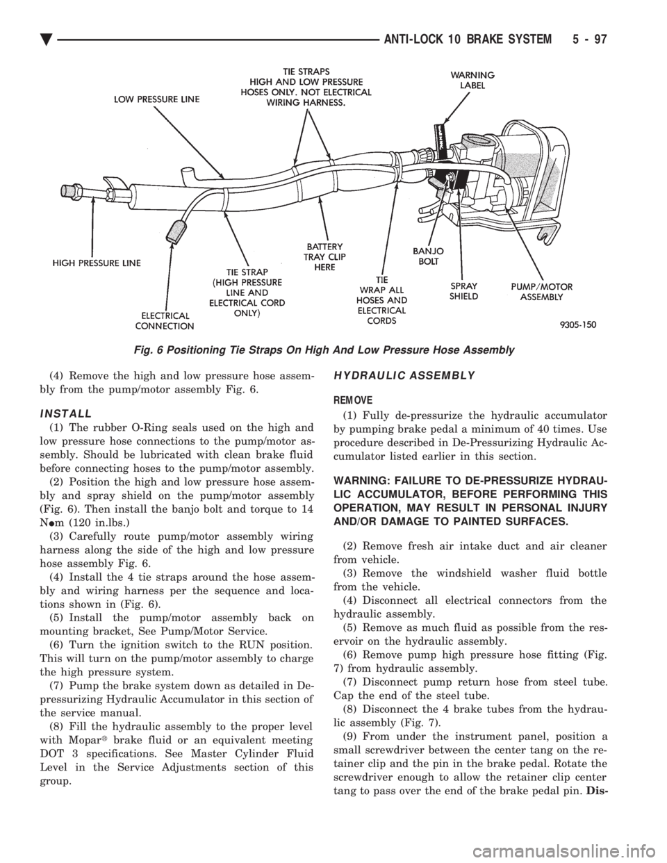
(4) Remove the high and low pressure hose assem-
bly from the pump/motor assembly Fig. 6.
INSTALL
(1) The rubber O-Ring seals used on the high and
low pressure hose connections to the pump/motor as-
sembly. Should be lubricated with clean brake fluid
before connecting hoses to the pump/motor assembly. (2) Position the high and low pressure hose assem-
bly and spray shield on the pump/motor assembly
(Fig. 6). Then install the banjo bolt and torque to 14
N Im (120 in.lbs.)
(3) Carefully route pump/motor assembly wiring
harness along the side of the high and low pressure
hose assembly Fig. 6. (4) Install the 4 tie straps around the hose assem-
bly and wiring harness per the sequence and loca-
tions shown in (Fig. 6). (5) Install the pump/motor assembly back on
mounting bracket, See Pump/Motor Service. (6) Turn the ignition switch to the RUN position.
This will turn on the pump/motor assembly to charge
the high pressure system. (7) Pump the brake system down as detailed in De-
pressurizing Hydraulic Accumulator in this section of
the service manual. (8) Fill the hydraulic assembly to the proper level
with Mopar tbrake fluid or an equivalent meeting
DOT 3 specifications. See Master Cylinder Fluid
Level in the Service Adjustments section of this
group.
HYDRAULIC ASSEMBLY
REMOVE
(1) Fully de-pressurize the hydraulic accumulator
by pumping brake pedal a minimum of 40 times. Use
procedure described in De-Pressurizing Hydraulic Ac-
cumulator listed earlier in this section.
WARNING: FAILURE TO DE-PRESSURIZE HYDRAU-
LIC ACCUMULATOR, BEFORE PERFORMING THIS
OPERATION, MAY RESULT IN PERSONAL INJURY
AND/OR DAMAGE TO PAINTED SURFACES.
(2) Remove fresh air intake duct and air cleaner
from vehicle. (3) Remove the windshield washer fluid bottle
from the vehicle. (4) Disconnect all electrical connectors from the
hydraulic assembly. (5) Remove as much fluid as possible from the res-
ervoir on the hydraulic assembly. (6) Remove pump high pressure hose fitting (Fig.
7) from hydraulic assembly. (7) Disconnect pump return hose from steel tube.
Cap the end of the steel tube. (8) Disconnect the 4 brake tubes from the hydrau-
lic assembly (Fig. 7). (9) From under the instrument panel, position a
small screwdriver between the center tang on the re-
tainer clip and the pin in the brake pedal. Rotate the
screwdriver enough to allow the retainer clip center
tang to pass over the end of the brake pedal pin. Dis-
Fig. 6 Positioning Tie Straps On High And Low Pressure Hose Assembly
Ä ANTI-LOCK 10 BRAKE SYSTEM 5 - 97
Page 253 of 2438
ELECTRONIC COMPONENTS
CONTROLLER ANTI-LOCK BRAKE (CAB)
REMOVAL (1) Turn vehicle ignition off.
(2) Raise vehicle on hoist, (CAB) access for re-
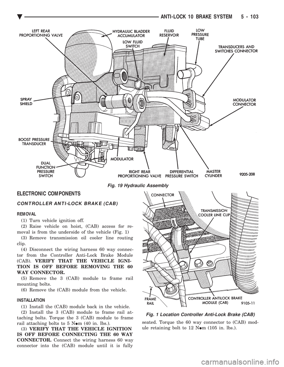
moval is from the underside of the vehicle (Fig. 1) (3) Remove transmission oil cooler line routing
clip. (4) Disconnect the wiring harness 60 way connec-
tor from the Controller Anti-Lock Brake Module
(CAB). VERIFY THAT THE VEHICLE IGNI-
TION IS OFF BEFORE REMOVING THE 60
WAY CONNECTOR. (5) Remove the 3 (CAB) module to frame rail
mounting bolts. (6) Remove the (CAB) module from the vehicle.
INSTALLATION (1) Install the (CAB) module back in the vehicle.
(2) Install the 3 (CAB) module to frame rail at-
taching bolts. Torque the 3 (CAB) module to frame
rail attaching bolts to 5 N Im (40 in. lbs.).
(3) VERIFY THAT THE VEHICLE IGNITION
IS OFF BEFORE CONNECTING THE 60 WAY
CONNECTOR. Connect the wiring harness 60 way
connector into the (CAB) module until it is fully seated. Torque the 60 way connector to (CAB) mod-
ule retaining bolt to 12 N Im (105 in. lbs.).
Fig. 19 Hydraulic Assembly
Fig. 1 Location Controller Anti-Lock Brake (CAB)
Ä ANTI-LOCK 10 BRAKE SYSTEM 5 - 103
Page 254 of 2438

SYSTEM RELAY, ANTI-LOCK WARNING LAMP RELAY AND PUMP/MOTOR RELAYS (FIG. 2)
REMOVE
See (Fig. 2) Power Distribution Center. Find the lo-
cation of the pump/motor relay in the (PDC). Remove
pump/motor relay by pulling upward and install by
pushing firmly into position. Do not twist the relay
when removing or installing it. See (Fig. 10) in the Relay And Warning Lamp Sec-
tion of this group, for the location of the Anti-Lock
system relay and the Yellow Lamp relay. Remove
the relay from the vehicle using the following proce-
dure. (1) Disconnect the wiring harness connectors from
the relays. Connectors are removed from the relays
by disengaging the connector locking tab from relay
and pulling strait off relay, do not twist. (2) Then remove the relay pack to inner fender at-
taching bolt.
INSTALL The Anti-Lock system and Yellow Lamp relay are
installed using the following procedure. (1) Mount the relay pack to the inner fender with
the anti-rotation tab on the bracket around lip of in-
ner fender hole (Fig. 10). (2) Install the relay pack to inner fender mounting
bolt and torque to 4 N Im (35 in. lbs.). (3) Connect the wiring harness connectors onto the
relays until the locking tabs on the connectors and
relays are fully engaged. Do not twist connectors when
installing them on the relays.
WHEEL SPEED SENSORS
INSPECTION
Inspect tone wheels (Fig. 3) for any missing or broken
teeth, this can cause erratic speed sensor signals.
Tone wheels should show no evidence of contact with
the wheel speed sensor. If contact was made, determine
cause and correct. Excessive runout of the tone wheels can cause erratic
wheel speed sensor signals. Replace assembly if runout
exceeds approximately 0.25 mm (0.010 inch).
FRONT WHEEL SPEED SENSOR
REMOVAL
(1) Raise vehicle and remove front wheel and tire
assembly. (2) Remove screw from clip (Fig. 4) that holds sensor
assembly grommet into fender shield. (3) Carefully, pull sensor assembly grommet from
fender shield. When removing grommet from
fender shield, do not pull on speed sensor cable. (4) Unplug speed sensor cable connector, from ve-
hicle wiring harness. (5) Remove the 2 screws (Fig. 4) that secure the
speed sensor cable, routing tube to the fender well. (6) Remove the 2 sensor assembly grommets from
the retainer bracket, on the strut damper (Fig. 4). (7) Remove speed sensor assembly to steering
knuckle attaching bolt (Fig. 4). (8) Carefully, remove sensor head from steering
knuckle. If the sensor has seized, due to corrosion, use
a hammer and punch to tap edge of sensor ear
Fig. 2 Pump/Motor and Anti-Lock System Relays
Fig. 3 Tone Wheel (Typical)
5 - 104 ANTI-LOCK 10 BRAKE SYSTEM Ä
Page 255 of 2438
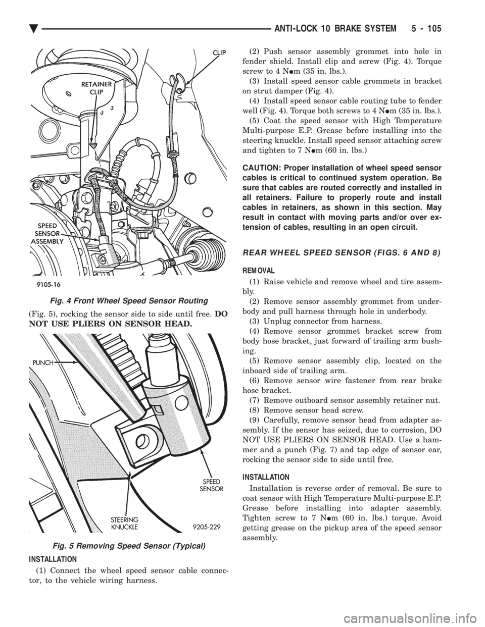
(Fig. 5), rocking the sensor side to side until free. DO
NOT USE PLIERS ON SENSOR HEAD.
INSTALLATION (1) Connect the wheel speed sensor cable connec-
tor, to the vehicle wiring harness. (2) Push sensor assembly grommet into hole in
fender shield. Install clip and screw (Fig. 4). Torque
screw to 4 N Im (35 in. lbs.).
(3) Install speed sensor cable grommets in bracket
on strut damper (Fig. 4). (4) Install speed sensor cable routing tube to fender
well (Fig. 4). Torque both screws to 4 N Im (35 in. lbs.).
(5) Coat the speed sensor with High Temperature
Multi-purpose E.P. Grease before installing into the
steering knuckle. Install speed sensor attaching screw
and tighten to 7 N Im (60 in. lbs.)
CAUTION: Proper installation of wheel speed sensor
cables is critical to continued system operation. Be
sure that cables are routed correctly and installed in
all retainers. Failure to properly route and install
cables in retainers, as shown in this section. May
result in contact with moving parts and/or over ex-
tension of cables, resulting in an open circuit.
REAR WHEEL SPEED SENSOR (FIGS. 6 AND 8)
REMOVAL
(1) Raise vehicle and remove wheel and tire assem-
bly. (2) Remove sensor assembly grommet from under-
body and pull harness through hole in underbody. (3) Unplug connector from harness.
(4) Remove sensor grommet bracket screw from
body hose bracket, just forward of trailing arm bush-
ing. (5) Remove sensor assembly clip, located on the
inboard side of trailing arm. (6) Remove sensor wire fastener from rear brake
hose bracket. (7) Remove outboard sensor assembly retainer nut.
(8) Remove sensor head screw.
(9) Carefully, remove sensor head from adapter as-
sembly. If the sensor has seized, due to corrosion, DO
NOT USE PLIERS ON SENSOR HEAD. Use a ham-
mer and a punch (Fig. 7) and tap edge of sensor ear,
rocking the sensor side to side until free.
INSTALLATION
Installation is reverse order of removal. Be sure to
coat sensor with High Temperature Multi-purpose E.P.
Grease before installing into adapter assembly.
Tighten screw to 7 N Im (60 in. lbs.) torque. Avoid
getting grease on the pickup area of the speed sensor
assembly.
Fig. 4 Front Wheel Speed Sensor Routing
Fig. 5 Removing Speed Sensor (Typical)
Ä ANTI-LOCK 10 BRAKE SYSTEM 5 - 105
Page 256 of 2438

DUAL FUNCTION PRESSURE SWITCH
REMOVE
WARNING: FAILURE TO DE-PRESSURIZE THE HY-
DRAULIC ACCUMULATOR PRIOR TO REMOVING
DUAL FUNCTION PRESSURE SWITCH. WILL RESULT
IN PERSONAL INJURY AND/OR DAMAGE TO
PAINTED SURFACES OF THE VEHICLE. CAUTION: THOROUGHLY CLEAN THE BOTTOM OF
THE HYDRAULIC ASSEMBLY IN THE AREA OF THE
DUAL FUNCTION PRESSURE SWITCH, BEFORE RE-
MOVING THE SWITCH FROM HYDRAULIC ASSEM-
BLY. USE MOPAR BRAKE PARTS CLEANER OR AN
EQUIVALENT. EXTREME CARE MUST BE USED SO
NO DIRT IS ALLOWED TO ENTER THE HYDRAULIC
ASSEMBLY THROUGH WHERE THE DUAL FUNC-
TION PRESSURE SWITCH IS MOUNTED. ANY DIRT
ENTERING HYDRAULIC ASSEMBLY MAY PLUG IN-
TERNAL PASSAGES CAUSING A HYDRAULIC AS-
SEMBLY FAILURE.
(1) Fully de-pressurize the hydraulic accumulator by
pumping brake pedal a minimum of 40 times. Use
procedure described in De-Pressurizing Hydraulic Ac-
cumulator listed earlier in this section. (2) Raise vehicle See Hoisting, Group 0.
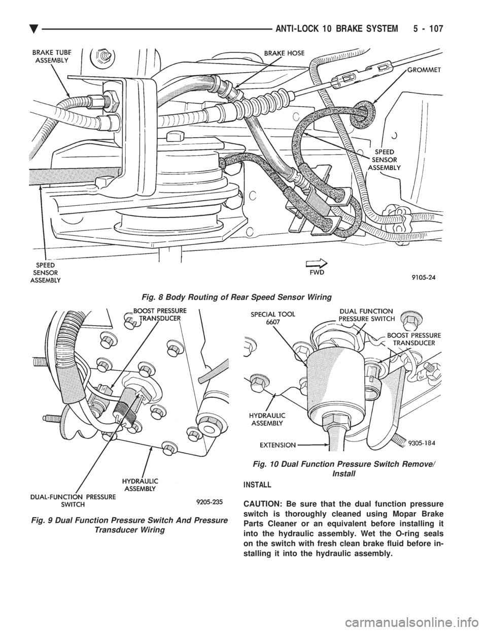
(3) From under vehicle, disconnect wiring harness
connectors from dual function pressure switch and
boost pressure transducer (Fig. 9) on the bottom of
hydraulic assembly.
WARNING: WEAR EYE PROTECTION WHEN PER-
FORMING THE FOLLOWING PROCEDURE. SERIOUS
EYE INJURY CAN RESULT FROM BRAKE FLUID
CONTACTING THE EYES.
(4) Be sure that the hydraulic system is de-
pressurized. Remove the dual function pressure
switch from the hydraulic assembly using Socket,
Special Tool 6607 (Fig. 10). Access to the switch is from
under the vehicle using a long extension.
Fig. 6 Rear Wheel Speed Sensor Routing at Trailing Arm
Fig. 7 Removing Speed Sensor (Typical)
5 - 106 ANTI-LOCK 10 BRAKE SYSTEM Ä
Page 257 of 2438
INSTALL
CAUTION: Be sure that the dual function pressure
switch is thoroughly cleaned using Mopar Brake
Parts Cleaner or an equivalent before installing it
into the hydraulic assembly. Wet the O-ring seals
on the switch with fresh clean brake fluid before in-
stalling it into the hydraulic assembly.
Fig. 8 Body Routing of Rear Speed Sensor Wiring
Fig. 9 Dual Function Pressure Switch And Pressure Transducer Wiring
Fig. 10 Dual Function Pressure Switch Remove/ Install
Ä ANTI-LOCK 10 BRAKE SYSTEM 5 - 107
Page 258 of 2438

CAUTION: Do not insert dual function pressure
switch into hydraulic assembly using the socket
and ratchet. Cross threading of the switch may oc-
cur. (1) Install the dual function pressure switch into
the hydraulic assembly by hand until the O-ring
seals are seated. (2) Using Socket, Special Tool 6607, (Fig. 10)
torque the dual function pressure switch into the hy-
draulic assembly to 12 N Im (9 ft. lbs.).
(3) Connect the wiring harness connectors (Fig. 9)
onto the dual function pressure switch and the boost
pressure transducer. Be sure the locking tabs on the
connectors are fully engaged on the switches. (4) Lower the vehicle.
(5) Turn the ignition switch to the on position and
let the system pressurize. Check for any leaks at the
dual function pressure switch. (6) Fully de-pressurize the hydraulic assembly a
second time. This will purge any air out that may
have entered hydraulic assembly when the switch
was removed. Turn the ignition switch to the on po-
sition and let the system pressurize again. (7) Road test vehicle to insure that the brake sys-
tem is performing correctly.
PRIMARY PRESSURE TRANSDUCER
REMOVE
WARNING: FAILURE TO FULLY DE-PRESSURIZE
THE HYDRAULIC BLADDER ACCUMULATOR PRIOR
TO REMOVING PRIMARY PRESSURE TRANS-
DUCER. WILL RESULT IN PERSONAL INJURY
AND/OR DAMAGE TO PAINTED SURFACES OF THE
VEHICLE.
To remove primary pressure transducer (Fig. 11),
from hydraulic assembly, removal of hydraulic as-
sembly from vehicle is notrequired.
(1) Fully de-pressurize the hydraulic accumulator
by pumping brake pedal a minimum of 40 times. Use
procedure described in De-Pressurizing Hydraulic Ac-
cumulator listed earlier in this section. (2) Remove as much brake fluid as possible from
the brake fluid reservoir, using a syringe or equiva-
lent method. (3) Using oil filter band wrench, Special Tool
C-4065 or equivalent, (Fig. 12) loosen bladder accu-
mulator. Then remove bladder accumulator and
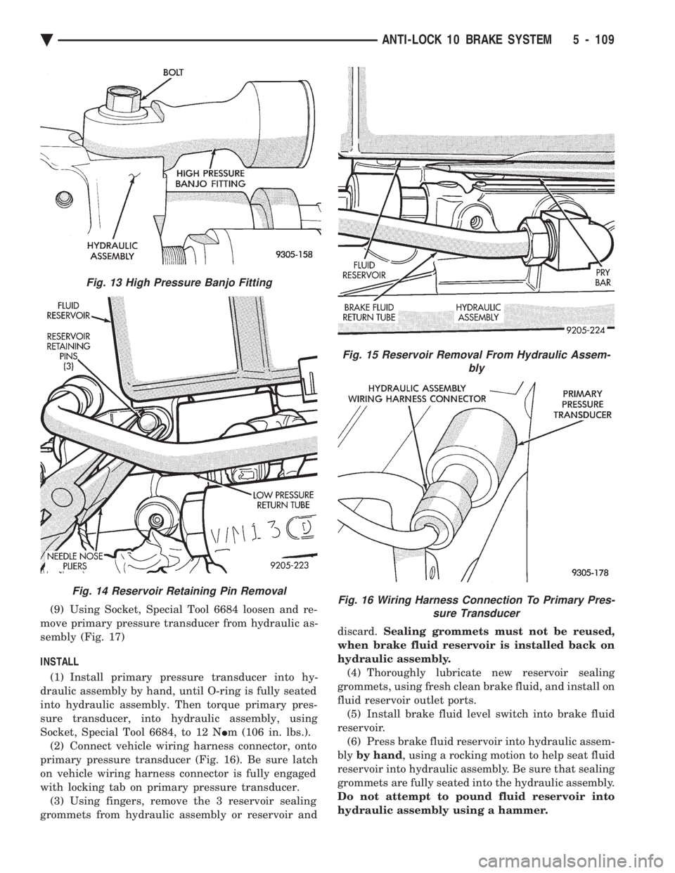
brake fluid spray shield from hydraulic assembly. (4) Remove high pressure banjo fitting (Fig. 13)
from hydraulic assembly. (5) Using needle nose pliers, remove the 3 fluid
reservoir retaining pins from the hydraulic assembly
(Fig. 14). Compress barb on opposite side of retaining
pin, to prevent pin from breaking. CAUTION: Be extremely careful during the following
procedure to avoid damaging or puncturing brake
fluid reservoir during its removal.
(6) Remove brake fluid reservoir from hydraulic
assembly by carefullyprying between reservoir and
hydraulic assembly using a blunt pry bar (Fig. 15).
Use a rocking motion to help disengage reservoir
from grommets while prying. (7) Remove brake fluid level sensor from reservoir
and remove fluid reservoir from vehicle. (8) Remove hydraulic assembly wiring harness
connector from the primary pressure transducer (Fig.
16).
Fig. 11 Primary Pressure Transducer Location On Hydraulic Assembly
Fig. 12 Removing Bladder Accumulator
5 - 108 ANTI-LOCK 10 BRAKE SYSTEM Ä
Page 259 of 2438
(9) Using Socket, Special Tool 6684 loosen and re-
move primary pressure transducer from hydraulic as-
sembly (Fig. 17)
INSTALL
(1) Install primary pressure transducer into hy-
draulic assembly by hand, until O-ring is fully seated
into hydraulic assembly. Then torque primary pres-
sure transducer, into hydraulic assembly, using
Socket, Special Tool 6684, to 12 N Im (106 in. lbs.).
(2) Connect vehicle wiring harness connector, onto
primary pressure transducer (Fig. 16). Be sure latch
on vehicle wiring harness connector is fully engaged
with locking tab on primary pressure transducer. (3) Using fingers, remove the 3 reservoir sealing
grommets from hydraulic assembly or reservoir and discard.
Sealing grommets must not be reused,
when brake fluid reservoir is installed back on
hydraulic assembly. (4) Thoroughly lubricate new reservoir sealing
grommets, using fresh clean brake fluid, and install on
fluid reservoir outlet ports. (5) Install brake fluid level switch into brake fluid
reservoir. (6) Press brake fluid reservoir into hydraulic assem-
bly by hand , using a rocking motion to help seat fluid
reservoir into hydraulic assembly. Be sure that sealing
grommets are fully seated into the hydraulic assembly.
Do not attempt to pound fluid reservoir into
hydraulic assembly using a hammer.
Fig. 13 High Pressure Banjo Fitting
Fig. 14 Reservoir Retaining Pin Removal
Fig. 15 Reservoir Removal From Hydraulic Assem- bly
Fig. 16 Wiring Harness Connection To Primary Pres-sure Transducer
Ä ANTI-LOCK 10 BRAKE SYSTEM 5 - 109