1993 CHEVROLET PLYMOUTH ACCLAIM wiring
[x] Cancel search: wiringPage 328 of 2438

INSTALL (1) Install CAB and system relay/bracket assembly
on CAB mounting bracket (Fig. 4). Install the 3 CAB
to CAB mounting bracket attaching screws (Fig. 4). Torque the 3 CAB to mounting bracket attaching
screws to 12 N Im (106 in. lbs.).
(2) Install the CAB, system relay and mounting
bracket on the frame rail of the vehicle. Install the 2
bolts (Fig. 3) attaching the CAB mounting bracket to
the frame rail of the vehicle. Torque the 2 CAB mount-
ing bracket attaching bolts (Fig. 3) to 28 N Im (250 in.
lbs.).
CAUTION: BEFORE INSTALLING 60 WAY CONNEC-
TOR ON THE CAB VERIFY THAT THE VEHICLE'S
IGNITION IS IN THE OFF OR LOCK POSITION. IF
IGNITION IS ON WHEN 60 WAY CONNECTOR IS
INSTALLED ON THE CAB, DAMAGE TO THE CON-
TROLLER COULD OCCUR.
(3) Install the wiring harness 60 way connector (Fig.
2) into the CAB electrical connector as far as possible
by hand. After 60 way connector is installed as far as
possible by hand, use the 60 way connector retaining
bolt (Fig. 2) to fully seat connector into the CAB. Then
torque the wiring harness 60 way CAB connector
retaining bolt to 4 N Im (38 in. lbs.).
(4) Install the wiring harness connector onto the
Antilock system relay (Fig. 1). Be sure locking tab
on wiring harness connector is fully engaged
with lock on system relay. (5) Road test vehicle to verify correct operation of the
vehicles's Antilock brake system.
REMOVAL/INSTALLATION OF SYSTEM RELAY
The antilock brake system, system relay is serviced
as an assembly, with the mounting bracket. The sys-
tem relay is mounted to a separate bracket which is
attached to the CAB and mounting bracket assembly
(Fig. 5).
Fig. 2 CAB 60 Way Connector And Retaining Bolt
Fig. 3 CAB Bracket To Frame Rail Mounting Bolts
Fig. 4 CAB Removal From Mounting Bracket
Fig. 5 Antilock Brakes System Relay Location
5 - 42 ANTILOCK 4 BRAKE SYSTEM Ä
Page 329 of 2438

REMOVE (1) Hold system relay with one hand, while pulling
strait down on the wiring harness connector. Until
connector is free from the relay (do not twist the
connector). (2) Remove screw (Fig. 6) holding the system relay
and bracket to the CAB bracket. Then remove the
system relay and mounting bracket assembly from
the CAB bracket.
INSTALL (1) Mount the system relay and its mounting
bracket assembly to the CAB mounting bracket, with
the mounting screw (Fig. 6). (2) Holding the system relay with one hand, push-
ing the wiring harness connector strait onto the ter-
minals of the relay. Make sure connector is fully
seated onto terminals of the system relay and the
lock on the wiring harness connector is fully engaged
with the relay. (3) Road test vehicle to verify correct operation of
the vehicles's Antilock brake system.
REMOVE/INSTALL PUMP MOTOR RELAY
Find location of Antilock Pump Motor Relay (Fig. 7
& 8), depending on whether the vehicle being ser-
viced has or does not have a power distribution cen-
ter PDC. (1) Hold the Antilock pump motor relay with one
hand, while pulling wiring harness relay connector
strait off the relay terminals. (2) Remove the pump motor relay assembly from
the vehicle. (3) Installation is done in the reverse order off re-
moval. Be sure that the wiring harness connector is
fully seated onto the terminals of the Pump Motor
Relay.
WHEEL SPEED SENSORS
INSPECTION
Inspect tonewheel for missing or broken teeth, this
can cause erratic sensor signals. Tonewheel should show no evidence of contact with
the wheel speed sensor. If contact was made, deter-
mine cause and correct. Excessive runout of the tonewheel can cause er-
ratic wheel speed sensor. Replace assembly if runout
exceeds approximately 0.25 mm (0.010 inch).
FRONT WHEEL SPEED SENSOR (FIG. 9)
REMOVAL
(1) Raise vehicle and remove wheel and tire as-
sembly. (2) Remove screw from grommet retainer clip that
holds the grommet into fender shield (Fig. 9). (3) Remove the 2 screws that fasten the sensor
routing tube to the frame rail.
Fig. 6 System Relay And Bracket Removal
Fig. 7 Pump Motor Relay Location On AA Body W/O Power Distribution Center
Fig. 8 Pump Motor Relay Location On AJ Body WithPower Distribution Center
Ä ANTILOCK 4 BRAKE SYSTEM 5 - 43
Page 330 of 2438

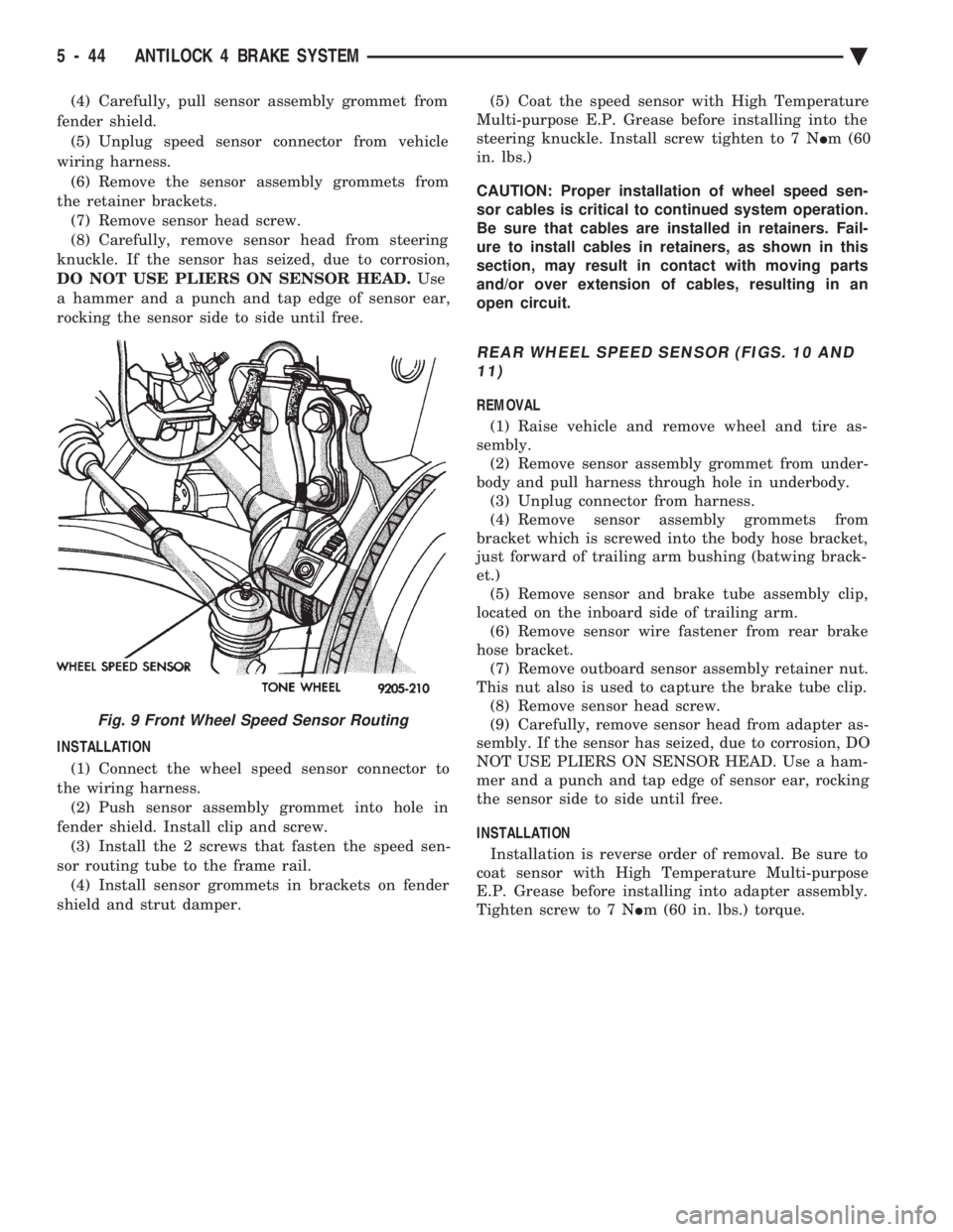
(4) Carefully, pull sensor assembly grommet from
fender shield. (5) Unplug speed sensor connector from vehicle
wiring harness. (6) Remove the sensor assembly grommets from
the retainer brackets. (7) Remove sensor head screw.
(8) Carefully, remove sensor head from steering
knuckle. If the sensor has seized, due to corrosion,
DO NOT USE PLIERS ON SENSOR HEAD. Use
a hammer and a punch and tap edge of sensor ear,
rocking the sensor side to side until free.
INSTALLATION
(1) Connect the wheel speed sensor connector to
the wiring harness. (2) Push sensor assembly grommet into hole in
fender shield. Install clip and screw. (3) Install the 2 screws that fasten the speed sen-
sor routing tube to the frame rail. (4) Install sensor grommets in brackets on fender
shield and strut damper. (5) Coat the speed sensor with High Temperature
Multi-purpose E.P. Grease before installing into the
steering knuckle. Install screw tighten to 7 N Im (60
in. lbs.)
CAUTION: Proper installation of wheel speed sen-
sor cables is critical to continued system operation.
Be sure that cables are installed in retainers. Fail-
ure to install cables in retainers, as shown in this
section, may result in contact with moving parts
and/or over extension of cables, resulting in an
open circuit.
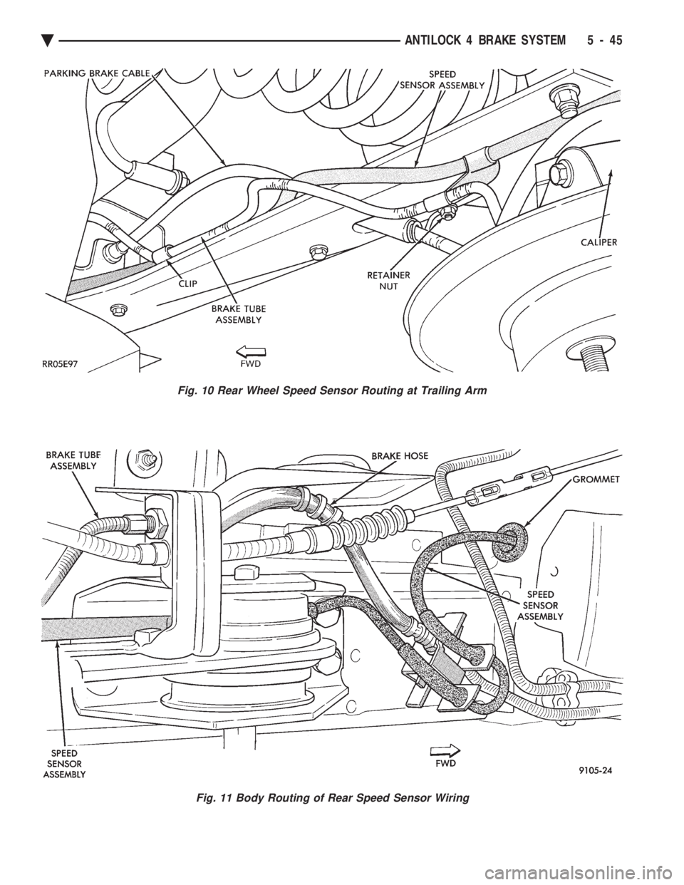
REAR WHEEL SPEED SENSOR (FIGS. 10 AND 11)
REMOVAL
(1) Raise vehicle and remove wheel and tire as-
sembly. (2) Remove sensor assembly grommet from under-
body and pull harness through hole in underbody. (3) Unplug connector from harness.
(4) Remove sensor assembly grommets from
bracket which is screwed into the body hose bracket,
just forward of trailing arm bushing (batwing brack-
et.) (5) Remove sensor and brake tube assembly clip,
located on the inboard side of trailing arm. (6) Remove sensor wire fastener from rear brake
hose bracket. (7) Remove outboard sensor assembly retainer nut.
This nut also is used to capture the brake tube clip. (8) Remove sensor head screw.
(9) Carefully, remove sensor head from adapter as-
sembly. If the sensor has seized, due to corrosion, DO
NOT USE PLIERS ON SENSOR HEAD. Use a ham-
mer and a punch and tap edge of sensor ear, rocking
the sensor side to side until free.
INSTALLATION Installation is reverse order of removal. Be sure to
coat sensor with High Temperature Multi-purpose
E.P. Grease before installing into adapter assembly.
Tighten screw to 7 N Im (60 in. lbs.) torque.
Fig. 9 Front Wheel Speed Sensor Routing
5 - 44 ANTILOCK 4 BRAKE SYSTEM Ä
Page 331 of 2438

Fig. 11 Body Routing of Rear Speed Sensor Wiring
Fig. 10 Rear Wheel Speed Sensor Routing at Trailing Arm
Ä ANTILOCK 4 BRAKE SYSTEM 5 - 45
Page 336 of 2438

CLUTCH PEDAL POSITION SWITCH
The clutch pedal position switch functions as a
safety interlock device. It prevents possible engine
cranking with the clutch engaged. The clutch pedal position switch is wired in series
between the starter relay coil and the ignition
switch. The clutch pedal position switch is mounted to a
bracket located next to the clutch pedal. The switch
is held in place by four plastic wing tabs. The clutch pedal position switch has an adjustable
striker plate. The striker plate is located on the left
side of the clutch pedal (Fig. 3).
DIAGNOSIS
Disconnect clutch pedal position switch harness
from instrument panel wiring harness. Using a ohm
meter, check for continuity between the two termi-
nals in the connector on the switch harness. There
should be no continuity between the terminals when
the switch is in its neutral (fully extended) position.
When the switch is depressed more than 1.25 mm
(0.050) the ohm meter should show continuity. If all ohm meter readings are correct and the
switch does not operate correctly, adjustment is re-
quired. Refer to Switch Adjustment Procedure to ad-
just switch.
REMOVAL
(1) Disconnect electrical harness to switch connec-
tor. (2) Depress wing tabs on switch and push switch out
of mounting bracket. Then slide wires through slot in
bracket.
INSTALLATION
(1) Slide switch wires through slot in switch bracket.
(2) Line up switch tab with slot in switch bracket
and push switch into position. Do not pull on the switch
wires to seat switch into bracket, switch damage may
occur. (3) After installation, the switch must be adjusted
and checked for proper operation. Refer to Switch
Adjustment Procedure.
ADJUSTMENT PROCEDURE
When performing switch adjustment, the floor mat
should be removed before beginning adjustment proce-
dures. (1) Set the park brake.
(2) Disconnect clutch cable at the transaxle end of
the cable. (3) Depress clutch pedal, loosen adjusting nut and
slide the striker plate forward to fully compress the
clutch pedal position switch plunger. (4) Tighten adjusting nut to 12 N Im (105 in. lbs.).
(5) Reconnect clutch cable.
The clutch pedal position switch is now ad-
justed. A final check is required to insure that the
switch is ``made'' below the clutch release point. (1) With the park brake set and the vehicle IN
NEUTRAL turn the key to the start position. The
vehicle should not crank. If the vehicle cranks do
not continue with this test. Recheck the switch and
switch adjustment to determine the cause. If the ve-
hicle does not crank proceed to step 2. (2) With the park brake set and the vehicle IN
GEAR turn the key to the start position.
WARNING: BEFORE PERFORMING STEP THREE BE
SURE THAT THE AREA IN FRONT OF THE VEHICLE
IS CLEAR OF OBSTRUCTIONS AND PEOPLE. VE-
HICLE MAY MOVE WHEN PERFORMING THIS TEST.
(3) Slowly depress the clutch pedal and feel for any
vehicle motion when the starter is energized. If there is
no motion the switch is properly adjusted. If motion is
felt, repeat the adjustment procedure.
Fig. 3 Clutch Pedal Position Switch and Components
6 - 4 MANUAL TRANSAXLE CLUTCH Ä
Page 363 of 2438

RADIATOR HOSES
The hoses are removed using Constant Tension
Clamp pliers to compress hose clamp. A hardened, cracked, swollen or restricted hose
should be replaced. Do not damage radiator inlet and
outlet when loosening hoses. Radiator hoses should be routed without any kinks
and indexed as designed. The use of molded hoses is
recommended. Spring type hose clamps are used in all applica-
tions. If replacement is necessary replace with the
original style spring type clamp.
FANS
All models use electric motor driven cooling system
fans. The fan modules include a motor support which
may (depending on model) include a shroud. The
module is fastened to the radiator by screws with
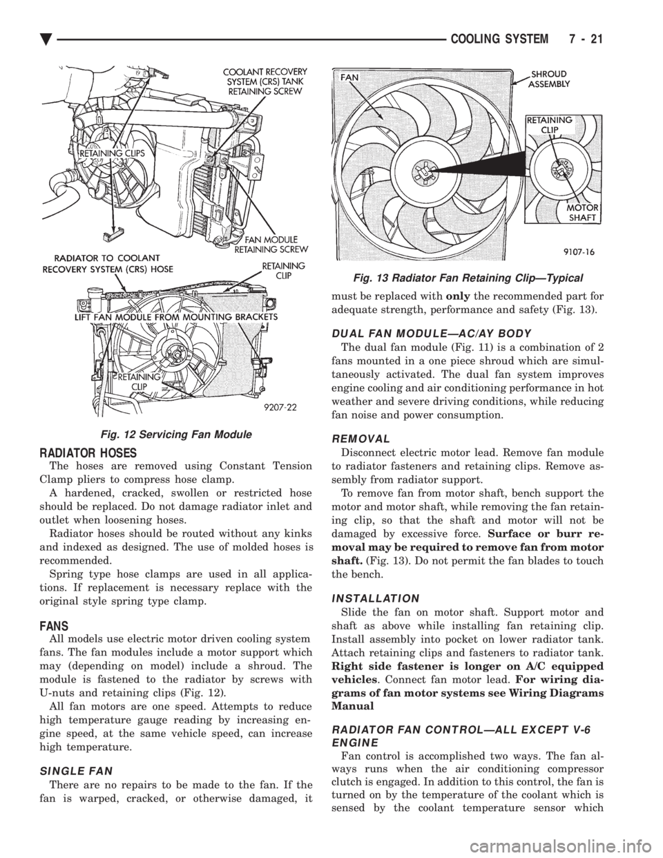
U-nuts and retaining clips (Fig. 12). All fan motors are one speed. Attempts to reduce
high temperature gauge reading by increasing en-
gine speed, at the same vehicle speed, can increase
high temperature.
SINGLE FAN
There are no repairs to be made to the fan. If the
fan is warped, cracked, or otherwise damaged, it must be replaced with
onlythe recommended part for
adequate strength, performance and safety (Fig. 13).
DUAL FAN MODULEÐAC/AY BODY
The dual fan module (Fig. 11) is a combination of 2
fans mounted in a one piece shroud which are simul-
taneously activated. The dual fan system improves
engine cooling and air conditioning performance in hot
weather and severe driving conditions, while reducing
fan noise and power consumption.
REMOVAL
Disconnect electric motor lead. Remove fan module
to radiator fasteners and retaining clips. Remove as-
sembly from radiator support. To remove fan from motor shaft, bench support the
motor and motor shaft, while removing the fan retain-
ing clip, so that the shaft and motor will not be
damaged by excessive force. Surface or burr re-
moval may be required to remove fan from motor
shaft. (Fig. 13). Do not permit the fan blades to touch
the bench.
INSTALLATION
Slide the fan on motor shaft. Support motor and
shaft as above while installing fan retaining clip.
Install assembly into pocket on lower radiator tank.
Attach retaining clips and fasteners to radiator tank.
Right side fastener is longer on A/C equipped
vehicles . Connect fan motor lead. For wiring dia-
grams of fan motor systems see Wiring Diagrams
Manual
RADIATOR FAN CONTROLÐALL EXCEPT V-6 ENGINE
Fan control is accomplished two ways. The fan al-
ways runs when the air conditioning compressor
clutch is engaged. In addition to this control, the fan is
turned on by the temperature of the coolant which is
sensed by the coolant temperature sensor which
Fig. 12 Servicing Fan Module
Fig. 13 Radiator Fan Retaining ClipÐTypical
Ä COOLING SYSTEM 7 - 21
Page 364 of 2438

sends the message to the Engine Controller. The En-
gine Controller turns on the fan through the fan re-
lay. See Wiring Diagrams Manual for circuity and
diagnostics provided.Switching through the Engine Controller provides
fan control for the following conditions.
² The fan will not run during cranking until the en-
gine starts no matter what the coolant temperature
is.
² Fan will run when the air conditioning clutch is
engaged and low pressure cutout switch is closed.
² For 4 cylinder application the fan will run at ve-
hicle speeds above about 40 mph only if coolant tem-
perature reaches 110ÉC (230ÉF). It will turn off when
the temperature drops to 104ÉC (220ÉF). At speeds
below 40 mph the fan switches on at 102ÉC (215ÉF)
and off at 93ÉC (200ÉF).
² This is to help prevent steaming. The fan will run
only below 16ÉC (60ÉF) ambient. Between 38ÉC
(100ÉF) to 97ÉC (195ÉF) coolant temperature, at idle
and then only for three minutes.
RADIATOR FAN CONTROLÐAC/AY BODY V-6 ONLY
For this application, fan control is accomplished
based on coolant temperature, and on A/C head pres-
sure. These vehicles receive the variable displace-
ment compressor. The fan will go on when;
² Coolant temperature reaches 102ÉC (215ÉF) and off
at 93.4ÉC (200ÉF) regardless of vehicle speed.
² When the head pressure reaches 1516.9 kPa (220
psi) and turn off when the pressure reaches 1103 kPa
(160 psi).
TEMPERATURE GAUGE INDICATION
At idle the temperature gauge will rise slowly to
about 5/8 gauge travel. The fan will come on and the
gauge will drop to about 1/2 gauge travel, this is nor-
mal.
ELECTRIC FAN MOTOR
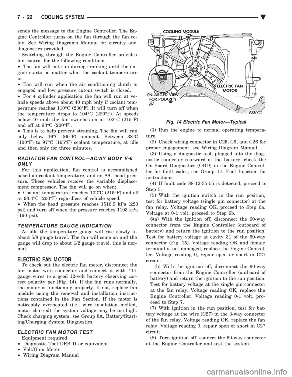
To check out the electric fan motor, disconnect the
fan motor wire connector and connect it with #14
gauge wires to a good 12-volt battery observing cor-
rect polarity per (Fig. 14). If the fan runs normally,
the motor is functioning properly. If not, replace fan
module using the removal and installation instruc-
tions contained in the Fan Section. If the motor is
noticeably overheated (i.e.; wire insulation melted,
motor charred) the system voltage may be too high.
Check charging system, see Group 8A, Battery/Start-
ing/Charging System Diagnostics.
ELECTRIC FAN MOTOR TEST
Equipment required
² Diagnostic Tool DRB II or equivalent
² Volt/Ohm Meter
² Wiring Diagram Manual (1) Run the engine to normal operating tempera-
ture. (2) Check wiring connector in C25, C9, and C26 for
proper engagement, see Wiring Diagram Manual (3) Using a diagnostic tool, plugged into the diag-
nostic connector rearward of the battery, check the
On-Board Diagnostics (OBD) in the Engine Control-
ler for fault codes, see Group 14, Fuel Injection for
instructions. (4) If fault code 88-12-35-55 is detected, proceed to
Step 5. (5) With the ignition switch in the run position,
test for battery voltage (single pin connector) at the
fan relay. Voltage reading OK, proceed to Step 6a.
Voltage at 0-1 volt, proceed to Step 6b. 6(a) With the ignition off, disconnect the 60-way
connector from the Engine Controller (outboard of
battery) and return the ignition to the run position.
Test for battery voltage at cavity 31 of the 60-way
connector (Fig. 15). Voltage reading OK and female
terminal is not damaged, replace the Engine Control-
ler. Voltage reading 0, repair open or short in C27
circuit. (b) With the ignition off, disconnect the 60-way
connector from the Engine Controller (outboard of
battery) and return the ignition to the run position.
Test for battery voltage at the single pin connector
at the fan relay. Voltage reading OK, replace the
Engine Controller. Voltage reading 0-1 volt, pro-
ceed to Step 7.
(7) With ignition in the run position, test for bat-
tery voltage at the wire (C27) in the 3-way connector
of the fan relay. Voltage reading OK, replace the fan
relay. Voltage reading 0, repair open or short in C27
circuit. (8) Turn ignition off, connect the 60-way connector
at the Engine Controller and test the system.
Fig. 14 Electric Fan MotorÐTypical
7 - 22 COOLING SYSTEM Ä
Page 373 of 2438

BATTERY/STARTING/CHARGING SYSTEMS DIAGNOSTICS
CONTENTS
page page
BATTERY TEST PROCEDURES ON-VEHICLE . . 3
FAULT CODESÐON BOARD DIAGNOSTICS . . 23
GENERAL INFORMATION .................. 1
GENERATOR TEST PROCEDURES ON VEHICLE.19 IGNITION OFF DRAW (IOD)
............... 9
SPECIFICATIONS ....................... 28
STARTER TEST PROCEDURES ON VEHICLE . 11
GENERAL INFORMATION
² For Battery, Starter or Generator replacement re-
fer to Group 8B, Battery/Starter/Generator Service.
This Group 8A will cover diagnostics only. The Battery, Starting, and Charging Systems oper-
ate with one another, and must be thoroughly tested
as a complete system. To enable the vehicle to start
and charge properly, it must have a battery that will
perform to specifications. The starter motor, genera-
tor, wiring, and electronics also must perform within
specifications. Group 8A will cover Starting (Fig. 1)
and Charging System (Fig. 2) diagnostic procedures.
These will be covered from the most basic conven-
tional methods to On Board Diagnostics (OBD) built
into the vehicle's electronics. The need for conven-
tional testing equipment has not been eliminated by
the introduction of OBD. Frequent use of an amme-
ter, volt/ohmmeter, battery charger, carbon pile rheo-
stat (load tester), and 12 volt (low wattage) test light
will be required. All front wheel drive vehicles are equipped with
OBD and all OBD sensing systems are monitored by
the Powertrain Control Module. The Powertrain Con-
trol module will store in electronic memory, any de-
tectable failure within the monitored circuits. It will
retain this information for a period of 50 engine
starts, then erase the memory if the failure does not
reoccur during that period. This also will translate a
monitored failure as a FAULT CODE when a read-
out command is given. A readout command can be
made by turning the ignition switch to ON-OFF-ON-
OFF-ON without starting the engine. The Malfunc-
tion Indicator (CHECK ENGINE) Lamp on the
instrument cluster will flash in preset sequences to
show Fault Codes. However, the Malfunction Indica-
tor (Check Engine) Lamp cannot express fault codes
for all failures. Fault codes are easier to obtain and
more complete with the use of Diagnostic Tool (DRB
II). This tool is plugged into the diagnostic connector located in the engine compartment (Fig. 2). Refer to
the instructions provided with the (DRB II) tool be-
ing used. For numbered Fault Codes pertaining to compo-
nents within this Group, refer to Failure CodesÐOn
Board Diagnostics in Group 8A. For other Fault
Codes which, do not pertaining to this Group 8A, re-
fer to Group 14, Fuel System, On Board Diagnostics.
Fig. 1 Starting System Components
Ä BATTERY/STARTING/CHARGING SYSTEMS DIAGNOSTICS 8A - 1