1993 CHEVROLET PLYMOUTH ACCLAIM wiring
[x] Cancel search: wiringPage 436 of 2438
OVERHEAD CONSOLE REPLACEMENT
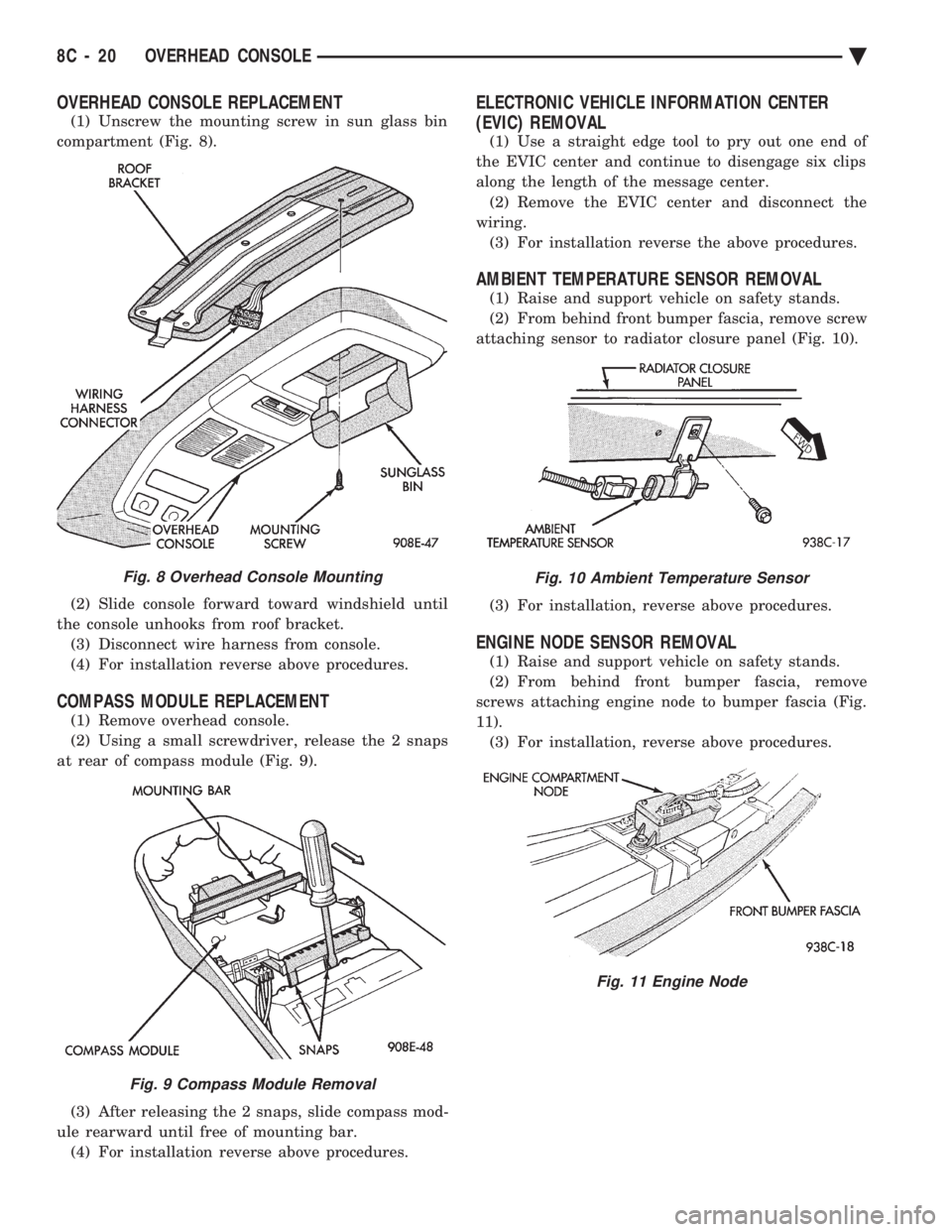
(1) Unscrew the mounting screw in sun glass bin
compartment (Fig. 8).
(2) Slide console forward toward windshield until
the console unhooks from roof bracket. (3) Disconnect wire harness from console.
(4) For installation reverse above procedures.
COMPASS MODULE REPLACEMENT
(1) Remove overhead console.
(2) Using a small screwdriver, release the 2 snaps
at rear of compass module (Fig. 9).
(3) After releasing the 2 snaps, slide compass mod-
ule rearward until free of mounting bar. (4) For installation reverse above procedures.
ELECTRONIC VEHICLE INFORMATION CENTER
(EVIC) REMOVAL
(1) Use a straight edge tool to pry out one end of
the EVIC center and continue to disengage six clips
along the length of the message center. (2) Remove the EVIC center and disconnect the
wiring. (3) For installation reverse the above procedures.
AMBIENT TEMPERATURE SENSOR REMOVAL
(1) Raise and support vehicle on safety stands.
(2) From behind front bumper fascia, remove screw
attaching sensor to radiator closure panel (Fig. 10).
(3) For installation, reverse above procedures.
ENGINE NODE SENSOR REMOVAL
(1) Raise and support vehicle on safety stands.
(2) From behind front bumper fascia, remove
screws attaching engine node to bumper fascia (Fig.
11). (3) For installation, reverse above procedures.
Fig. 8 Overhead Console Mounting
Fig. 9 Compass Module Removal
Fig. 10 Ambient Temperature Sensor
Fig. 11 Engine Node
8C - 20 OVERHEAD CONSOLE Ä
Page 437 of 2438

AP BODY INDEX
page page
Ambient Temperature Sensor Removal ........ 25
Compass Calibration ...................... 21
Compass Diagnostics ..................... 23
Compass Module Replacement .............. 25
Demagnetizing Procedure .................. 22 Map Reading Lamps Operation
.............. 21
Overhead Console Replacement ............. 25
Thermometer and Compass ................ 21
Variance Procedure ....................... 22
MAP READING LAMPS OPERATION
The map lamps are actuated by pressing on the
lens (Fig. 1).
LAMP REPLACEMENT
(1) Remove lens by inserting a screw driver or
knife blade into slot located along-side of lens. Once
screwdriver is inserted pry lens to the side and swing
down as it unhooks from housing edge. (2) Remove lamp by pulling straight down.
(3) Install new lamp by pushing firmly into recep-
tacle. (4) Snap lens into position taking care to orient
the tabs on the lens with the slots in the housing.
MAP LAMP TEST
(1) Press each lamp switch. Right hand switch
should light passenger lamp and left hand switch
should light drivers lamp. (2) If lamp does not illuminate check for a burned
out lamp, voltage, defective switch or faulty wiring.
THERMOMETER AND COMPASS
The ignition switch must be in the ON or ACCES-
SORY position before the temperature and compass
reading can be displayed. The Comp/Temp switch
turns the compass display on and off. The US/Metric
switch changes the temperature reading from Fahr-
enheit to Celsius (Fig. 2). When the vehicle is standing still, engine compart-
ment temperatures may be radiated to the tempera-
ture sensor. Therefore the most accurate ambient
temperature readings are displayed when the vehicle
is moving in a forward motion. When the ignition switch is in the ON position the
temperature display is updated every 5 minutes.
When the ignition switch is turned off the last dis-
played temperature reading stays in memory. When
the ignition switch is turned on again the thermom-
eter will display the memory temperature for 1
minute; then update the display to the actual tem-
perature within 5 minutes.
COMPASS CALIBRATION
Do not attempt to set the compass near large metal
objects, such as, other vehicles, large buildings, or
bridges. The compass unit automatically calibrates itself as
the vehicle is driven; therefore, no calibration should
be required. When the compass is first powered up,
the CAL light on the display should be on. The CAL
light will go off and the compass will be accurate af-
ter the vehicle completes one to three complete cir-
cles. If the vehicle's compass headings are inaccurate,
the compass also can be manually calibrated using
the following procedures: (1) Depress and hold down both the Comp/Temp
button and the U.S./Metric button. (2) The display will go off and after 5 seconds the
VAR light will come on. Continue to hold both but-
tons down. (3) In approximately 10 seconds, the CAL light
will come on. Release both buttons and the display
will show the heading and outside temperature. (4) Drive the vehicle 1 to 3 complete circles, with-
out turning ignition OFF. The CAL light will then
go off, showing the compass is calibrated.
Fig. 1 Overhead Console Lamp Replacement
Ä OVERHEAD CONSOLE 8C - 21
Page 454 of 2438
make sure that the spark plugs are firing. Inspect the
distributor rotor, cap, spark plug cables, and spark
plugs. If they are in proper working order, the ignition
system is not the reason why the engine will not start.
Inspect the fuel system and engine for proper opera-
tion.
FAILURE TO START TESTÐ2.5L TBI AND 3.0L
ENGINES
Before proceeding with this test make sure
Testing For Spark At Coil has been performed.
Failure to do this may lead to unnecessary diag-
nostic time and wrong test results.
WARNING: BE SURE TO APPLY PARKING BRAKE
AND/OR BLOCK WHEELS BEFORE PERFORMING
ANY TEST WITH THE ENGINE RUNNING.
(1) Battery voltage must be at least 12.4 volts to
perform test. (2) Crank the engine for 5 seconds while monitoring
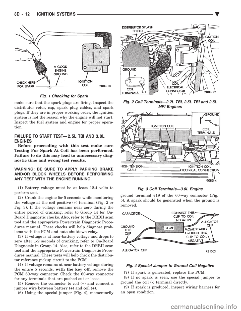
the voltage at the coil positive (+) terminal (Fig. 2 or
Fig. 3). If the voltage remains near zero during the
entire period of cranking, refer to Group 14 for On-
Board Diagnostic checks. Also, refer to the DRBII scan
tool and the appropriate Powertrain Diagnostic Proce-
dures manual. These checks will help diagnose prob-
lems with the PCM and auto shutdown relay. (3) If voltage is at near-battery voltage and drops to
zero after 1-2 seconds of cranking, refer to On-Board
Diagnostic in Group 14. Also, refer to the DRBII scan
tool and the appropriate Powertrain Diagnostic Proce-
dures manual. These tests will help check the distribu-
tor reference pickup circuit to the PCM. (4) If voltage remains at near battery voltage during
the entire 5 seconds, with the key off,remove the
PCM 60-way connector. Check the 60-way connector
for any terminals that are pushed out or loose. (5) Remove the connector to coil (+) and connect a
jumper wire between battery (+) and coil (+). (6) Using the special jumper (Fig. 4), momentarily ground terminal #19 of the 60-way connector (Fig.
5). A spark should be generated when the ground is
removed.
(7) If spark is generated, replace the PCM.
(8) If no spark is seen, use the special jumper to
ground the coil (-) terminal directly. (9) If spark is produced, inspect wiring harness for
an open condition.
Fig. 2 Coil TerminalsÐ2.2L TBI, 2.5L TBI and 2.5L MPI Engines
Fig. 3 Coil TerminalsÐ3.0L Engine
Fig. 4 Special Jumper to Ground Coil Negative
Fig. 1 Checking for Spark
8D - 12 IGNITION SYSTEMS Ä
Page 456 of 2438
2.2L TBI, 2.5L TBI, 2.5L MPI AND 3.0L IGNITION SYSTEMSÐSERVICE PROCEDURES
INDEX
page page
Coolant Temperature Sensor ................ 14
Distributor Pick-UpÐ2.2L TBI, 2.5L TBI and 2.5L MPI Engines ....................... 18
Distributor ServiceÐ3.0L Engine ............. 18
DistributorÐ2.2L TBI, 2.5L TBI and 2.5L MPI Engines .............................. 17
Idle RPM TestÐ2.5L and 3.0L Engines ........ 16
Ignition CoilÐ2.2L TBI, 2.5L TBI and 2.5L MPI Engines ....................... 14 Ignition CoilÐ3.0L Engines
................. 15
Ignition Timing ProcedureÐ2.2L TBI, 2.5L TBI, 2.5L MPI, and 3.0L Engines ............... 16
Manifold Absolute Pressure (MAP) Sensor ServiceÐ2.5L TBI and 3.0L Engines ........ 22
Powertrain Control Module (PCM) ............ 14
Spark Plug Service ....................... 15
POWERTRAIN CONTROL MODULE (PCM)
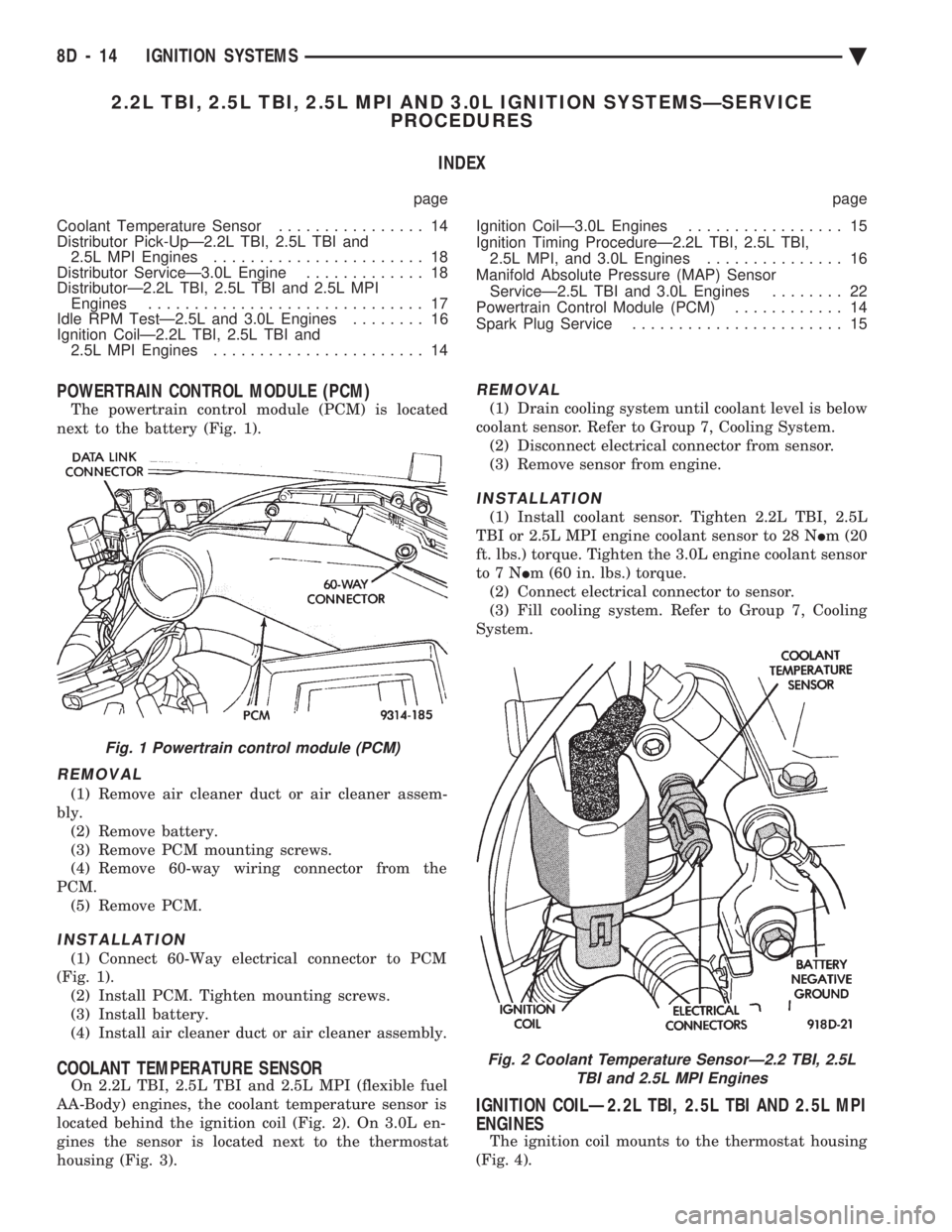
The powertrain control module (PCM) is located
next to the battery (Fig. 1).
REMOVAL
(1) Remove air cleaner duct or air cleaner assem-
bly. (2) Remove battery.
(3) Remove PCM mounting screws.
(4) Remove 60-way wiring connector from the
PCM. (5) Remove PCM.
INSTALLATION
(1) Connect 60-Way electrical connector to PCM
(Fig. 1). (2) Install PCM. Tighten mounting screws.
(3) Install battery.
(4) Install air cleaner duct or air cleaner assembly.
COOLANT TEMPERATURE SENSOR
On 2.2L TBI, 2.5L TBI and 2.5L MPI (flexible fuel
AA-Body) engines, the coolant temperature sensor is
located behind the ignition coil (Fig. 2). On 3.0L en-
gines the sensor is located next to the thermostat
housing (Fig. 3).
REMOVAL
(1) Drain cooling system until coolant level is below
coolant sensor. Refer to Group 7, Cooling System. (2) Disconnect electrical connector from sensor.
(3) Remove sensor from engine.
INSTALLATION
(1) Install coolant sensor. Tighten 2.2L TBI, 2.5L
TBI or 2.5L MPI engine coolant sensor to 28 N Im (20
ft. lbs.) torque. Tighten the 3.0L engine coolant sensor
to7N Im (60 in. lbs.) torque.
(2) Connect electrical connector to sensor.
(3) Fill cooling system. Refer to Group 7, Cooling
System.
IGNITION COILÐ2.2L TBI, 2.5L TBI AND 2.5L MPI
ENGINES
The ignition coil mounts to the thermostat housing
(Fig. 4).
Fig. 1 Powertrain control module (PCM)
Fig. 2 Coolant Temperature SensorÐ2.2 TBI, 2.5L TBI and 2.5L MPI Engines
8D - 14 IGNITION SYSTEMS Ä
Page 457 of 2438
REMOVAL
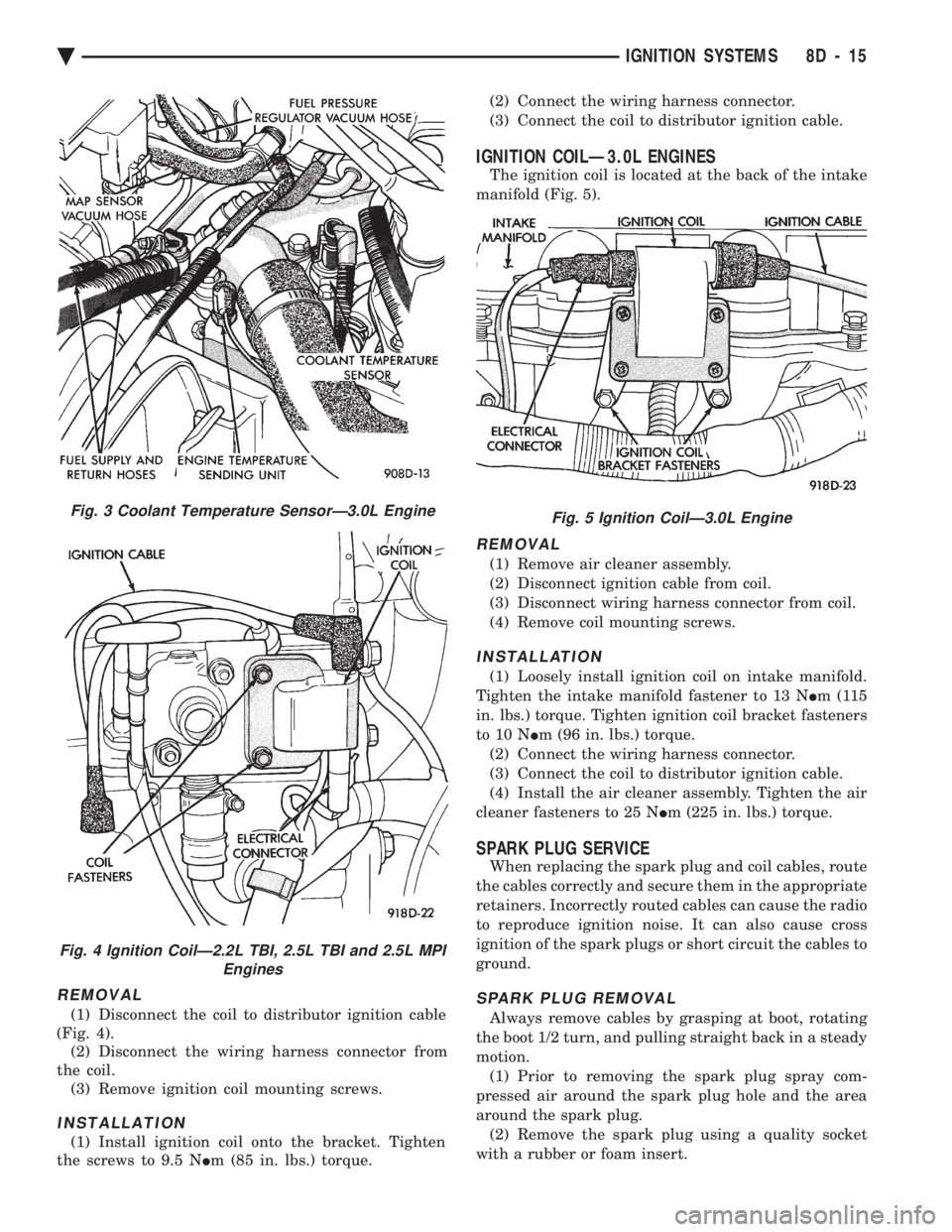
(1) Disconnect the coil to distributor ignition cable
(Fig. 4). (2) Disconnect the wiring harness connector from
the coil. (3) Remove ignition coil mounting screws.
INSTALLATION
(1) Install ignition coil onto the bracket. Tighten
the screws to 9.5 N Im (85 in. lbs.) torque. (2) Connect the wiring harness connector.
(3) Connect the coil to distributor ignition cable.
IGNITION COILÐ3.0L ENGINES
The ignition coil is located at the back of the intake
manifold (Fig. 5).
REMOVAL
(1) Remove air cleaner assembly.
(2) Disconnect ignition cable from coil.
(3) Disconnect wiring harness connector from coil.
(4) Remove coil mounting screws.
INSTALLATION
(1) Loosely install ignition coil on intake manifold.
Tighten the intake manifold fastener to 13 N Im(115
in. lbs.) torque. Tighten ignition coil bracket fasteners
to 10 N Im (96 in. lbs.) torque.
(2) Connect the wiring harness connector.
(3) Connect the coil to distributor ignition cable.
(4) Install the air cleaner assembly. Tighten the air
cleaner fasteners to 25 N Im (225 in. lbs.) torque.
SPARK PLUG SERVICE
When replacing the spark plug and coil cables, route
the cables correctly and secure them in the appropriate
retainers. Incorrectly routed cables can cause the radio
to reproduce ignition noise. It can also cause cross
ignition of the spark plugs or short circuit the cables to
ground.
SPARK PLUG REMOVAL
Always remove cables by grasping at boot, rotating
the boot 1/2 turn, and pulling straight back in a steady
motion. (1) Prior to removing the spark plug spray com-
pressed air around the spark plug hole and the area
around the spark plug. (2) Remove the spark plug using a quality socket
with a rubber or foam insert.
Fig. 3 Coolant Temperature SensorÐ3.0L Engine
Fig. 4 Ignition CoilÐ2.2L TBI, 2.5L TBI and 2.5L MPI Engines
Fig. 5 Ignition CoilÐ3.0L Engine
Ä IGNITION SYSTEMS 8D - 15
Page 459 of 2438

Fig. 10). Turn distributor housing to adjust timing.
Tighten the hold-down arm screw and recheck timing.
(8) Turn the engine off. Remove timing light or
magnetic timing unit and tachometer. If the coolant
temperature sensor was disconnected, connect the sen-
sor and erase fault codes using the Erase Fault
Code Mode on the DRBII scan tool.
DISTRIBUTORÐ2.2L TBI, 2.5L TBI AND 2.5L MPI
ENGINES
REMOVAL
(1) Disconnect distributor pick-up connector from
wiring harness connector (Fig. 11).
(2) Remove splash shield retaining screws (Fig.
12). (3) Remove splash shield (Fig. 12).
(4) Loosen distributor cap retaining screws (Fig.
13). (5) Lift cap off of distributor (Fig. 14).
(6) Rotate engine crankshaft until the distributor
rotor is pointing toward the cylinder block. Use this
as reference when reinstalling distributor. (7) Remove distributor hold-down screw.
(8) Carefully lift the distributor from the engine.
Fig. 10 Distributor HolddownÐ3.0L Engine
Fig. 11 Distributor Pickup ConnectorÐ2.5L Engine
Fig. 7 Timing ScaleÐ2.2L TBI, 2.5L TBI and 2.5L MPI Engines
Fig. 8 Timing ScaleÐ3.0L Engine
Fig. 9 Distributor HolddownÐ2.5L Engine
Ä IGNITION SYSTEMS 8D - 17
Page 460 of 2438

INSTALLATION
(1) Position distributor in engine. Make certain that
the O-ring is properly seated on distributor. If O-ring is
cracked or nicked, replace it with new one. (2) Carefully engage distributor drive with auxiliary
shaft drive. When distributor is installed properly,
rotor will be pointing toward cylinder block. If engine
has been cranked while distributor is removed,
establish proper relationship between the dis-
tributor shaft and Number 1 piston position as
follows: (a) Rotate the crankshaft until number one piston
is at top of compression stroke. Pointer on clutch
housing should be in line with the O(TDC)mark on
flywheel. (b) Rotate rotor to a position just ahead of the
number one distributor cap terminal. (c) Lower the distributor into the opening, engag-
ing distributor drive with drive on auxiliary shaft. With distributor fully seated on engine, rotor should
be under the cap number 1 tower.
(3) Install the distributor cap. Ensure all high ten-
sion wires snap firmly in the cap towers. (4) Install hold-down arm screw and finger tighten.
(5) Install splash shield.
(6) Connect distributor pick-up connector lead wire
at wiring harness connector. (7) Set ignition timing to specification. Refer to Ig-
nition Timing.
DISTRIBUTOR PICK-UPÐ2.2L TBI, 2.5L TBI AND
2.5L MPI ENGINES
REMOVAL
(1) Remove splash shield and cap. Refer to Distribu-
tor Removal. (2) Remove rotor from shaft (Fig. 15).
(3) Remove Hall effect pick-up assembly (Fig.
16).
INSTALLATION
(1) Place pick-up assembly into distributor housing
(Fig. 16). The distributor pick-up wires may be damaged
if not properly reinstalled. (2) Install rotor (Fig. 15).
(3) Install cap and splash shield. Refer to Distribu-
tor Installation.
DISTRIBUTOR SERVICEÐ3.0L ENGINE
REMOVAL
(1) Disconnect distributor connector from wiring
harness connector (Fig. 17).
Fig. 12 Splash ShieldÐ2.5L Engine
Fig. 13 Distributor Cap Retaining ScrewsÐ2.5L En- gine
Fig. 14 Distributor CapÐ2.5L Engine
8D - 18 IGNITION SYSTEMS Ä
Page 462 of 2438
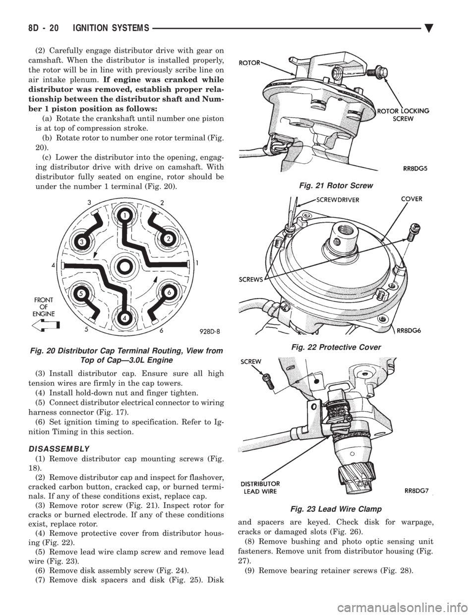
(2) Carefully engage distributor drive with gear on
camshaft. When the distributor is installed properly,
the rotor will be in line with previously scribe line on
air intake plenum. If engine was cranked while
distributor was removed, establish proper rela-
tionship between the distributor shaft and Num-
ber 1 piston position as follows: (a) Rotate the crankshaft until number one piston
is at top of compression stroke. (b) Rotate rotor to number one rotor terminal (Fig.
20). (c) Lower the distributor into the opening, engag-
ing distributor drive with drive on camshaft. With
distributor fully seated on engine, rotor should be
under the number 1 terminal (Fig. 20).
(3) Install distributor cap. Ensure sure all high
tension wires are firmly in the cap towers. (4) Install hold-down nut and finger tighten.
(5) Connect distributor electrical connector to wiring
harness connector (Fig. 17). (6) Set ignition timing to specification. Refer to Ig-
nition Timing in this section.
DISASSEMBLY
(1) Remove distributor cap mounting screws (Fig.
18). (2) Remove distributor cap and inspect for flashover,
cracked carbon button, cracked cap, or burned termi-
nals. If any of these conditions exist, replace cap. (3) Remove rotor screw (Fig. 21). Inspect rotor for
cracks or burned electrode. If any of these conditions
exist, replace rotor. (4) Remove protective cover from distributor hous-
ing (Fig. 22). (5) Remove lead wire clamp screw and remove lead
wire (Fig. 23). (6) Remove disk assembly screw (Fig. 24).
(7) Remove disk spacers and disk (Fig. 25). Disk and spacers are keyed. Check disk for warpage,
cracks or damaged slots (Fig. 26). (8) Remove bushing and photo optic sensing unit
fasteners. Remove unit from distributor housing (Fig.
27). (9) Remove bearing retainer screws (Fig. 28).
Fig. 21 Rotor Screw
Fig. 22 Protective Cover
Fig. 23 Lead Wire Clamp
Fig. 20 Distributor Cap Terminal Routing, View from Top of CapÐ3.0L Engine
8D - 20 IGNITION SYSTEMS Ä