1993 CHEVROLET PLYMOUTH ACCLAIM wiring
[x] Cancel search: wiringPage 376 of 2438

It is important when using the Test Indicator that
the battery be level and have a clean top to see the
correct indications. A light may be required to view
the Indicator.
WARNING: DO NOT USE OPEN FLAME NEAR BAT-
TERY BECAUSE OF EXPLOSIVE GASES AT FORM
ABOVE BATTERY.
STATE OF CHARGE TESTS
USING TEST INDICATOR
The built in test hydrometer (Figs. 3, 4 and 5) mea-
sures the specific gravity of the electrolyte. Specific
Gravity (SG) of the electrolyte will show state of
charge voltage. The test indicator WILL NOT show
cranking capacity of the battery. Refer to Battery
Load. Look into the sight glass (Figs. 4 and 5) and
note the color of the indicator (Fig. 5). Refer to the
following description of colors:
² GREEN = 75 to 100 degree state of charge
The battery is adequately charged for further test-
ing and may be returned to use. If the vehicle will
not crank for a maximum 15 seconds, refer to Bat-
tery Load Test in this Group for more information.
² BLACK OR DAR K=0to75degree state of
charge The battery is INADEQUATELY charged and
must be charged until green dot is visible, (12.4 volts
or greater) before the battery is tested or returned to
use. Refer to Causes of Battery Discharging.
² YELLOW OR BRIGHT COLOR = Battery must
be replace
WARNING: DO NOT CHARGE, ASSIST BOOST,
LOAD TEST, OR ADD WATER TO THE BATTERY
WHEN YELLOW OR BRIGHT COLOR DOT IS VISI-
BLE. PERSONAL INJURY MAY OCCUR.
A yellow or bright color dot shows electrolyte level
in battery is below the test indicator (Fig. 5). Water
cannot be added to a maintenance free battery. The
battery must be replaced. A low electrolyte level may
be caused by an over charging condition. Refer to
Generator Test Procedures on Vehicle.
CAUSES OF BATTERY DISCHARGING
It is normal to have a small 5 to 30 milliamperes
continuous electrical draw from the battery. This
draw will take place with the ignition in the OFF po-
sition, and the courtesy, dome, storage compart-
ments, and engine compartment lights OFF. The
continuous draw is due to various electronic features
or accessories that require electrical current with the
ignition OFF to function properly. When a vehicle is
not used over an extended period approximately 20
days the Main Fusible Link Connector (Fig. 6)
should be disconnected. This is located near the bat- tery on the engine wiring harness. Disconnection of
this connector will help prevent battery discharging.
Refer to Fig. 7 for Battery Diagnostics.
ABNORMAL BATTERY DISCHARGING
(1) Corroded battery posts, cables or terminals.
(2) Loose or worn generator drive belt.
(3) Electrical loads that exceed the output of the
charging system due to equipment or accessories in-
stalled after delivery. (4) Slow driving speeds in heavy traffic conditions
or prolonged idling with high-amperage electrical
systems in use. (5) Defective electrical circuit or component caus-
ing excess Ignition Off Draw (IOD). Refer to Ignition
OFF Draw (IOD). (6) Defective charging system.
(7) Defective battery.
BATTERY OPEN CIRCUIT VOLTAGE TEST
An open circuit voltage, no load test will show the
state of charge in a battery. Also, if it will pass a
load test of 50 percent of the battery cold crank rat-
ing. Refer to Battery Load Test. If a battery has an
open circuit voltage reading of 12.4 volts or greater,
and will not pass a load test, it is defective and re-
placement would be required. To test open circuit
voltage, perform the following operation: (1) Remove both battery cables, negative first. If
the battery has been boosted, charged, or loaded just
prior to this operation, allow the battery a few min-
utes to stabilize. (2) Using a voltmeter connected to the battery
posts and measure the open circuit voltage (Fig. 8).
Fig. 6 Main Fusible Link Connector
8A - 4 BATTERY/STARTING/CHARGING SYSTEMS DIAGNOSTICS Ä
Page 381 of 2438

IGNITION OFF DRAW (IOD)
GENERAL INFORMATION
A normal electrical system will draw from 5 to 30
milliamperes from the battery. This is with the ignition
in the OFF position, and all non-ignition controlled cir-
cuits in proper working order. The amount of IOD will
depend on body model and electrical components. A ve-
hicle that has not been operated for an extended period
of approximately 20 days may discharge the battery to
an inadequate level. In this case, the Main Fusible Link
Connector should be disconnected. The Main Fusible
Link connector is located rearward of the battery on the
engine wiring harness (Fig. 19).
If the IOD is over 30 milliamperes, the defect must
be found and corrected before condemning the bat-
tery. Usually, the battery can be charged and re-
turned to service (Fig. 16).
IGNITION OFF DRAW (IOD) TESTS
VEHICLES WITHOUT ELECTRONIC AUTOMATIC TRANSMISSION/LOAD LEVELINGSUSPENSION OR ALARM SYSTEMS
Testing for HIGHER AMPERAGE IOD must be
performed first to prevent damage to most milliamp
meters. A standard 12 volt test light and a milliamp meter
that is equipped with two leads will be used for the
following tests. The milliamp meter should be able to
handle up to two amps.
(1) Verify that all electrical accessories are OFF.
Turn off all lights, close trunk lid, close glove box door,
turn off sun visor vanity lights, close all doors and re- move ignition key. Allow the Illuminated Entry System
if equipped to time out in approximately 30 seconds.
(2) Verify the engine compartment lamp bulb is
working by opening/closing hood. Remove the lamp. (3) Disconnect negative battery cable (Fig. 15).
(4) Connect a typical 12 volt test light between the
negative cable clamp and the negative battery post (Fig.
19). The test light may be brightly lit for up to three
minutes or may not be lit at all. This depending on the
body model or electronic components on the vehicle. (a) The term brightly used throughout the follow-
ing tests. This implies the brightness of the test light
will be the same as if it were connected across the
battery posts. This would be with a fully charged bat-
tery.
(b) The test light or the milliamp meter MUST
be positively connected to the battery post and the
battery cable during all IOD testing. (c) Do not allow the test light or the milliamp
meter to become disconnected during any of the
IOD tests. If this happens, the electronic timer
functions will be started and all IOD tests must be
repeated from the beginning. Clamp the test light
at both ends to prevent accidental disconnection.
(d) After three minutes time has elapsed, the test
light should turn OFF or be dimly lit depending on
the electronic components on the vehicle. If the test
light remains BRIGHTLY lit, do not disconnect test
light. Disconnect each fuse or circuit breaker until
test light is either OFF or DIMLY lit. Refer to the
Front Wheel Drive Car Wiring Diagrams Service
Manual. This will eliminate higher amperage IOD. It
is now safe to install the milliamp meter without
damage to the meter to check for low amperage IOD.
(e) Possible sources of high IOD are usually ve-
hicle lamps trunk lamp, glove compartment, lug-
gage compartment, etc.. (f) If test light is still brightly lit after discon-
necting each fuse and circuit breaker, disconnect
the wiring harness from the generator. Refer to
Generator Testing. Do not disconnect test light.
CAUTION: This last test has higher amperage IOD and
must be performed before going on with low amper-
age IOD tests. The higher amperage IOD must be elim-
inated before hooking up milliamp meter to check for
low amperage IOD. If higher amperage IOD has not
been eliminated, milliamp meter may be damaged.
Most milliamp meters will not handle over one or two
amps. Do not hook up meter if test light is glowing
brightly. Refer to maximum amperage specifications
and instructions supplied with milliamp meter.
After higher amperage IOD has been corrected, low
amperage IOD may be checked. The MAXIMUM IOD=
30 MILLIAMPERES.
Fig. 19 IOD Test
Ä BATTERY/STARTING/CHARGING SYSTEMS DIAGNOSTICS 8A - 9
Page 382 of 2438

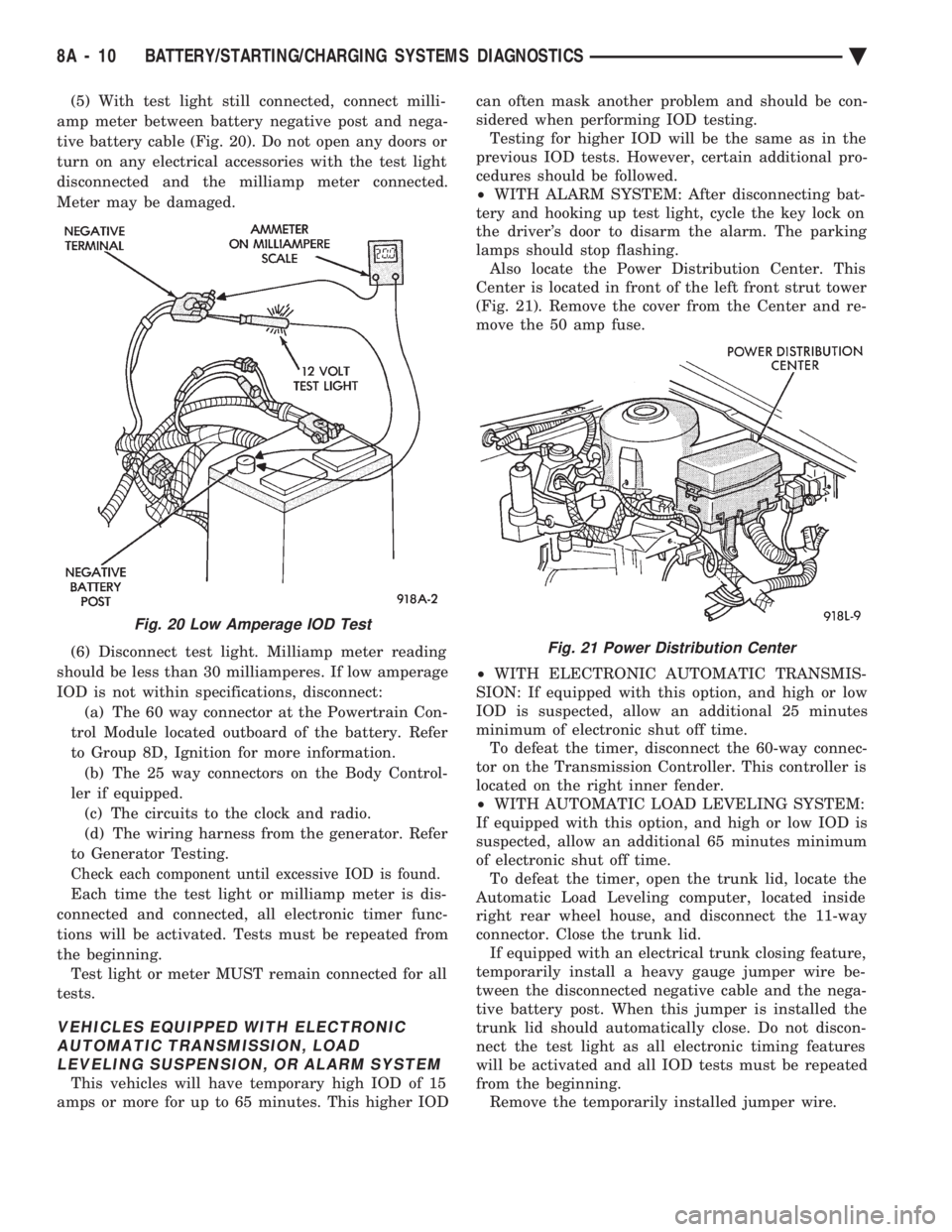
(5) With test light still connected, connect milli-
amp meter between battery negative post and nega-
tive battery cable (Fig. 20). Do not open any doors or
turn on any electrical accessories with the test light
disconnected and the milliamp meter connected.
Meter may be damaged.
(6) Disconnect test light. Milliamp meter reading
should be less than 30 milliamperes. If low amperage
IOD is not within specifications, disconnect: (a) The 60 way connector at the Powertrain Con-
trol Module located outboard of the battery. Refer
to Group 8D, Ignition for more information. (b) The 25 way connectors on the Body Control-
ler if equipped. (c) The circuits to the clock and radio.
(d) The wiring harness from the generator. Refer
to Generator Testing.
Check each component until excessive IOD is found.
Each time the test light or milliamp meter is dis-
connected and connected, all electronic timer func-
tions will be activated. Tests must be repeated from
the beginning. Test light or meter MUST remain connected for all
tests.
VEHICLES EQUIPPED WITH ELECTRONIC AUTOMATIC TRANSMISSION, LOADLEVELING SUSPENSION, OR ALARM SYSTEM
This vehicles will have temporary high IOD of 15
amps or more for up to 65 minutes. This higher IOD can often mask another problem and should be con-
sidered when performing IOD testing. Testing for higher IOD will be the same as in the
previous IOD tests. However, certain additional pro-
cedures should be followed.
² WITH ALARM SYSTEM: After disconnecting bat-
tery and hooking up test light, cycle the key lock on
the driver's door to disarm the alarm. The parking
lamps should stop flashing. Also locate the Power Distribution Center. This
Center is located in front of the left front strut tower
(Fig. 21). Remove the cover from the Center and re-
move the 50 amp fuse.
² WITH ELECTRONIC AUTOMATIC TRANSMIS-
SION: If equipped with this option, and high or low
IOD is suspected, allow an additional 25 minutes
minimum of electronic shut off time. To defeat the timer, disconnect the 60-way connec-
tor on the Transmission Controller. This controller is
located on the right inner fender.
² WITH AUTOMATIC LOAD LEVELING SYSTEM:
If equipped with this option, and high or low IOD is
suspected, allow an additional 65 minutes minimum
of electronic shut off time. To defeat the timer, open the trunk lid, locate the
Automatic Load Leveling computer, located inside
right rear wheel house, and disconnect the 11-way
connector. Close the trunk lid. If equipped with an electrical trunk closing feature,
temporarily install a heavy gauge jumper wire be-
tween the disconnected negative cable and the nega-
tive battery post. When this jumper is installed the
trunk lid should automatically close. Do not discon-
nect the test light as all electronic timing features
will be activated and all IOD tests must be repeated
from the beginning. Remove the temporarily installed jumper wire.
Fig. 20 Low Amperage IOD Test
Fig. 21 Power Distribution Center
8A - 10 BATTERY/STARTING/CHARGING SYSTEMS DIAGNOSTICS Ä
Page 383 of 2438

STARTER TEST PROCEDURES ON VEHICLE INDEX
page page
Diagnostic Preparation ..................... 11
General Information ....................... 11 Starter Control Circuit Tests
................ 15
Starter Feed Circuit Tests .................. 11
GENERAL INFORMATION
The starting system (Fig. 1) has:
² Ignition switch
² Starter relay (Fig. 2)
² Neutral starting and back-up switch with auto-
matic transmissions
² Clutch pedal mounted starter interlock switch
with manual transmissions
² Wiring harness
² Battery
² Starter motor with an integral solenoid
These components form two separate circuits. A
high amperage circuit that feeds the starter motor up
to 300+ amps, and a control circuit that operates on
less than 20 amps.
DIAGNOSTIC PREPARATION
Before going on with starting system diagnostics,
verify: (1) The battery top, posts, and terminals are clean.
(2) The generator drive belt tension and condition
is correct. (3) The battery state-of-charge is correct.
(4) The battery will pass load test.
(5) The battery cable connections at the starter
and engine block are clean and free from corrosion. (6) The wiring harness connectors and terminals
are clean and free from corrosion. (7) Proper circuit grounding.
(8) Refer to Starter System Diagnostics (Fig. 3).
STARTER FEED CIRCUIT TESTS
The following procedure will require a suitable
volt/ampere tester (Fig. 4).
CAUTION: Ignition system also must be disabled to
prevent engine start while performing the following
tests.
(1) Connect a volt-ampere tester (Fig. 4) to the bat-
tery terminals (Fig. 5). Refer to the operating in-
structions provided with the tester being used. (2) Disable ignition system as follows:
² VEHICLES WITH CONVENTIONAL DISTRIBU-
TORS: Disconnect the ignition coil cable from the
distributor cap. Connect a suitable jumper wire be-
tween the coil cable end-terminal and a good body
ground (Fig. 6).
Fig. 1 Starting Components/Wiring
Fig. 2 Starter Relay
Ä BATTERY/STARTING/CHARGING SYSTEMS DIAGNOSTICS 8A - 11
Page 386 of 2438

STARTER FEED CIRCUIT RESISTANCE TEST
Before going on with this operation, review Diag-
nostic Preparation and Starter Feed Circuit Tests.
The following operation will require a voltmeter, ac-
curate to 1/10 of a volt.
CAUTION: Ignition system also must be disabled to
prevent engine start while performing the following
tests.
(1) Disable ignition system as follows:
² VEHICLES WITH CONVENTIONAL DISTRIBU-
TORS: Disconnect the ignition coil cable from the
distributor cap. Connect a suitable jumper wire be-
tween the coil cable end-terminal and a good body
ground (Fig. 6).
² VEHICLES WITH DIRECT IGNITION SYSTEM:
Disconnect the ignition coils electrical connector (Fig.
7). (2) With all wiring harnesses and components
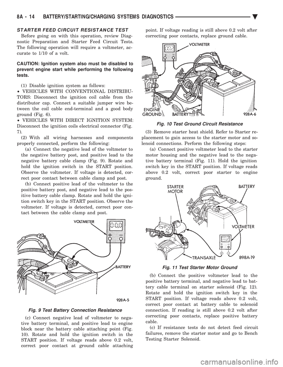
properly connected, perform the following: (a) Connect the negative lead of the voltmeter to
the negative battery post, and positive lead to the
negative battery cable clamp (Fig. 9). Rotate and
hold the ignition switch in the START position.
Observe the voltmeter. If voltage is detected, cor-
rect poor contact between cable clamp and post. (b) Connect positive lead of the voltmeter to the
positive battery post, and negative lead to the pos-
itive battery cable clamp. Rotate and hold the igni-
tion switch key in the START position. Observe the
voltmeter. If voltage is detected, correct poor con-
tact between the cable clamp and post.
(c) Connect negative lead of voltmeter to nega-
tive battery terminal, and positive lead to engine
block near the battery cable attaching point (Fig.
10). Rotate and hold the ignition switch in the
START position. If voltage reads above 0.2 volt,
correct poor contact at ground cable attaching point. If voltage reading is still above 0.2 volt after
correcting poor contacts, replace ground cable.
(3) Remove starter heat shield. Refer to Starter re-
placement to gain access to the starter motor and so-
lenoid connections. Perform the following steps: (a) Connect positive voltmeter lead to the starter
motor housing and the negative lead to the nega-
tive battery terminal (Fig. 11). Hold the ignition
switch key in the START position. If voltage reads
above 0.2 volt, correct poor starter to engine
ground.
(b) Connect the positive voltmeter lead to the
positive battery terminal, and negative lead to bat-
tery cable terminal on starter solenoid (Fig. 12).
Rotate and hold the ignition switch key in the
START position. If voltage reads above 0.2 volt,
correct poor contact at battery cable to solenoid
connection. If reading is still above 0.2 volt after
correcting poor contacts, replace positive battery
cable. (c) If resistance tests do not detect feed circuit
failures, remove the starter motor and go to Bench
Testing Starter Solenoid.
Fig. 9 Test Battery Connection Resistance
Fig. 10 Test Ground Circuit Resistance
Fig. 11 Test Starter Motor Ground
8A - 14 BATTERY/STARTING/CHARGING SYSTEMS DIAGNOSTICS Ä
Page 387 of 2438

STARTER CONTROL CIRCUIT TESTS
The starter control circuit has:
² Starter solenoid
² Starter relay (Fig. 2)
² Neutral starting and back-up switch with auto-
matic transmissions
² Clutch pedal mounted starter interlock switch
with manual transmissions
² Ignition switch
² Battery
² All related wiring and connections
CAUTION: Before performing any starter tests, the
ignition system must be disabled.
² VEHICLES EQUIPPED WITH A CONVEN-
TIONAL DISTRIBUTOR: Disconnect coil wire from
distributor cap center tower. Secure wire to a good
ground to prevent engine from starting (Fig. 6).
² VEHICLES EQUIPPED WITH DIRECT IGNI-
TION SYSTEM: Unplug the coils electrical connector
(Fig. 7).
STARTER SOLENOID TEST
WARNING: CHECK TO ENSURE THAT THE TRANS-
MISSION IS IN PARK OR NEUTRAL WITH THE
PARKING BRAKE APPLIED
(1) Verify battery condition. Battery must be in
good condition with a full charge before performing
any starter tests. Refer to Battery Tests. (2) Perform this starter solenoid test BEFORE per-
forming the starter relay test. (3) Raise the vehicle.
(4) Perform a visual inspection of the starter/
starter solenoid for corrosion, loose connections or
faulty wiring. (5) Lower the vehicle.
(6) Locate the starter relay as follows:
² On AC, AG, AJ and AY Bodies the relay is located
in the Power Distribution Center. This Center is mounted near the front of the left front strut tower
(Fig. 13). The position of the starter relay within this
Center will be shown on the Center cover.
² On AA/AP Bodies the relay is located on the front
of the left front strut tower (Fig. 14).
(7) Remove the starter relay from the connector.
(8) Connect a remote starter switch or a jumper
wire between the battery positive post and terminal
87 on the starter relay connector. To decide the
starter relay terminal numbers, refer to the Starter
Relay Tests.
² If engine now cranks, starter/starter solenoid is
good. Go to the starter relay test.
² If engine does not crank with this test, or solenoid
chatters, check wiring and connectors from starter
Fig. 12 Test Positive Battery Cable Resistance
Fig. 13 Starter Relay LocationÐAC, AG, AJ, and AY Bodies
Fig. 14 Starter Relay LocationÐAA/AP Body
Ä BATTERY/STARTING/CHARGING SYSTEMS DIAGNOSTICS 8A - 15
Page 388 of 2438

relay to starter solenoid for loose or corroded connec-
tions. Particularly at starter terminals.
² Repeat test. If engine still fails to crank properly,
trouble is within starter or starter mounted solenoid,
and it must be removed for repairs. Refer to Group
8B, Battery/Starter/Generator Service, Starter re-
placement.
STARTER RELAY TEST
WARNING: CHECK TO ENSURE THAT THE TRANS-
MISSION IS IN PARK OR NEUTRAL WITH THE
PARKING BRAKE APPLIED
(1) Verify battery condition. Battery must be in
good condition with a full charge before performing
any starter tests. Refer to Battery Tests. (2) Perform the preceding starter solenoid tests
BEFORE performing starter relay tests. Refer to
Starter Solenoid Test. (3) Locate and remove the starter relay. For
starter relay locations, refer to Starter Solenoid Test
(Fig. 13 or 14). (4) After the starter relay has been located and re-
moved, refer to Starter Relay Tests (Fig. 15).
NEUTRAL STARTING AND BACK-UP SWITCH
AUTOMATIC TRANSMISSION ONLY
For electrical diagnostics, when checking starter
circuits, refer to Starter Relay Tests (Fig. 15). For replacement of switch, refer to Group 21, Tran-
saxle, Neutral Starting and Switch Replacement.
STARTER INTERLOCK SWITCHÐCLUTCH PEDAL MOUNTED
MANUAL TRANSMISSION ONLY
For electrical diagnostics, refer to the Starter Relay
Tests. For replacement and/or adjustment of the switch,
refer to Group 6, Manual Transaxle Clutch, Manual
Transaxle Starter Interlock Switch.
IGNITION SWITCH TEST
After testing the starter solenoid and relay, test ig-
nition switch and wiring. Refer to Group 8D, Ignition
Systems, or the Front Wheel Drive Car Wiring Dia-
grams Service Manual. Check all wiring for opens or
shorts, and all connectors for being loose or corroded.
BENCH TESTING STARTER SOLENOID
(1) Disconnect field coil wire from field coil termi-
nal (Fig. 16 or 17). (2) Check for continuity between solenoid terminal
and field coil terminal with a continuity tester. Con-
tinuity should be detected (Fig. 18 or 19). (3) Check for continuity between solenoid terminal
and solenoid housing (Fig. 20 or 21). Continuity
should be detected. If continuity is detected, solenoid
is good. (4) If continuity is not detected in either test, sole-
noid has an open circuit and is defective. If equipped
with:
² BOSCH STARTER: Replace the solenoid.
² NIPPONDENSO STARTER: Replace the starter
assembly.
8A - 16 BATTERY/STARTING/CHARGING SYSTEMS DIAGNOSTICS Ä
Page 393 of 2438

(5) Connect an engine tachometer and connect bat-
tery negative cable. (6) Connect a volt/amp tester equipped with a vari-
able carbon pile rheostat between battery terminals
(Fig. 6). Be sure carbon pile is in OFF position before
connecting leads. (7) Remove fresh air hose between Powertrain
Control Module computer and air cleaner if neces-
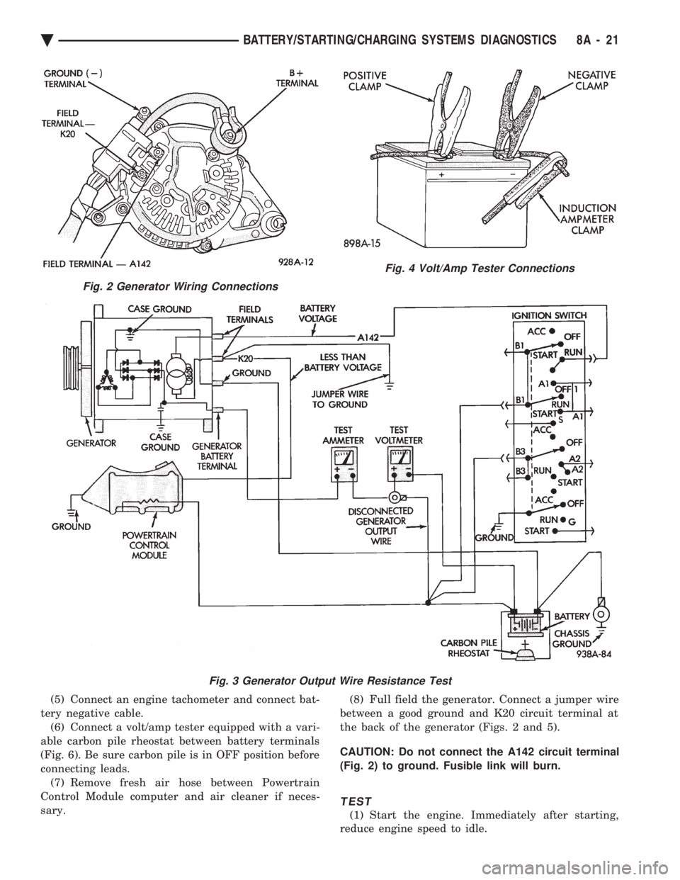
sary. (8) Full field the generator. Connect a jumper wire
between a good ground and K20 circuit terminal at
the back of the generator (Figs. 2 and 5).
CAUTION: Do not connect the A142 circuit terminal
(Fig. 2) to ground. Fusible link will burn.
TEST
(1) Start the engine. Immediately after starting,
reduce engine speed to idle.
Fig. 2 Generator Wiring Connections
Fig. 3 Generator Output Wire Resistance Test
Fig. 4 Volt/Amp Tester Connections
Ä BATTERY/STARTING/CHARGING SYSTEMS DIAGNOSTICS 8A - 21